

Page 1

We manage heat
®
®
Model GPT–3
Freeze Protection Thermostat
Part Number 19425
Installation and Operation Manual
Environmental Technology, Inc.
1850 N Sheridan Street
South Bend, Indiana 46628
(574) 233-1202 or (800) 234-4239
FAX (574) 233-2152 or (888) 234-4238
http://www.networketi.com/
Page 2

DISCLAIMER
Environmental Technology, Inc. makes no representations or warranties, either expressed or implied,
with respect to the contents of this publication or the products that it describes, and specifically
disclaims any implied warranties of merchantability or fitness for any particular purpose.
Environmental Technology, Inc. reserves the right to revise this publication and to make changes and
improvements to the products described in this publication without the obligation of Environmental
Technology, Inc. to notify any person or organization of such revisions, changes or improvements.
Copyright © 2005 Environmental Technology, Inc. All rights reserved. No part of this manual may be
reproduced or translated in any form or by any means, electronic or mechanical including photocopying
and recording, for any purpose without the express written consent of Environmental Technology, Inc.
The ETI logo, We Manage Heat, Tracon and GPT are reg is tered trademarks of En vi ron men tal
Technology, Inc.
Printed in USA
PN20656 rev 6/2006
Page 3

Table of Contents
Safety 7
Contacting Environmental Technology 7
General 7
Introduction 7
Specifi cations 9
Operation 10
Normal 10
Abnormal 10
Installation 10
First 10
Next 10
Location 11
Supply and Heater Connections 11
Sensor and Alarm Relay Connections 12
General 12
Temperature Sensors 12
Alarm Relay Contacts 14
Setup 14
Factory Settings 14
Custom Settings 15
General 15
GFEP 15
Mode 15
Current 16
Constant Wattage Heater Mode 16
Maintenance 17
General 17
Troubleshooting 17
Returns 17
Page 3 of 21
Page 4

Page 4 of 21
Page 5

Index of Figures
Figure 1. GPT–3 dimensional drawing 8
Figure 2. GPT–3 wiring diagram 11
Figure 3. Control and monitor sensor connections for self-limiting heaters 12
Figure 4. Control sensor connection for constant wattage heaters 13
Figure 5. Alarm relay connections 13
Figure 6. DIP switch detail 14
Figure 7. Removing electronic assembly from housing 15
Appendix A. GPT–3 dimensional drawing. 18
Appendix B. GPT–3 wiring diagram. 19
Appendix C. Control and monitor sensor connections for self-limiting heaters. 20
Appendix D. Control and monitor sensor connections for constant wattage heaters 21
Page 5 of 21
Page 6

Page 6 of 21
Page 7

Safety
Make all electrical connections in compliance with the National Electric Code (NFPA 70)
and local electrical code. If you have questions concerning the installation or application, contact
Customer Service.
Contacting Environmental Technology
For assistance, contact Customer Service. Office hours are 8:00 AM until 5:00 PM EST
(UTC minus five hours).
Voice: (800) 234.4239 (USA and Canada) or (574) 233.1202 (elsewhere)
Fax: (888) 234.4238 (USA and Canada) or (574) 233.2152 (elsewhere)
E-mail: helpdesk@networketi.com
Mail: Environmental Technology, Inc.
1850 North Sheridan Street
South Bend, IN 46628
General
Introduction
The GPT–3 Freeze Protection Thermostat has a calibrated adjustment range of 41° to 77°F
(5° to 25°C) with a control band of 2°F (1°C). Heaters operate at ambient temperatures below the
set temperature.
The GPT–3 combines temperature control using either constant wattage or self-limiting
heaters with GFEP (ground fault equipment protection) and advanced monitoring features. For
example, although the GFEP is factory set to trip at 30 mA, this threshhold can be set to 60,
90 or 120 mA to cure nuisance tripping problems. Keeping wet fire sprinklers from freezing is
considered to be a higher priority than interrupting heater power in the event of a ground fault
condition. The GPT–3 accommodates this requirement by allowing the GFEP to be set only to
alarm while the ground fault persists.
Other features include continuous heater monitoring with separate modes for constant
wattage and self-limiting heaters. A trickle current verifies heater continuity of both heater
types when there is no call for heat. The current flow through constant wattage heaters verifies
continuity during operation. Self-limiting heaters employ an independent temperature monitor
sensor (included) to measure the hot-end temperature. Depending upon how long it takes the
cable to reach its operating temperature such that the monitor sensor is less than 5°F (3°C) below
Page 7 of 21
Page 8
the control sensor temperature, the GPT–3 may momentarily declare a cold heater.
The GPT–3 automatically executes a self-test every 24 hours. First, heaters are de-
energized. Then, the GFEP verifies its own operation. Finally, it checks the heaters for ground
fault under operating conditions. This entire process takes about two seconds.
Other features include verifying the integrity of both the control and monitor temperature
sensors and checking the contactor for open or shorted contacts. A control temperature sensor
failure also inhibits contactor operation in addition to asserting an alarm condition.
The GPT–3 automatically accommodates 120, 208, 240 and 277 supply voltages. Since
the heaters and the GPT–3 operate from the same supply voltage, the safety hazard created by
multiple points of disconnect is eliminated. The heater control contactor is rated for up to 30
amps.
The GPT–3 provides a reverse acting isolated Class 2 alarm relay contact SPDT rated at one
amp. Reverse action makes absence of supply voltage an alarmed condition.
Although the GPT–3 housing is NEMA 3R rated for indoor or outdoor service, a protected
location is recommended. The operating temperature range is −40° to 136° F (−40° to 58°C).
Padlocking the transparent front cover can prevent tampering without interfering with the view
of the status indicators.
3
/4" (21mm)
Conduit Entry
Grounding Lug
3
/4" (21mm)
Conduit Entry
Low Voltage
Compartment
High Voltage
Compartment
(102mm)
C
L
2"
(51mm)
4"
1
/8"
2
(54mm)
J1
C
L
1
/2"
11
(292mm)
12"
(305mm)
TRACON
GFEP
FAULT
HEATER
FAULT
GFEP
®
–
GPT
RESET
50
10
TEST
5
41
Temperature
®
http://www.networketi.com
e-mail: helpdesk@networketi.com
3
®
SUPPLY
HEATER
59
15
25
°C
°F
We Manage Heat
68
20
77
®
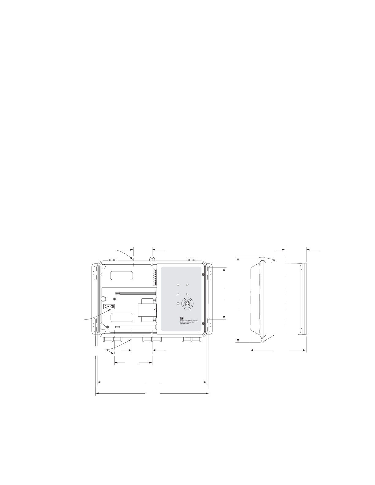
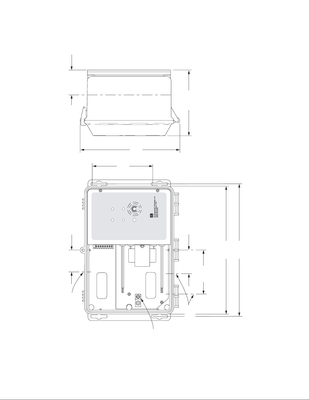
Figure 1. GPT–3 dimensional drawing
51/2"
(140mm)
1
/8"
9
(232mm)
9
/16"
6
(167mm)
C
L
25/16"
(59mm)
Page 8 of 21
Page 9

Specifi cations
Control
Range: 41° to 77°F (5° to 25°C)
Dead band: 2°F (1°C)
Electrical
Supply: 120, 208, 240 or 277 volts auto-selected
Heater load: 30 amps maximum
Alarm relay: Isolated SPDT 1 amp Class 2 contact
Indicators
Supply (red) Power applied
Heater (yellow) Call for heat
GFEP (red) Ground fault occurring or has occurred
FAULT (red) Contactor failure
Temperature sensor failure
Power-on self-check failure
GFEP
Settings: 30 mA default, 60, 90, 120 mA selectable
Reset: Manual default, automatic selectable
Auto-test: Every 24 hours
Heater monitoring
Choices: Self-limiting default, constant wattage selectable
Alarm relay: No power
Heater failure
Contactor failure
Ground fault or GFEP circuit failure
Temperature sensor failure
Temperature limits
Operating: −40° to 136° F (−40° to 58° C)
Storage: −67° to 167° F (−55° to 75° C)
Page 9 of 21
Page 10

Operation
Normal
The GPT–3 requires little or no attention after installation. Although changing the
temperature setting can improve heating system performance, this is seldom necessary. Minimum
energy use occurs when the the temperature is set to the minimum value providing the desired
heating performance.
Normal operation occurs when neither the Fault nor the GFEP indicators operate and the
Alarm relay is off. Otherwise, operation is abnormal.
Abnormal
With one exception, operation of either the Alarm relay or Fault indicator or both means that
a failure has occurred that requires a qualified electrician to correct. The exception is momentary
indication of a self-limiting heater failure as is shown by blinking the Heater indicator when
the GPT–3 is used with self-limiting cable. The GPT–3 detects a self-limiting heater failure by
measuring its temperature at the far end of the cable. Depending upon how long it takes the cable
to reach its operating temperature such that the monitor sensor is less than 5°F (3°C) below the
control sensor temperature, the GPT–3 may momentarily declare a cold heater.
Many indicators display additional information concerning equipment failures through
flashing. Check the Troubleshooting section for additional information since service by qualified
personnel is required.
Installation
First
Inspect the package and its contents for damage. In the event of damage, immediately
contact Environmental Technology, Inc. Customer Service.
Next
Check the contents of the package against the pro forma Packing List shown below. If
discrepancies are found, contact ETI Customer Service before starting the installation.
Pro Forma Packing List
Order Number Quantity Description
19425 1 GPT–3 Freeze Protection Thermostat
19272 2 Temperature Sensor
20656 1 GPT–3 Installation and Operation Manual
18703 4 Wire Nuts, Red
Page 10 of 21
Page 11
Location
The GPT–3 is suitable for indoor or outdoor mounting on a vertical surface. Although the
NEMA 3R rated housing is strong and durable, choose a protected location for an extra safety
margin. Always consider the possibilities of tampering and vandalism when choosing a location.
Keep the GPT–3 and the heat cable as close together as is practical to minimize installation
costs. There is a 2,000’ (610m) limit on temperature sensor extension wiring.
Figure 1 shows mechanical dimensions of the GPT–3. Note the location of the
compartment provided for low voltage Class 2 connections.
Supply and Heater Connections
The GPT–3 operates from 120, 208, 240 or 277 volts which it automatically selects. The
heaters and GPT–3 operate from the same supply voltage.
The definite purpose DPST heater control contactor is rated for up to 30 AMP loads at 277
volts or less.
Make the supply voltage and heater connections in the compartment provided for this
purpose. See Figure 1.
Use only copper wire for supply, heater and safety ground connections. Select a minimum
Equipment
Safety
Ground
Heater Shield
Ground
J1
From 120, 208,
240, or 277 VAC
Supply
GPT
TRACON
GFEP
FAULT
HEATER
FAULT
RESET
GFEP
TEST
®
–
3
®
59
15
50
10
5
41
°C
°F
Temperature
®
We Manage Heat
http://www.networketi.com
e-mail: helpdesk@networketi.com
SUPPLY
HEATER
25
68
20
77
®
To Heater
30 Amp Load Max
.
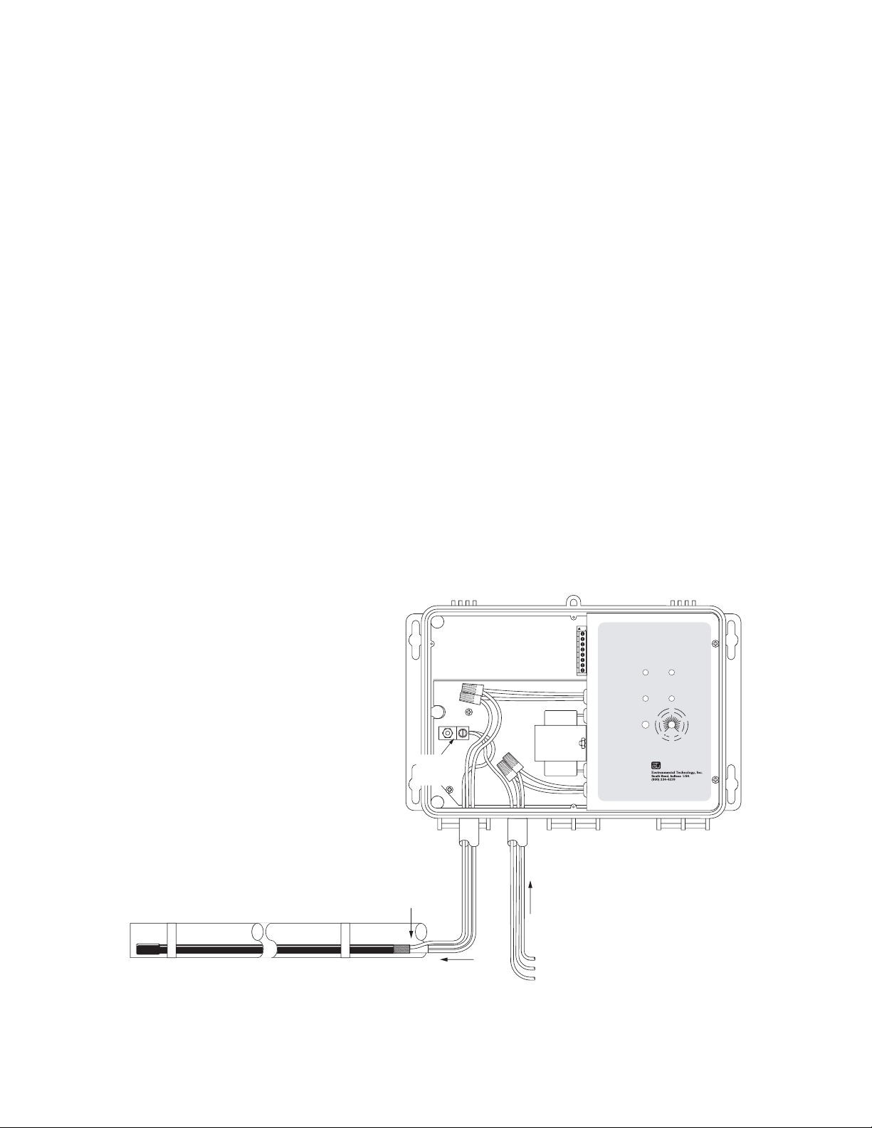
Figure 2. GPT–3 wiring diagram
Line/L1
Neutral/L2
Ground
Page 11 of 21
Page 12

wire size of 10 AWG with, minimum, 300 volt insulation rated for at least 75ºC.
Figure 2 shows a pictorial wiring diagram of the heater and supply voltage connections. Use
appropriately rated wire nuts or bomb splices for all heater and supply connections. Connect the
equipment safety ground and heater shield ground to the lug provided for this purpose.
Sensor and Alarm Relay Connections
General
The two temperature sensors are connected to the terminal block in the low voltage
compartment along with the connections to the reverse acting isolated SPDT alarm relay. Use
#18 AWG copper wire with insulation rated for 300 volt service for all Class 2 connections
unless otherwise noted. Using jacketed extension wiring, although convenient, is not necessary.
Using metallic conduit for extension wires is recommended. Never route Class 2 circuits in
the conduit used for supply and heater voltage circuits.
Temperature Sensors
Two identical temperature sensors are supplied with the GPT–3. Each is supplied with
20' (6m) of extension wire. For distances of up to 500' (152m), use #18 AWG copper wire and
#12AWG for up to 2,000' (610m). Temperature sensor connections are non-polar.
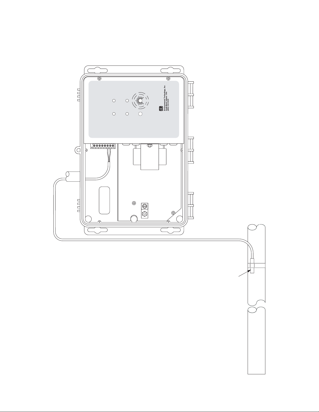
Systems using self-limiting heaters require two temperature sensors. Figure 3 shows
Monitor Temperature Sensor Control Temperature Sensor
Low Voltage
Compartment
J1
TRACON
GFEP
FAULT
HEATER
FAULT
GFEP
®
–
GPT
3
RESET
50
10
TEST
5
41
Temperature
®
http://www.networketi.com
e-mail: helpdesk@networketi.com
®
SUPPLY
HEATER
59
15
20
25
77
°C
°F
We Manage Heat
68
®
Page 12 of 21
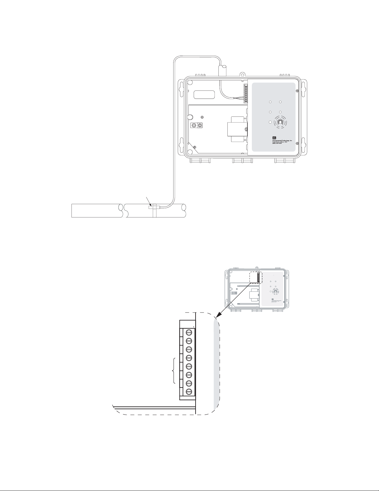
Figure 3. Control and monitor sensor connections for self-limiting heaters
Page 13
J1
®
3
N
®
G
FAULT
SU
G
RES
ST
20
15
68
9
25
10
5
50
1
C
We Manage Heat
®
http
m
®
A
A
A
Low Voltage
Compartment
HEATER
Control Temperature Sensor
Figure 4. Control sensor connection for constant wattage heaters
GPT
TRACON
GFEP
FAULT
FAULT
RESET
GFEP
TEST
®
–
3
®
SUPPLY
HEATER
59
15
50
68
20
10
5
25
77
41
°C
°F
Temperature
®
We Manage Heat
http://www.networketi.com
e-mail: helpdesk@networketi.com
®
J1
GPT
TRACO
FEP
PPLY
FAULT
5
ET
FEP
TE
77
4
Temperature
://www.networketi.co
e-mail: helpdesk@networketi.com
J1
larm Relay ----------larm Relay --
Normally Closed
larm Relay ----
Common
Normally Open
Sensor Connections
Ground
Figure 5. Alarm relay connections
Page 13 of 21
Page 14

connection of the two sensors. The GPT–3 comes factory set for self-limiting cable.
Systems using constant-wattage heaters require only one sensor as is shown in Figure 4.
Upon completion of the installation, dispose of the unused sensor.
Alarm Relay Contacts
Figure 5 shows the alarm relay connections. The relay contacts are rated for one amp in
NEC Class 2 service. Contact Customer Service if higher voltage operation is required.
Setup
Factory Settings
The GPT–3 comes set for the most common systems. This includes:
• Self-limiting cable
• GFEP set at 30 mA
• GFEP set for manual reset
The factory DIP switch settings follow:
FACTORY SETTINGS
Pole 1 2 3 4 5 6
Setting Off Off Off Off --- ---
Page 14 of 21
O
N
OFF
Figure 6. DIP switch detail
ONOFF
1
2 3 4 5 6
1
2 3 4 5 6
Page 15
J1
®
–
GPT
TRACON
3
®
GFEP
FAULT
HEATER
FAULT
GFEP
RESET
TEST
SUPPLY
HEATER
59
15
50
http://www.networketi.com
e-mail: helpdesk@networketi.com
10
5
41
°C
°F
Temperature
®
We Manage Heat
68
20
25
77
®
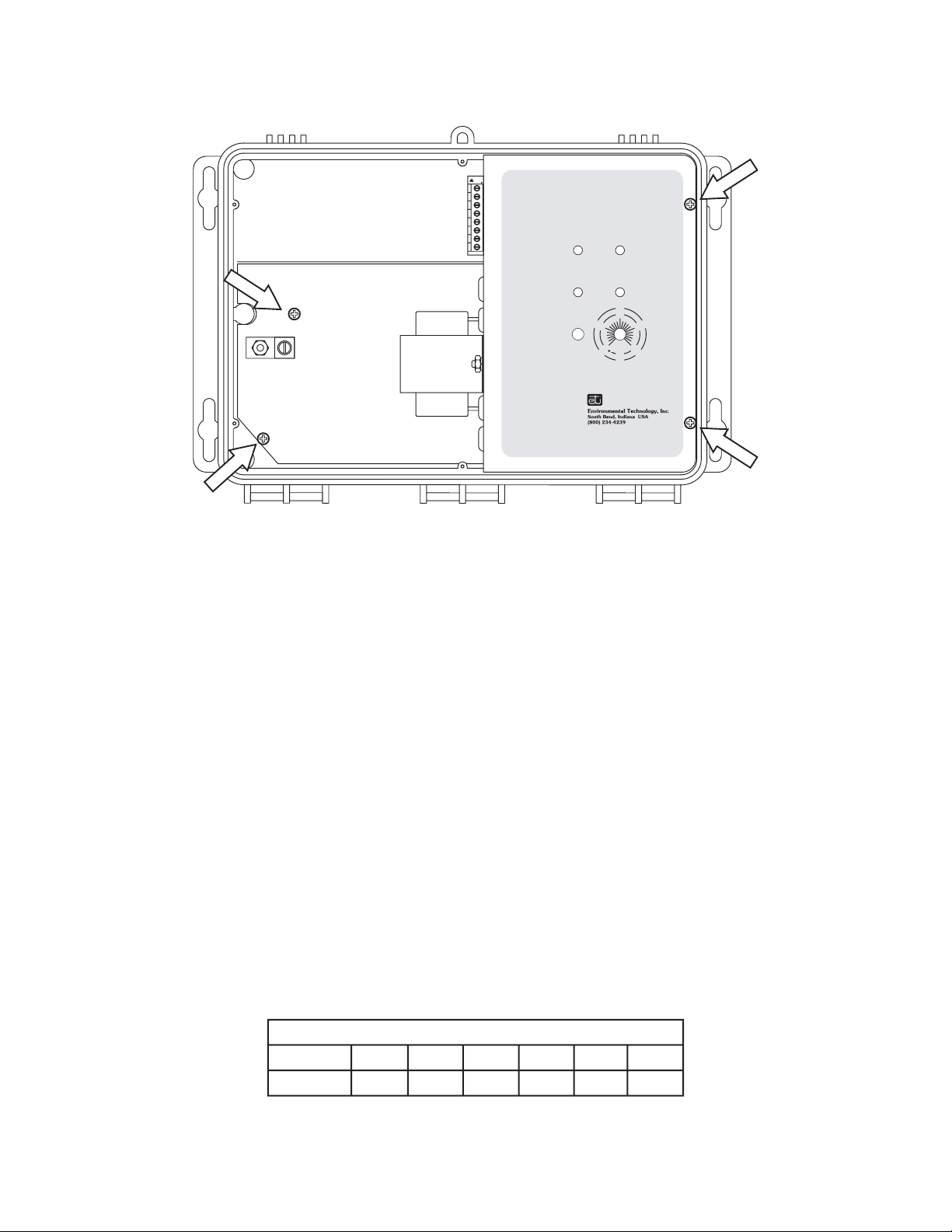
Figure 7. Removing electronic assembly from housing
Custom Settings
General
The performance of the GPT–3 can be adjusted to match the needs of the application
using the DIP switch as shown in Figure 6. Accessing this switch usually requires removing
the electronic assembly from its housing. Figure 7 shows the screws that need to be removed to
access the DIP switch.
Make any DIP switch changes before making the supply voltage and heater connections.
Otherwise, it will probably be necessary to break and re-make these connections.
DIP switch poles that do not require change are labeled ‘NC’. Spare switch poles are
labeled ‘---’.
GFEP
Mode
Fire protection sprinkler and certain other critical applications consider GFEP secondary in
importance to freeze protection. The GPT–3 accommodates these applications by warning of a
ground fault condition while it exists. Heaters operate independent of the ground fault condition.
Automatic GFEP Reset Setting
Pole 1 2 3 4 5 6
Setting On NC NC NC --- ----
Page 15 of 21
Page 16
Current
The GFEP current setting can be increased from its factory set 30 mA value to 120 mA in
30 mA steps. The higher current settings serve the special purpose of eliminating spurious GFEP
tripping. Accessing this function was made intentionally difficult to prevent its casual use. The
DIP switch settings follow:
60 mA GFEP Setting
Pole 1 2 3 4 5 6
Setting NC NC On Off --- ---
90 mA GFEP Setting
Pole 1 2 3 4 5 6
Setting NC NC Off On --- ---
120 mA GFEP Setting
Pole 1 2 3 4 5 6
Setting NC NC On On --- ---
Constant Wattage Heater Mode
The GPT–3 provides a special operating mode for checking the continuity of constant
wattage heaters. The DIP switch setting is shown below:
Constant Wattage Heater Setting
Pole 1 2 3 4 5 6
Setting NC On NC NC --- ---
Page 16 of 21
Page 17

Maintenance
General
The GPT–3 does not require routine maintenance. It contains no field replaceable
components.
Troubleshooting
The GPT–3 provides extensive fault diagnosis capability for the purpose of quickly
identifying and correcting system problems. Front panel indicators perform multiple functions
so as to provide the greatest amount of information. With one exception one, or more, indicators
flashing in repetitive patterns mean that a fault requiring a qualified technician for correction has
occurred.
The exception is operation of the HEATER FAULT indicator in a 50% on, 50% off pattern
when using self-limiting cable. This can occur when heaters first operate due to the time delay
between the application of power and attaining thermal equilibrium.
Detailed troubleshooting instruction can be obtained from either Customer Service or the
Environmental Technology, Inc. web site at http://www.networketi.com.
Returns
Contact Customer Service to obtain a Return Authorization before shipping anything to
Environmental Technology, Inc. Otherwise, the shipment may be refused.
Page 17 of 21
Page 18
Appendix A. GPT–3 dimensional drawing.
"
16
/
5
2
(59mm)
"
2
/
1
5
"
8
/
1
9
(140mm)
(232mm)
L
C
"
16
/
9
6
(167mm)
L
C
2"
(51mm)
" (21mm)
4
/
3
Conduit Entry
J1
®
3
–
®
GPT
Low Voltage
SUPPLY
TRACON
GFEP
FAULT
Compartment
®
77
20
25
HEATER
FAULT
HEATER
°F
156859
°C
We Manage Heat
5
Temperature
®
41
10
50
RESET
TEST
GFEP
http://www.networketi.com
e-mail: helpdesk@networketi.com
"
8
/
1
2
(54mm)
"
L
C
2
/
1
11
12"
(292mm)
(305mm)
4"
(102mm)
High Voltage
Compartment
" (21mm)
4
/
3
Conduit Entry
Page 18 of 21
Grounding Lug
Page 19

Appendix B. GPT–3 wiring diagram.
®
77
20
25
°F
156859
10
50
RESET
GFEP
5
TEST
°C
41
Temperature
We Manage Heat
®
http://www.networketi.com
e-mail: helpdesk@networketi.com
J1
®
3
–
®
GPT
TRACON
SUPPLY
GFEP
HEATER
FAULT
FAULT
HEATER
From 120, 208,
240, or 277 VAC
Supply
Neutral/L2
Ground
Line/L1
.
To Heater
Safety
Ground
30 Amp Load Max
Equipment
Ground
Heater Shield
Page 19 of 21
Page 20

Appendix C. Control and monitor sensor connections for self-
limiting heaters.
®
77
20
25
°F
156859
°C
5
10
50
TEST
RESET
GFEP
FAULT
We Manage Heat
Temperature
®
41
http://www.networketi.com
e-mail: helpdesk@networketi.com
®
J1
®
3
–
GPT
TRACON
Low Voltage
Compartment
GFEP
SUPPLY
HEATER
FAULT
HEATER
Page 20 of 21
Monitor Temperature Sensor Control Temperature Sensor
Page 21
Appendix D. Control and monitor sensor connections for
constant wattage heaters
®
77
20
25
°F
156859
°C
Temperature
We Manage Heat
®
http://www.networketi.com
e-mail: helpdesk@networketi.com
10
50
RESET
GFEP
TEST
5
41
J1
®
3
–
®
GPT
TRACON
GFEP
SUPPLY
HEATER
FAULT
FAULT
HEATER
Low Voltage
Compartment
Control Temperature Sensor
Page 21 of 21
 Loading...