

Page 1
FCS 13 Repair Kit Installation Instruction
Item
Qty
Description
A
2
B
6
C
4
D
1
E
1
Installation, Operation and Maintenance Instructions
IMPORTANT: Save These Instructions!
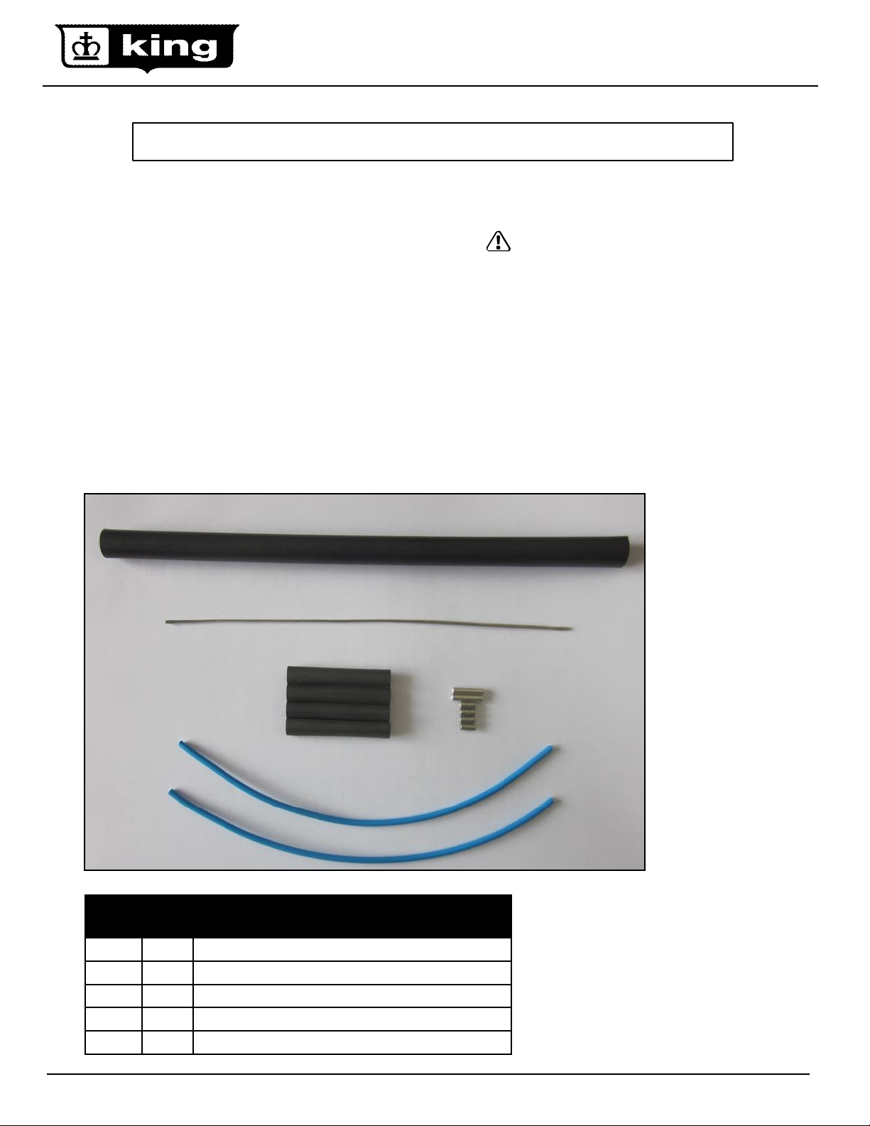
Description
The repair kit is for repairing heating cable that is damaged
during installation of the heating cable/mat. The kit includes
jumper wires to bridge the heating element after the damaged
section is removed. The kit contents are sufficient to repair one
damaged section up to 5 inches long. If more than 5 inches of
cable has been damaged, the mat must be replaced.
Tools Required
• Wire Strippers 16-26 AWG
• Gloves
• Scissors
• Crimp tool
• Heat gun
• Multimeter (capable of 200K ohms)
E
D
WARNING: ELECTRIC SHOCK HAZARD
Disconnect all power before installing or servicing
the heating cable and accessories. FC heating
cable must be grounded properly in accordance
with the National Electrical Code (NEC). Failure to
comply can result in personal injury or property
damage. Only a qualified licensed electrical
contractor shall install and service of FC heating
cable and accessories, otherwise the warranty is
voided.
Note:·All electrical wiring, including Ground Fault
Circuit Interrupters (GFCI), must be done according
to the NEC and local codes by a qualified installer.
www.king-electric.com 1
A
C
Jumper wires
Connectors
Small heat shrink tubing
Ground Wire (non-insulated)
Large heat shrink tubing
B
Rev 11.01.12
Page 2
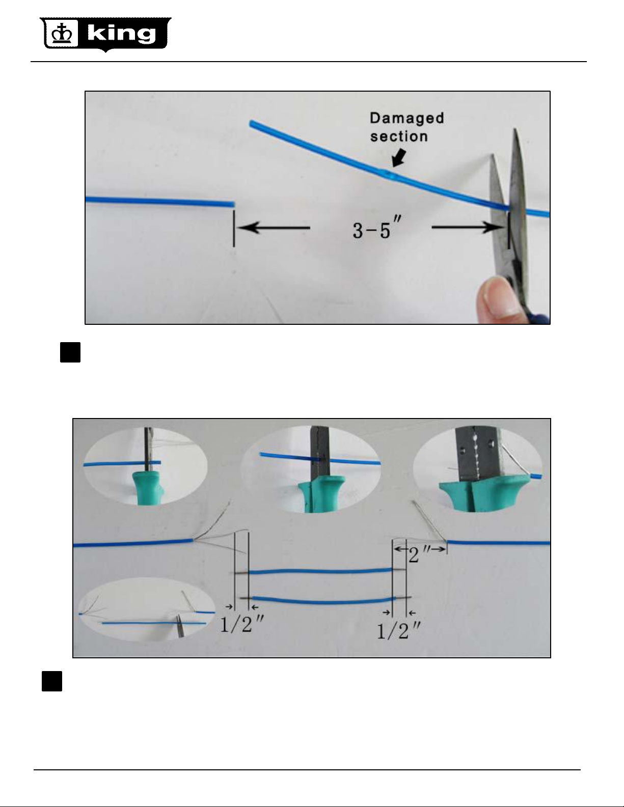
Remove at least 3-5 inches of heating cable including the damaged section leaving two protruding ends of heating
1
cable.
Using wire strippers carefully strip the heating cable and the jumper wires. Slide the large heat shrink tube over the
2
heating cable to be applied with a heat gun in the last step.
www.king-electric.com 2
Rev 11.01.12
Page 3

Using the crimp tool and connectors carefully connect the heating cables to the jumper wires and don’t forget slide
3
the heat-shrinkable tubes onto each jumper wire.
Center the 4 small black heat-shrinkable tubes over the connectors and using the heat gun shrink in place.
4
www.king-electric.com 3
Rev 11.01.12
Page 4

Cut ground jumper wire to length, and using the crimp tool and connectors carefully
5
connect the ground wires to the jumper wire.
Slide the large heat shrink tube over the entire splice and apply heat until the tube has
6
completely covered the splice.
Test the heating cable resistance and compare the reading to the cable specified. Set your multimeter to
7
the 200K ohm range and test the insulation resistance, make sure the meter reads “Open” or “OL”.
www.king-electric.com 4
Rev 11.01.12
 Loading...