

Page 1
SAVE THESE INSTRUCTIONS
Heater On
+
GENERAL INFORMATION
EC2P & ECP2P Series
System Matched™ for King heaters
DANGER
ELECTRIC SHOCK OR FIRE HAZARD
READ ALL WIRE SIZING, VOLTAGE REQUIREMENTS AND SAFETY
DATA TO AVOID PROPERTY DAMAGE AND PERSONAL INJURY
!!
2-POLE
POSITIVE
OFF
SWITCH
ECP SHOWN
LO
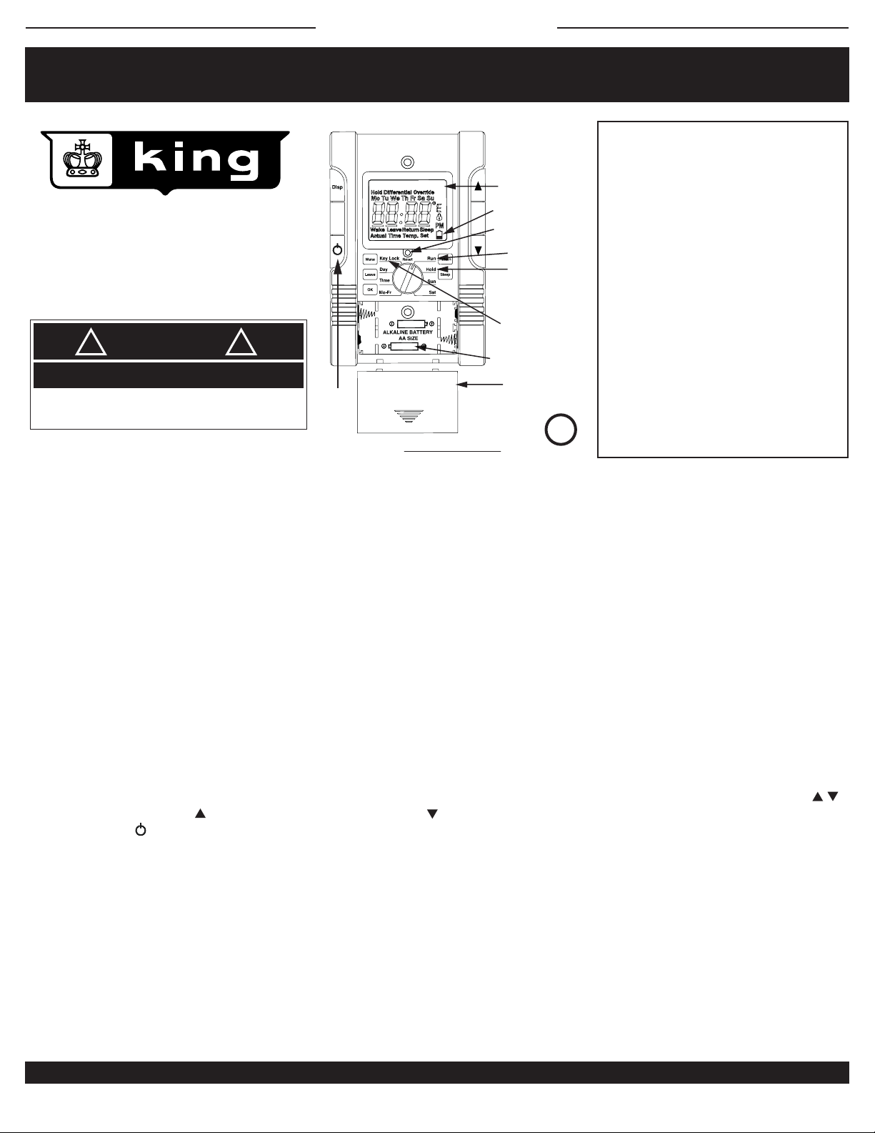
PROGRAM DRAWING #1
HEAT ON INDICATOR
LOW BATTERY INDICATOR
RESET: BACK TO PRESETS
*RUN: DAY AND TIME
*HOLD BUTTON:
RUN PROGRAM /
HOLD TEMPERATURE
*TAMPERPROOF
KEY LOCK
BATTERIES
COVER FOR BATTERIES
*ECP model only
U
®
CUS
LISTED
SPECIFICATIONS:
Temperature range: 40° to 93°F
Temperature Default: 68°F
Display Format: Liquid Crystal Display (LCD)
Display size: Large Format
Sample Rate: Every 60 seconds
Delay on or off: 3 minutes
Heat indicator: LCD “heater on”
Relay Rating: 16 Amps inductive
Relay: AA battery powered
Accuracy: ± .9°F
Maximum Amps: 16 inductive continuous
Maximum Watts: 3840 @ 240V or 1 hp
3328 @ 208V or ¾ hp
1920 @ 120V or ½ hp
Total inductive motor load combined can not
exceed 16 Amps
Minimum Watts: 0
L
Power Supply: 1 to 240 Volts AC
GENERAL INFORMATION:
This thermostat is designed to provide the best temperature control for residential line voltage electric heating. For use on 120 / 208 / 240 Volt AC and a total of
16 Amps load inductive continuous. This is a single pole thermostat with a double pole switch to disconnect both legs of power to the heater.
Almost all residential application electric heaters installed as original equipment by an electrician will be 208 or 240 Volt. It is very rare and uprofessional that a
home, apartment or condominium would be wired with all 120 Volt heaters. Check the voltage to make sure you have the right thermostat for your heater
voltage. A 2-pole or double-wide circuit breaker at the panel indicates a 240 Volt circuit; A 1-pole or single-wide breaker indicates a 120 Volt circuit. There are
some exceptions to this rule; Check with a voltmeter to determine accurate phase to phase voltage.
Be safe and smart! Electricity can cause severe injury or death if not treated with respect and caution.
This thermostat will provide years of comfort control for your family in use with small fan-driven electric heaters, baseboards, radiant ceiling or wall panel
heaters, cove heaters, or any line voltage resistance heating systems that do not have an electric motor over 1/3 hp.
OPERATION:
This precision electronic thermostat uses a very sensitive thermistor near the bottom to sense room air temperature, sending the information on to the
microprocessor. As the temperature drops, the information sent will indicate if heat is needed. To reduce any undesirable fast on/off cycles, the processor has a
built-in delay, up to 3 minutes. This saves energy and provides the best temperature control of an area.
This thermostat requires batteries and will have a one minute back-up when replacing old batteries. ECP only: The default program setting is 62°F set back,
70°F set up and a standard work week timing when powered up. The day and time of day can be adjusted by selecting the TIME position and using the
arrow keys. For an override, the UP arrow increases temperature and the DOWN arrow reduces temperature without any need to readjust the
programming. When “OFF” button is pressed the backlight will go off indicating both hot leads are disconnected.
The thermostat may take a few hours to stabilize the room temperature; Do not be alarmed when the thermostat does not show the correct temperature
immediately after installation.
INSTALLATION:
This line voltage device should be installed and serviced by a qualified electrician. The thermostat has been designed to mount to a standard 2" x 4" electrical
outlet box. King recommends a 21 cubic inch junction box for new installation. Leveling of the thermostat is not required. #6-32 Phillips head mounting screws
are provided.
Mount the thermostat in an open area about 5 feet above the floor, avoiding outside walls as they are too cold and will inhibit the thermostat’s performance. A
good rule of thumb is to place the thermostat above the wall switch for that room. This works well for most bedrooms, making it very convenient to turn the heat
lower upon leaving. Avoid mounting the thermostat where there may be plumbing pipes in the wall, or placing a lamp or TV too close to the thermostat. Heat
from such items negatively affects the thermostat’s performance.
KING ELECTRICAL MFG. CO. · 9131 - 10TH AVENUE SOUTH · SEATTLE, WA 98108 · PH: 206.762.0400 · FAX: 206.763.7738 · www.king-electric.com
ECP2P information.ai : 6/10
Page 2
SAVE THESE INSTRUCTIONS
+
Heater On
INSTALLATION AND MAINTENANCE
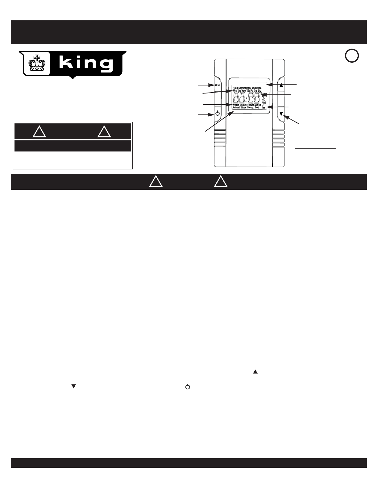
DISPLAY LEGEND - EC & ECP
EC2P & ECP2P Series
Double Pole (NOT 2-Circuit)
REPLACES MODELS: 1A66 / D22 / M602 / T498B / T4398B / MD26 /
WR661 / 1D22 / C902 / TW242 / TD902 / T410B / TD942 / M402 / M512
DANGER
ELECTRIC SHOCK OR FIRE HAZARD
READ ALL WIRE SIZING, VOLTAGE REQUIREMENTS AND SAFETY
DATA TO AVOID PROPERTY DAMAGE AND PERSONAL INJURY
!!
DISPLAY CHANGE
*DAY OF WEEK
*WAKE, LEAVE,
RETURN, SLEEP
2-POLE POSITIVE OFF
BACKLIGHTING
(backlight is off
if “OFF” button
is pushed)
WARNING
LO
!!
HEAT ON
*TIME OF DAY/
TEMPERATURE
LOW BATTERY INDICATOR
SET TEMPERATURE
UP OR DOWN
PRODUCT DRAWING #2
*ECP model only
READ CAREFULLY - These instructions were written to help prevent difficulties that may arise during thermostat
installation. Studying the instructions first may save considerable time and money later. Observing the following
procedures will keep installation time to a minimum. Save these instructions for future use.
U
L
®
CUS
LISTED
Thank you for buying this King thermostat. It should provide years of service and comfort to your home. Inspect the package. Enclosed should be the
thermostat with its cover and two screws.
1. Check the total load of the heaters being connecting to the thermostat. The maximum wattage at 240 Volt is 3840, 208 Volt is 3328, 120 Volt is
1920 and 16 Amps/480 Watts at 30 Volt DC. It is important to stay below this total wattage when connecting the thermostat. Lower wattage
prolongs the the life of the contacts in the relay.
2. To wire the thermostat determine which pair of wires are coming from the breaker panel and which pair lead to the heater.
3. Remove cover of thermostat by placing thumb on LCD display and fingers on top edge of cover. Pull towards you. This will expose the top
mounting screw. Put thumb on the lower part of the battery cover and pull down to expose mounting screw and battery compartment.
4. There may be a pair of white wires connected in your junction box. If so, leave them alone and work with the black wires. If there is only a black
wire and white wire use them - this is called a switch leg (see wiring diagram #3).
5. Take a black lead from the panel and attach it to the black lead on the thermostat. Take the white wire from the panel and attach it to the other
black lead on the thermostat.
6. Attach the black heater lead to the red thermostat lead. Take the white lead to the heater and attach to the red thermostat lead. This will provide
power to the heater when the thermostat calls for heat.
7. Push the wires carefully into the junction box making sure no wires are pinched or will obstruct the screws mounting the thermostat. Now attach
the thermostat to the wall using the #6-32 Phillips head screws provided. Replace cover. Do not over tighten screws.
8. Install AA batteries to start display. Replace cover. Batteries operate relay and display only; they are not charged by line voltage power and
should last one year. A half-filled battery shape icon saying “Lo” will appear on the LCD to indicate battery replacement is necessary.
9. Turn on power. Test by increasing set point to higher than current room temperature by tapping the Up button. There will be up to a 3 minute
delay in turning on. You will hear a small click and “Heater On” will appear in the LCD; the heater should be on now. Turn the thermostat down
by tapping on the Down arrow. (NOTE: to turn power off push the button.
10. You have now verified the thermostat is in perfect working order and ready for years of trouble-free operation.
11. Mounting tips: Make sure nothing is nearby (i.e. plumbing pipes in the wall, a lamp close by, direct sunlight, a T.V. set, and/or cold drafts from
a door opening) that could affect the average room temperature sensing of the thermostat. Typically the best, most convenient location is on
inside walls above the light switch for that room.
12. Cleaning: Canned compressed air works great to clear any dust accumulation, while a damp cloth will additionally clean the plastic case surface
of finger prints. Strong spray cleaners may damage the plastic case or remove writing or arrows screen-printed on case. Blow out any dust that
may accumulate on top or bottom air vents. Good air circulation is key to long life and accurate operation.
13. Humid locations: Mildly humid location like bathrooms may reduce life due to corrosion on the contact and lint from towels getting into
thermostat air vents. To extend life blow out vent regularly and mount thermostat away from shower locations.
KING ELECTRICAL MFG. CO. · 9131 10TH AVENUE SOUTH · SEATTLE, WA 98108 · PH: 206.762.0400 · FAX: 206.763.7738 · www.king-electric.com
ECP2P installation.ai : 6/10
Page 3

SAVE THESE INSTRUCTIONS
WIRING INSTRUCTIONS
EC2P & ECP2P Series
System Matched™ for King heaters
Double Pole Thermostat
DANGER
ELECTRIC SHOCK OR FIRE HAZARD
READ ALL WIRE SIZING, VOLTAGE REQUIREMENTS AND SAFETY
DATA TO AVOID PROPERTY DAMAGE AND PERSONAL INJURY
1. To wire the thermostat determine which pair of wires come from the breaker panel
and which pair lead to the heater.
2. Attach a black lead from the circuit breaker panel to the black lead on the
thermostat. Attach the white lead from the circuit breaker panel to the black wire on
the thermostat.
3. Attach the black lead that goes to the heater to the red lead on the thermostat.
Attach the white lead that goes to the heater to the red lead of the thermostat. This
will provide power to the heater when the thermostat calls for heat.
4. Remove thermostat cover by placing thumb on LCD display, forefinger on cover top,
pulling cover back to expose mounting screws and programming buttons. Slide
battery cover off to expose lower mounting screw.
5. Push wires carefully into the junction box making sure none are pinched or obstruct
thermostat mounting screws. Attach thermostat to wall with the #6-32 Phillips head
screws provided.
6. Hold thermostat in wallbox and place screws in top and bottom mounting hole.
Attach to wallbox. Install batteries and replace cover.
7. Turn on power. Test by increasing set point to higher than room temperature by
tapping the Up button. There will be up to a 3 minute delay turning on. You will
hear a small click and “Heater On” will appear on the LCD; the heater should now
be on. Turn the thermostat down by tapping the Down arrow.
8. Differential Adjustment: Hold both temperature and buttons for 10
seconds. The screen will go blank then show one digit. This is the number of
degrees that the thermostat will over or undershoot the desired temperature.
Adjust the setting between 1° and 4° by tapping the or arrow. Adjust to
suit your comfort level.
9. OFF: Push the button to disconnect power to heater. Backlight will turn off in
“off” position.
* To change the display from Fahrenheit to Celsius requires opening the thermostat and moving a small
jumper on circuit board. For assistance please contact the factory at (800) 603-5464 ext. 111
3 3/8" 1 1/8"
DIMENSIONS:
!!
WIRING DIAGRAM #1
1 1/8"
1 5/8"
LINE 1
WIRING DIAGRAM #3
HEATER
BLACK
COMMON WIRING
BLACK
POWER IN
BLACK
BLACK
RED
RED
BLACK
TO HEATER LOAD
COMMON
BLACK
BLACK
THERMOSTAT
RED
BLACK
HEATER - UP TO 3840 WATTS
BLACK
WHITE
BLACK
RED
WHITE
SWITCH LEG
LINE 1
BLACK
WHITE
JUNCTION
CIRCUIT
BREAKER
LINE 2
WIRING DIAGRAM #2
CIRCUIT
BREAKER
LINE 2
WHITE
WHITE
2X4
BOX
WHITE
2-Pole Positive Off
(NOT 2-Circuit)
JUNCTION BOX COVER
U
L
®
CUS
LISTED
How to wire when a switch leg
5 1/4"
15/16"
THERMOSTAT
RED
JUNCTION BOX COVER
RED
is found in the junctionbox.
KING ELECTRICAL MFG. CO. · 9131 - 10TH AVENUE SOUTH · SEATTLE, WA 98108 · PH: 206.762.0400 · FAX: 206.763.7738 · www.king-electric.com
ECP2P wiring.ai : 6/10
Page 4

ECP2P
ECP2P
Set Day and Time
Set To Run
Positive Off
Adjusting the Differential
Override Function
Your Schedule
Display Options / TAP Display Button
Batteries
1
Set Day and Time
1
Turn switch to “DAY”.
2
Use or to set day of the week.
3
Turn switch to “TIME”.
4
Use or to set hour and minute.
2
Set To Run
Wake
Leave
Return
Sleep
1
2
3
4
5
Morning wake-up program
Daily (away from home) program
Evening home program
Nightly sleep program
Turn switch to “Mo-Fr” (Monday - Friday).
Wake
Press to set first program-period of weekday.
Use or to set time for .
OK
Press to set temperature setpoint.
Use or to set temperature.
Pressing will alternate the display between
OK
Wake
Wake
time and temperature settings for all 4 buttons.
6
Leave
Press to set second program-period of
weekday.
7
Follow steps 3 - 5 to complete programming.
Return
8
Press to set third program-period of weekday.
9
Follow steps 3 - 5 to complete programming.
10
Sleep
Press to set fourth program-period of
Leave
Return
weekday.
11
Follow steps 3 - 5 to complete programming.
12
Turn switch to “SAT” (Saturday).
13
Follow steps 3 - 5 to complete Saturday
Sleep
programming.
14
Turn switch to “SUN” (Sunday).
15
Follow steps 3 - 5 to complete Sunday
programming.
SAVE THESE INSTRUCTIONS
PROGRAMMING INSTRUCTIONS
Key Lock
Wake
Day
Leave
Time
OK
Mo-Fr Sat
Key Lock
Wake
Day
Leave
Time
OK
Mo-Fr
Reset
Reset
Run
Hold
Sun
Run
Hold
Sun
Sat
Return
Sleep
Return
Sleep
Default Energy Star Schedule
Program
Wake
Leave
Return
Sleep
Wake
Leave
OK
Key Lock
Day
Time
Mo-Fr
Temp.
70°
62°
70°
62°
Reset
Mo-Su
6:00am
8:00am
6:00pm
10:00pm
Run
Return
Hold
Sleep
Sun
Sat
“ERR” will show if no data is input
after 10 minutes. To continue,
turn switch to “RUN” then back to
previous position.
Wake
Leave
OK
Wake
Leave
OK
Key Lock
Day
Time
Mo-Fr
Key Lock
Day
Time
Mo-Fr
Reset
Reset
Run
Hold
Sun
Run
Hold
Sun
Sat
Return
Sleep
Sat
Return
Sleep
3
Adjusting the Differential
1
Turn switch to “RUN” to operate.
2
Press and together for 8 seconds.
3
Use either or to set differential.
4
The thermostat will memorize and use the new
setting after 5 seconds.
4
Override Function
This thermostat provides 2 manual temperature
overrides.
TEMPORARY temperature change.
1
Turn switch to “RUN”.
2
Use or to change temperature setting.
3
The thermostat will memorize and use the new
setting after 5 seconds or until the next timetemperature begins.
4
To end the temporary override turn the switch
away from “RUN” then back.
PERMANENT on HOLD temperature setting
1
Turn switch to “HOLD”.
2
Use or to change temperature setting.
3
The thermostat will use the new setting after 5
seconds until the user manually ends it.
4
To end the permanent on hold override turn the
switch away from “HOLD” to “RUN” or “Key
Lock”.
5
Your Schedule
Monday - Friday
Program
Wake
Leave
Return
Sleep
6
Time
Display Options / TAP Display Button
Temp.
:
:
:
:
U
L
®
CUS
Reset
Suggested
Differential
1°
2°
3°
4°
Temp.
ENERGY STAR
Run
Return
Hold
Sun
Sat
Run
Return
Hold
Sleep
Sun
Sat
°F
°F
°F
°F
Sleep
LISTED
Wattage
100 to 1000W
1200 to 2000 W
2000 to 2750 W
3000 to 3840W
Key Lock
Wake
Day
Leave
Time
OK
Mo-Fr
Key Lock
Wake
Leave
OK
This deactivates buttons on the
front panel. Temperature can not
be changed without switching back
to “RUN”.
Saturday
Time
°F
°F
°F
°F
Temp.
:
:
:
:
°F
°F
°F
°F
Reset
Day
Time
Mo-Fr
Key Lock
Sunday
Time
:
:
:
:
2
Positive Off
Depressing this button disconnects both power
leads from the heater. No matter how low the
temperature gets the heater will not energize
when this button is in the down position.
The backlight turns off when the “Off” button is
depressed.
Technical support: (800) 603-5464 ext 111 / info@king-electric.com
Room Temperature / Day and Time /
1
Disp
1
Setpoint T emperature Alternating
Room Temperature Only / No Alternating.
2
7
Batteries
LCD display and relay are battery powered, not
charged by line voltage. One year life is expected.
2
“BAT LO” showing on the LCD indicates time to
replace the batteries.
ECP2P programming.ai : 6/10
 Loading...