

Page 1
AutoScan Satellite System
9630 9630-LP
Installation and Operating Instructions
11200 Hampshire Avenue South, Bloomington, MN 55438-2453
Phone: (800) 982-9920 Fax: (952) 922-8424
www.kingcontrols.com
1352 REV N
Satellite Solutions for Mobile Markets
AutoScan
®
Page 2

Page 3

Page 1
IMPORTANT!
The satellite TV market is expanding and changing. The information in this manual was
accurate at the time of printing. If your King-Dome does not operate as outlined in this
manual please call King Controls at ( 800) 982-9920 or visit our website at
www.kingcontrols.com.
TABLE OF CONTENTS
Section Contents Page
1. INTRODUCTION.....................................................................................2
2. DEFINITION OF TERMS........................................................................3
3. INSTALLATION..................................................................................4-10
4. OPERATION ....................................................................................11-15
5. STORE/RECALL POSITIONS ..............................................................16
6. DIAGNOSTICS .....................................................................................17
7. MAINTENANCE....................................................................................18
8. LIMITED WARRANTY ..........................................................................19
DIRECTV®is a registered trademark of DIRECTV, Inc.
Dish NetworkTM is an official trademark of Echostar Communications Corporation.
Bell ExpressVu is an official trademark of Bell Canada.
DVB
®
is a trademark of the DVB Digital Video Broadcast Project (1991-1996)
Page 4
Page 2
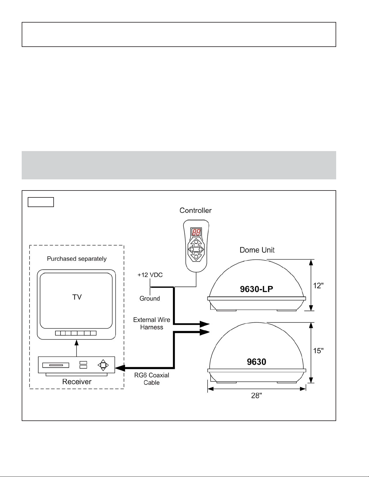
The King-Dome AutoScan Satellite System includes 2 main components (Fig. 1).
Dome (Antenna) Unit Located on the roof of the vehicle. The dish is covered by a
protective dome that keeps operational components free from
the elements.
Controller Located in the vehicle. Used to activate the system, position
the dish, and access diagnostic information.
SECTION 1
INTRODUCTION
Note: A TV, satellite receiver, and program subscription are also required for satellite TV
viewing. (Purchased separately.)
Fig. 1
Page 5
Page 3
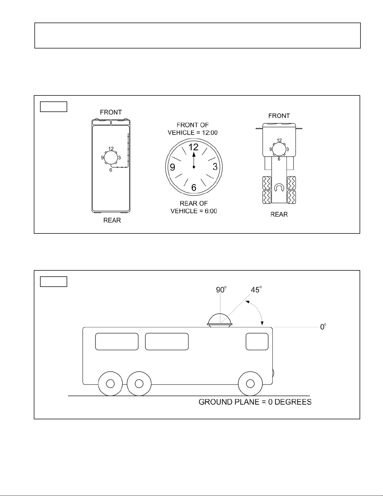
AZIMUTH: Circular rotation around the vehicle.
(like a clock face: front of vehicle is 12:00, rear is 6:00) (Fig. 2)
ELEVATION: Angle in degrees measured from the ground plane (Fig. 3).
SIGNAL STRENGTH: Intensity of electronic signal received from the satellite transmission.
SECTION 2
DEFINITION OF TERMS
Fig. 2
Fig. 3
Page 6
Page 4
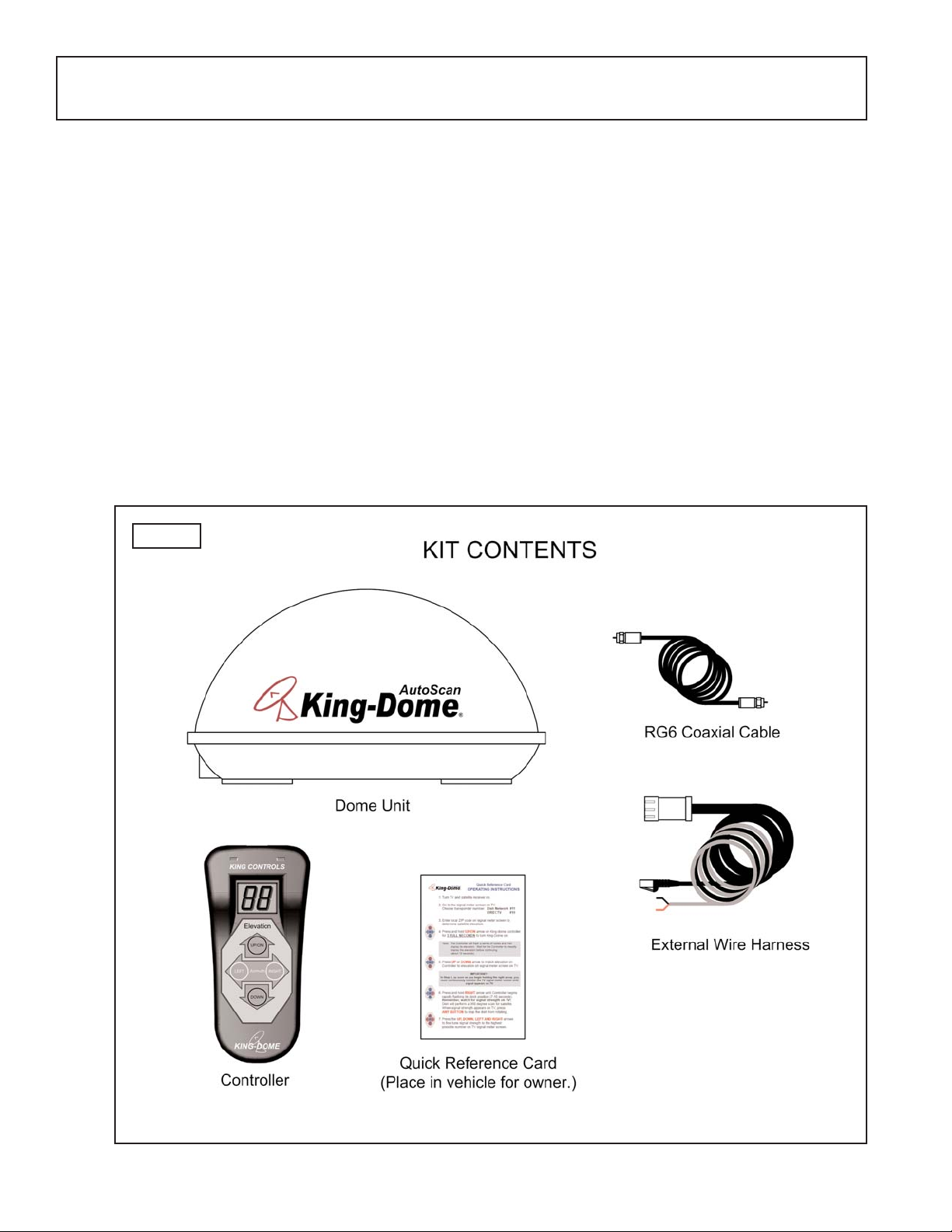
KIT CONTENTS:
1. Unpack and identify all components (Fig. 4).
SECTION 3
INSTALLATION
Fig. 4
TOOLS AND MATERIALS REQUIRED:
- drill and drill bit set
- tape measure
- 7/16” open end wrench (coax connections)
- adhesive sealant (compatible with roof material)
- appropriate fasteners to install all components and wiring
- 5/32” allen wrench, channel lock or pliers (to remove shipping bolts)
- wire cutter (to remove shipping tie strap)
Page 7
Page 5
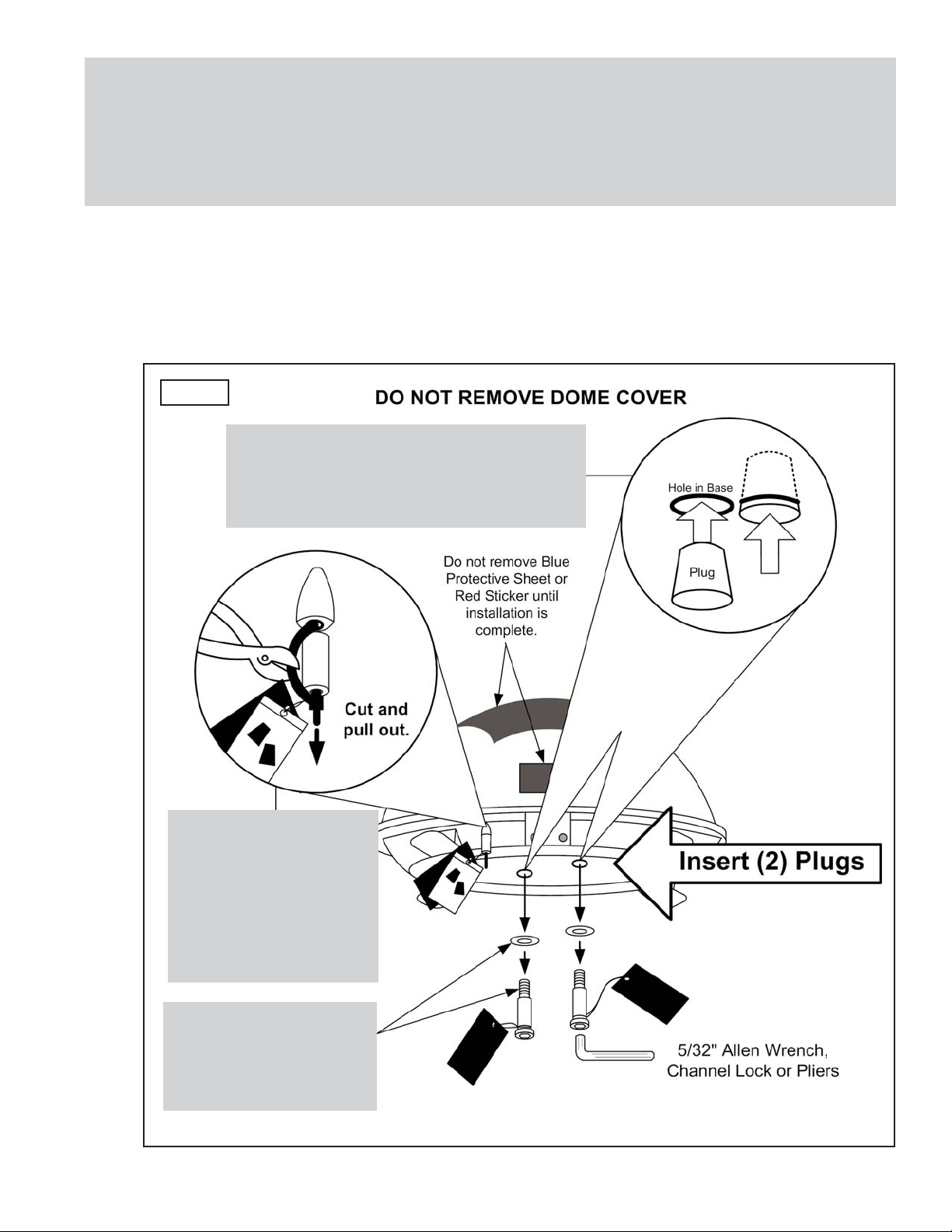
IMPORTANT! The tie strap and spacer, and the bolts and washers must be removed
from the bottom of the dome unit prior to installation. DO NOT REMOVE
THE DOME COVER TO REMOVE THESE SHIPPING RESTRAINTS.
YOU MUST PLUG THE SHIPPING BOLT HOLES WITH THE SUPPLIED
PLUGS (ATTACHED TO TIE STRAP SHIPPING RESTRAINT).
2. Remove and discard the tie strap and spacer (KEEP RUBBER PLUGS), and the (2) bolts
and (2) washers that pass through the bottom of the base (Fig. 5).
3. Insert provided plugs into holes that were occupied by the shipping bolts. Inserted plugs
should be flush with base (Fig. 5).
Fig. 5
IMPORTANT!
Remove and discard
Tie Strap and Plastic
Spacer prior to
installation.
KEEP RUBBER
PLUGS.
IMPORTANT!
Remove and discard
Bolts and Washers
prior to installation.
IMPORTANT!
After removing shipping bolts, firmly
insert plugs into holes. Plugs should
be flush with base.
Page 8
Page 6
DOME LOCATION
4. Select an area on the roof for the dome unit and the location where the wiring will enter
the vehicle through the roof to the satellite receiver, controller, and 12 volt power source
inside, using the following criteria:
a) The shortest distance between the dome unit and the satellite receiver is most
desirable.
b) The dome unit requires a 28 inch diameter mounting area.
c) The dome unit must be mounted on the centerline of the vehicle. Mounting off
centerline reduces electronic level compensation.
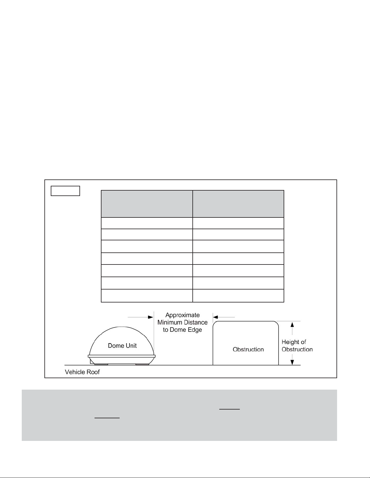
d) There must be no “line of sight” obstructions. Air conditioning units, other antennas,
and storage areas that are too close to the dome unit may prevent the satellite
signal from reaching the dish (Fig. 6).
HEIGHT OF
OBSTRUCTION
APPROXIMATE
MINIMUM DISTANCE
TO DOME EDGE
10” 8”
11” 10”
12” 12”
13” 14”
14” 16”
15” 18”
16” 20”
Fig.6
IMPORTANT! For installations on trucks with air shields, a bracket must be used for
mounting the dome unit. The dome unit MUST
be mounted to the air ride
cab: NEVER to any structure mounted directly to the frame.
See bracket instructions for proper installation (Fig. 7).
Page 9

Page 7
5. Place dome unit on installation location chosen using the criteria discussed in the
previous section. Shipping restraints must be removed (Fig. 5, Page 5), and cable
connections must ALWAYS
be positioned facing rear of vehicle.
6. The dome unit must be positioned so that both feet on each side of the vehicle are equal
distances from the roof edge. This should be checked by measuring the distance from
each foot to the roof edge. Confirm that these measurements are equal (Fig. 8).
IMPORTANT! Make sure shipping restraints are removed from bottom of dome unit
(Fig. 5, Page 5).
Cable connections must AL
WAYS be positioned facing the rear of vehicle.
Example of truck installation using bracket.
See bracket instructions for proper installation.
Fig. 8
Fig. 7
IMPORTANT! The dome unit MUST
be mounted to the air ride cab: NEVER to any structure
mounted directly to the frame.
DOME INSTALLATION
IMPORTANT! The dome should never be mounted so that it is tilted more than 2 degrees
in any direction.
IMPORTANT!
Cable connections
must always face
REAR of vehicle.
Page 10

Page 8
7. Mount the dome unit. Use the pre-drilled holes in the mounting feet as a guide to install
the fasteners into the roof. Use additional fasteners whenever necessary.
8. Test that the dome unit is secure by pulling upward from each foot location.
EXTERNAL WIRING
9. Plug external wire harness into wiring port on back of dome unit and tighten connection
until it clicks past the detent lock (Fig. 9).
10. Connect coax cable to coax port labeled MAIN on back of dome unit and tighten
connection. If using a second receiver, connect second coax cable to coax port labeled
AUX and tighten connection. Do not over tighten coax connections (Fig. 9).
Note: The installer is responsible for determining the most appropriate fastener to secure the
dome unit to the roof. Depending on the roof material, fasteners such as lag screws,
well nuts, sheet metal screws, toggle bolts and T anchors may be used, and should
always be used in combination with a roof compatible sealant.
IMPORTANT! The installer is responsible for weather proofing all holes with sealant.
Note: The King-Dome is wired for a dual LNB. There are two coaxial ports on the back of the
dome unit. The one labeled “MAIN” MUST be connected to the main receiver in vehicle.
The one labeled “AUX” can be used for an additional receiver.
IMPORTANT! Do not remove the rubber sleeves from the coax ports. The coax cable
ends will slide inside the sleeves as they are tightened.
Fig. 9
IMPORTANT!
Coax connections will slide inside
rubber sleeves.
Coax connections should be snug.
DO NOT OVER TIGHTEN!
IMPORTANT!
The alignment tabs on the
wiring port and the external
wire harness plug must
match up when engaging
plug
onto port.
YOU MUST
TIGHTEN THE
PLUG UNTIL IT CLICKS
PAST THE DETENT LOCK.
(A channel lock pliers may
be used to tighten the
connection.)
Page 11

Page 9
11. Run wires from the back of the dome unit to the roof edge, then along edge to location
where wiring will be fed into the vehicle. (If installing an optional second receiver, run
auxiliary coax to location where it will enter the vehicle.) Secure wiring to roof every
12-18 inches (Fig. 10).
12. Drill 3/4” hole through the roof and into the cabinet where receiver is stored. Feed wiring
down through hole. Seal opening with roof compatible sealant so that it is entirely
waterproof (inside and outside of the 3/4” hole). Repeat for optional second receiver
(Fig. 10).
13. Remove blue protective sheet and red “position to rear” sticker from the dome unit.
Fig. 10
TYPICAL ROOF INSTALLATION - OVERHEAD VIEW
IMPORTANT!
Sealant must
be roof
compatible.
Page 12

Page 10
14. Inside vehicle, connect main coax from the dome unit directly to the “satellite in” port of
the main receiver. Do not go through an “A-B” or any other switch, box, or booster.
Connect auxiliary coax directly to optional second receiver.
15. Connect red and black two conductor wire to a power source and ground. Red connects
to +12 volts, and black connects to ground.
16. Plug phone style Controller Cable into Controller.
IMPORTANT: The connection between the dome unit and the receiver must be a direct
connection with no devices in between. Any other devices should be
downstream from the receiver.
IMPORTANT: Power connection must be a non-shared circuit. Excessive current draw
on the circuit will cause the unit to operate improperly. Power and ground
connections must be made after the wires are connected to the dome unit.
INTERNAL WIRING
Page 13

Page 11
SECTION 4
OPERATION
1. Turn TV and satellite receiver on.
2. Go to the signal meter screen on TV.
Choose transponder number: Dish Network #11
DIRECTV #19
3. Enter local ZIP code on signal meter screen to determine satellite
elevation. If you do not know your local zip code, determine your
elevation from the maps on pages 12-14.
4. Press and hold UP/ON arrow on King-Dome Controller for
3 FULL
SECONDS
to turn King-Dome on.
5. Press UP or DOWN arrow on King-Dome Controller to match
elevation on Controller to elevation on TV signal meter screen or
elevation from maps on pages 12-14.
6. Press and hold RIGHT arrow until Controller begins RAPIDL
Y
flashing its clock position (7-10 seconds). (See Fig. 2, Page 3.)
Remember, you must watch for signal strength on TV!
Dish will automatically perform a 360 degree scan for satellite.
When signal strength appears on TV, press ANY BUTTON to stop
the dish from rotating.
7. Press the UP, DOWN, LEFT or RIGHT arrows to fine tune signal
strength to the highest possible number on TV signal meter screen.
Enjoy your programming!
IMPORTANT! There must be a clear “line of sight” to the southern sky. Mountains,
buildings, trees, telephone poles, etc. can all block the satellite signal
from reaching the dish.
IMPORTANT! In Step 6, as soon as you begin holding the right
arrow, you must continuously monitor the TV
signal meter screen until signal appears on TV.
Note: The Controller will flash a series of codes and then display its
elevation. Wait for the Controller to steadily display the
elevation before continuing (about 10 seconds).
Page 14

Page 12
Elevation Map for DIRECTV 101
Find your location on the map. Use the elevation lines to determine your approximate elevation.
Page 15

Page 13
Elevation Map for Dish/DIRECTV 110
Find your location on the map. Use the elevation lines to determine your approximate elevation.
Page 16

Page 14
Elevation Map for Dish/DIRECTV 119
Find your location on the map. Use the elevation lines to determine your approximate elevation.
Page 17

Page 15
While the dish rotates, the direction of the dish in relation to the vehicle’s
position will be displayed on the controller as a clock number.
(The windshield is always 12:00 o’clock: see Fig. 2, Page 3.)
This information can be used to determine when the dish is close to
pointing at the desired satellite.
IMPORTANT! You must continuously monitor the TV for signal strength while the
dish is rotating. DO NOT WATCH THE KING-DOME CONTROLLER.
Page 18

Store Satellite Position #1
1. Once locked onto a desired satellite, hold LEFT AND RIGHT
arrows simultaneously until display flashes.
2. Hold LEFT arrow until 1P (Position 1) appears on display.
Position #1 is stored in memory for this position.
Store Satellite Position #2
3. Once locked onto the second desired satellite, hold
LEFT AND RIGHT arrows simultaneously until
display flashes.
4. Hold RIGHT arrow until 2P (Position 2) appears on display.
Position #2 is stored in memory for this position.
Recall Satellite Position #1
5. Press DOWN AND LEFT arrows simultaneously.
Dish will automatically move to Satellite Position #1 and
controller will display 1P.
Recall Satellite Position #2
6. Press DOWN AND RIGHT arrows simultaneously.
Dish will automatically move to Satellite Position #2 and
controller will display 2P.
SECTION 5
STORE/RECALL POSITIONS
Note: For use with multi-satellite services (such as Dish 500).
Page 16
Page 19

Page 17
SECTION 6
DIAGNOSTICS
Page 20

Page 18
The King-Dome Satellite System has been designed to be maintenance and trouble free.
For optimum signal strength, keep the dome clean from dirt, bugs, and other debris. Periodic
washing of the dome with mild soap and water is recommended.
If you plan on storing your vehicle for long periods of time, it is recommended that the system be
put through a search procedure on a quarterly basis to keep all moving parts in good working
order.
If you have any comments or questions, please contact the King Controls Service Department at
(800) 982-9920, or email King Controls at info@kingcontrols.com
Rain Fade
Rain or dew on the dome can cause signal interference and make the digital picture freeze, pixel
or go out altogether. This loss of signal is commonly referred to as “rain fade” and is caused by
the combination of water in the atmosphere and water on the dome surface.
To minimize this issue and eliminate the effects of water on the dome, apply King Controls
Dome Magic
®
rain fade solution to the dome. This will prevent water from sticking to the dome
surface and blocking the signal. For additional details on Dome Magic®rain fade solution please
contact your authorized King-Dome dealer or call King Controls at (800) 982-9920.
SECTION 7
MAINTENANCE
Note: Dome Magic®will discolor black domes or domes painted a dark color.
Single Application Packet #1830-SP Spray Can #1830
Page 21

Page 19
Every King Controls Satellite System is thoroughly inspected and tested before leaving the factory. It is covered by
a two year parts and one year labor limited warranty from the date of original purchase. This warranty does not
cover installation and external wiring or refurbished units.
Should any trouble develop during the warranty period, contact King Controls or one of its certified dealers. Only
King Controls and certified dealers are authorized to perform warranty evaluations and repairs.
If it is determined that the unit needs to be returned, return COMPLETE product, freight prepaid, to :
King Controls, 11200 Hampshire Avenue South, Bloomington, MN 55438-2453. If inspection shows the trouble
is caused by defective workmanship or material, King Controls will repair (or at its option, replace) without charge.
This warranty does not apply where:
- The product has been abused, misused, improperly installed or improperly maintained.
- Repairs have been made or attempted by others who are not certified by King Controls to do such repairs.
- Repairs are required because of normal wear and tear.
- Alterations have been made to the product.
In no event shall King Controls be liable for any indirect, incidental, or consequential damages from the
sale or use of the product. This disclaimer applies both during and after the term of the warranty.
King Controls disclaims liability for any implied warranties, including implied warranties of
“merchantability” and “fitness for a specific purpose,” after the one year term of this warranty.
This warranty gives you specific legal rights, and you may also have other rights, which vary from state to state.
Some states do not allow the exclusion or limitation of incidental or consequential damages, so the above limitation
or exclusion may not apply to you. Some states do not allow limitations on how long an implied warranty lasts, so
the above limitation may not apply to you.
SECTION 8
LIMITED WARRANTY
Page 22

Page 20
Notes
Page 23

Page 24

11200 Hampshire Avenue South, Bloomington, MN 55438-2453
Phone: (800) 982-9920 Fax: (952) 922-8424
www.kingcontrols.com
AutoScan
 Loading...