

Page 1
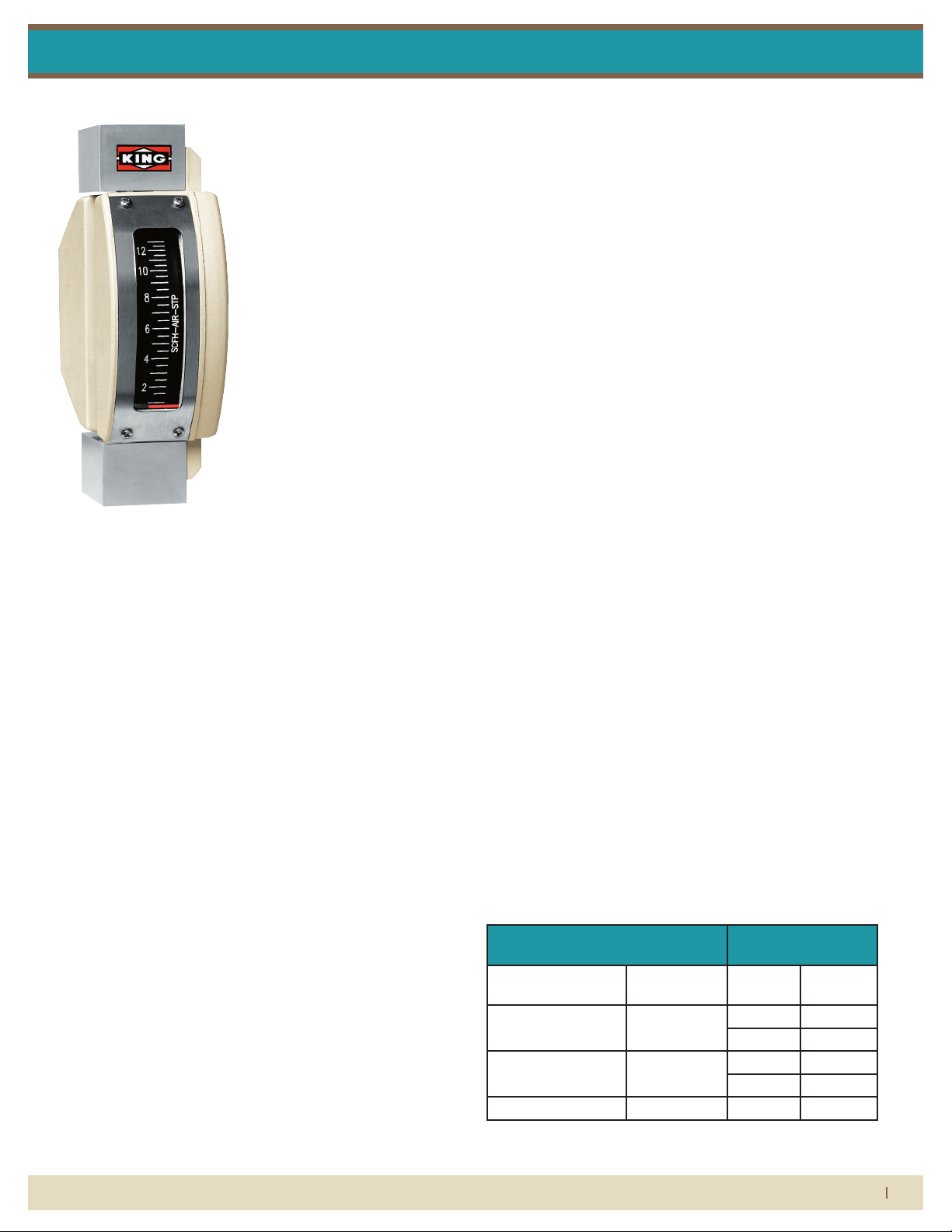
7100 Series
Installation Instructions
FLOW METER LIMITED WARRANTY
Meters are warranted against defects in materials and workmanship to the original user for a period of thirteen (13) months from the date of factory shipment, provided the meter is installed, operated and maintained
in accordance with King Instrument Company’s instructions and recommendations.
This warranty does not apply if failure is caused or contributed to by any of the following: improper handling,
improper storage, abuse, unsuitable application of the product, lack of reasonable and necessary maintenance, use exceeding suggested pressure and temperature maximums, improper packaging for return, or
repairs made or attempted to be made by anyone other than King Instrument Company, Inc.
KING INSTRUMENT COMPANY, INC. MAKES NO WARRANTY AS TO THE FITNESS OF ITS PRODUCTS FOR SPECIFIC
APPLICATIONS.
This warranty is valid for the original end-user only and does not apply to products that have been damaged
or modied. This warranty is non-transferrable and is limited to replacement or repair. The liability of King Instrument Company arising out of its supply of the products, or their use, shall not in any case exceed the cost
of correcting defects in the products as set forth above.
THIS WARRANTY IS A LIMITED WARRANTY AND SHALL BE IN LIEU OF ANY OTHER WARRANTIES, EXPRESSED OR
IMPLIED, INCLUDING BUT NOT LIMITED TO ANY IMPLIED WARRANTY OR MERCHANTABILITY OR FITNESS FOR A
PARTICULAR PURPOSE. THERE ARE NO OTHER WARRANTIES WHICH EXIST BEYOND THE DESCRIPTION OR FACE
HEREOF.
IN NO EVENT SHALL KING INSTRUMENT COMPANY BE LIABLE FOR LOSS OF PROFITS, INDIRECT, CONSEQUENTIAL OR INCIDENTAL DAMAGES.
Products should be returned, prepaid, to King Instrument Company, Inc. with proof of purchase. Call factory
for Return Merchandise Authorization (RMA) number and return instructions.
THIS IS IMPORTANT INFORMATION.
READ IT CAREFULLY BEFORE BEGINNING WORK.
1) Inspect meter for damage that may have occurred during shipping.
Report any damage to the container to the freight carrier immediately.
2) Make sure your pressure, temperature, uid and other requirements
are compatible with the meter including o-rings (where applicable).
3) Select a suitable location for installation to prevent excess stress on
the meter which may result from:
a) Misaligned pipe.
b) The weight of related plumbing.
c) “Water Hammer” which is most likely to occur when ow is
suddenly stopped as with quick closing solenoid operated
valves. (If necessary, a surge chamber should be installed. This will
also be useful in pressure start-up situations.)
d) Thermal expansion of liquid in a stagnated or valve
isolated system.
e) Instantaneous pressurization which will stress the meter and
could result in tube failure.
NOTE: In closed thermal transfer or cooling systems, install the
meter in the cool side of the line to minimize meter expansion and
contraction and possible uid leaks at the threaded connections.
4) Handle the meter carefully during installation.
a) Use an appropriate amount of teon tape on external pipe
threads before making connections. Do not use paste or stick type
thread sealing products.
5) Install the meter vertically with the inlet port at the bottom.
6) Meters with stainless steel ttings will support several feet of pipe
as long as signicant vibration or stress resulting from misaligned pipe
are not factors.
ADDITIONALLY:
• 7100 Series meters are designed for vertical installation only. (Inlet at
bottom, Outlet at top)
• Do not remove or adjust the screws on the side of the indicator
housing. These screws were positioned during factory calibration
and represent the zero adjustment. If these screws are loosened and
the indicator housing is moved, the scale will be out of accuracy.
Caution: Zero is factory set when meter is calibrated. DO NOT
loosen screws that fasten indicator housing to meter body. If
indicator housing is moved, the meter will need to be calibrated.
Maximum Non-Shock Pressure and
Temperature
Non-valve 4,000 psig O-Ring
Inlet / Outlet Valve 1,500 psig EPR 225° F
Ambient temperature -40° F - 125° F Viton® 350° F
Viton® and Kalrez® are registered trademarks of DuPont Dow
Elastomers.
O-Ring Temperature
Max Temp
Material
Buna-N 275° F
Kalrez® 400° F
No O-Ring 400° F
When it comes to ow...we’re instrumental.
(714) 891-0008 • www.kinginstrumentco.com
1
Page 2
7100 Series
2X
SCALE PLATE
POINTER ASSEMBLY
POINTER ASSEMBLY
CASE COVER GASKET
CASE COVER
CASE COVER
2X
4X
FOLLOWER DISC/
SCREW
SCREW
POINTER ASSEMBLY
POINTER ASSEMBLY
CASE COVER GASKET
CASE COVER
CASE COVER
FOLLOWER DISC/
SCREW
SCREW
VALVE O-RING
VALVE ASSEMBLY
2X
2X
2X
4X
TOP PLUG
OUTLET FLOAT STOP
FLOAT
METER TUBE ASSEMBLY
CASE ASSEMBLY
SCREW
2X
REAR CASE SCREW PLUG
SCALE PLATE
POINTER ASSEMBLY
POINTER ASSEMBLY
CASE COVER GASKET
CASE COVER
CASE COVER
2X
4X
FOLLOWER DISC/
METER TUBE ASSEMBLY
SCREW
SCREW
Installation Instructions
CAUTION
• O-rings should be replaced if meter is disassembled after it has been
in service.
• Serious property damage and great personal injury could occur as
the result of a meter misused or used in an unsuitable application.
CLEANING
Carefully remove the owmeter from piping system. Remove the
threaded outlet plug and withdraw the oat from the top. All necessary instrument components are now fully accessible for cleaning with
a bottle brush and appropriate mild soap solution*. Before the meter is
reassembled, inspect all parts for damage. O-rings should be replaced
during meter maintenance and cleaning.
To reassemble, carefully guide the magnetic oat back into the tube.
Reinstall and tighten top plug in appropriate port. Reinstall the instrument into the plumbing system after removing the old teon tape
(with a wire brush) and replacing with fresh teon tape.
*Do not use cleaning agents that will damage oat, tube or o-rings.
Meters should be cleaned with a mild soap solution. This will be an
eective cleaner of rust stains. Caution must be used so that materials
of construction are not damaged by cleaning solutions. Hard water
deposits can be removed with 5% acetic acid solution (vinegar).
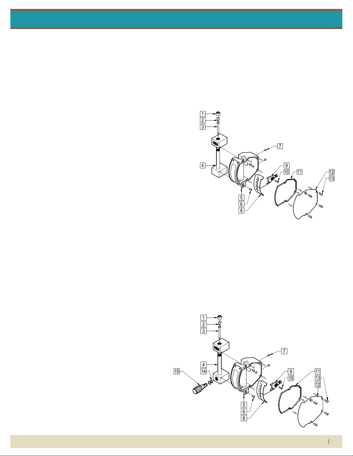
7100 SERIES ASSEMBLY NON VALVE
PARTS LIST:
1. Top Plug
2. Outlet Float Stop
3. Float
4. Meter Tube Assembly
5. Case Assembly
6. Meter Tube Assembly
Screw
7. Rear Case Screw Plug
8. Scale Plate
9. Follower Disc/ Pointer
Assembly
10. Pointer Assembly Screw
11. Case Cover Gasket
12. Case Cover
13. Case Cover Screw
REPAIR
7100 meters that require repair should be sent to the factory. Please
call for a Return Merchandise Authorization (RMA) number and return
instructions.
WARNING:
Pressure and temperature ratings are based on a study of the engineering data for particular materials used in construction and on the
design of individual models. This information is supplemented by
destructive test results. Meters with stainless enclosures must never be
operated without shields securely in place. Meters exposed to dicult
environments such as those created by certain chemicals, excessive
vibration or other stress inducing factors could fail at or below the
suggested maximums. Never operate meters above pressure and
temperature maximums. It is strongly recommended that all meter
installations utilize an appropriate pressure relief valve and/or rupture
disc. The pressure settings and locations of these devices should be
such that meters cannot be over pressurized. Meter failure could
result in damage to equipment and serious personal injury. Always
use suitable safety gear, including OSHA approved eye protection
when working around meters in service. We are happy to pass along
chemical compatibility information that has been published by the
manufacturer’s of raw materials used in our products; however, this
information should not be construed as a recommendation made by
King Instrument Company, Inc. for a specic application.
7100 SERIES ASSEMBLY WITH INLET VALVE
PARTS LIST:
1. Top Plug
2. Outlet Float Stop
3. Float
4. Meter Tube Assembly
5. Case Assembly
6. Meter Tube
Assembly Screw
7. Rear Case Screw Plug
8. Scale Plate
9. Follower Disc/
Pointer Assembly
10. Pointer Assembly
Screw
11. Case Cover Gasket
12. Case Cover
13. Case Cover Screw
14. Valve O-Ring
15. Valve Assembly
When it comes to ow...we’re instrumental.
(714) 891-0008 • www.kinginstrumentco.com
2
Page 3

7100 Series
12700 Pala Drive, Garden Grove, CA 92841
www.kinginstrumentco.com / (714) 891-0008
Meters are warranted against defects in materials and workmanship
to the original user for a period of thirteen (13) months from the date
of factory shipment, provided the meter is installed, operated and
maintained in accordance with King Instrument Company's
instructions and recommendations.
This warranty does not apply if failure is caused or contributed to by
any of the following: improper handling, improper storage, abuse,
unsuitable application of the product, lack of reasonable and
necessary maintenance, use exceeding suggested pressure and
temperature maximums, improper packaging for return, or repairs
made or attempted to be made by anyone other than King Instrument
Company, Inc.
KING INSTRUMENT COMPANY, INC. MAKES NO
WARRANTY AS TO THE FITNESS OF ITS PRODUCTS
FOR SPECIFIC APPLICATIONS.
This warranty is valid for the original end-user only and does not
apply to products that have been damaged or modified. This
warranty is non-transferrable and is limited to replacement or repair.
The liability of King Instrument Company arising out of its supply of
the products, or their use, shall not in any case exceed the cost of
correcting defects in the products as set forth above.
THIS WARRANTY IS A LIMITED WARRANTY AND
SHALL BE IN LIEU OF ANY OTHER WARRANTIES,
EXPRESSED OR IMPLIED, INCLUDING BUT NOT
LIMITED TO ANY IMPLIED WARRANTY OR
MERCHANTABILITY OR FITNESS FOR A PARTICULAR
PURPOSE. THERE ARE NO OTHER WARRANTIES
WHICH EXIST BEYOND THE DESCRIPTION OR FACE
HEREOF.
IN NO EVENT SHALL KING INSTRUMENT COMPANY BE
LIABLE FOR LOSS OF PROFITS, INDIRECT,
CONSEQUENTIAL OR INCIDENTAL DAMAGES.
Products should be returned, prepaid, to King Instrument Company,
Inc. with proof of purchase. Call factory for Return Merchandise
Authorization (RMA) number and return instructions.
2013A
Inductive
5-25V DC (Switch Isolator)
NAMUR
<= 1mA-Float Present
>= 3mA (15mA Max.)-Float Absent
IP67
POS=BROWN / NEG=BLUE
TERMINALS: #1=POS / #2=NEG
General Purpose
UL:
CSA:SENSOR APPROVALS:
CASE COVER GASKET
CASE COVER
CASE COVER
SCREW
ALARM ADJUST SLOT GASKET
ALARM ADJUST SLOT COVER
ALARM CONNECTOR
ALARM ADJUST SLOT COVER
SCREW
POINTER ASSEMBLY
CASE COVER GASKET
CASE COVER
SCREW
CASE COVER
SCREW
VALVE O-RING
VALVE ASSEMBLY
All 7100 Series flowmeters may be fitted with one inductive slot sensor.
Inductive slot sensors are 2-wire, DC, low current devices and are designed to
be used with a remote barrier / switch isolator capable of powering the sensor
and providing the desired switching option(s). Barrier / switch isolators are
available with 220VAC, 110VAC or 24VDC supply voltage requirements, contain
single pole double throw (SPDT) relays, and are DIN rail mountable. (Only
24VDC units are actually powered by the rail.) See barrier / switch isolator
specifications for electrical connections and further details.
INDUCTIVE SLOT SENSOR-ELECTRICAL SPECIFICATIONS
TYPE:
SUPPLY VOLTAGE:
OUTPUT:
OUTPUT LOAD CURRENT:
Inductive
5-25V DC (Switch Isolator)
NAMUR
<= 1mA-Float Present
>= 3mA (15mA Max.)-Float Absent
SWITCHING FREQUENCY: 5kHZ
HOUSING RATING:
IP67
WIRING: 2 Conductor, NAMUR
POS=BROWN / NEG=BLUE
TERMINALS: #1=POS / #2=NEG
PEPPERL+FUCHS General Purpose
General Purpose
UL:
CSA:SENSOR APPROVALS:
SETTING ALARM TRIGGER POINTS:
1) Remove the two screws securing the ALARM ADJUST-SLOT COVER &
GASKET .
2) Remove the ALARM ADJUSTING-SLOT COVER & GASKET.
3) Use a small screwdriver to adjust the ALARM SET POINTER to the desired
flow / alarm trigger point. MOVE UP AND DOWN ONLY.
CAUTION: DO NOT push in or pull on the ALARM SET POINTER.
4) Once you have the ALARM SET POINTER set to the desired trigger point you
may replace the ALARM ADJUST SLOT COVER & GASKET.
5) Replace the screws to secure the ALARM ADJUST-SLOT COVER & GASKET.
Installation Instructions
Installation Instructions
7100 SERIES INDUCTIVE SLOT SENSOR
All 7100 Series owmeters may be tted with one inductive slot
sensor. Inductive slot sensors are 2-wire, DC, low current devices
and are designed to be used with a remote barrier / switch isolator
capable of powering the sensor and providing the desired switching option(s). Barrier / switch isolators are available with 220 VAC,
110 VAC or 24 VDC supply voltage requirements, contain single
pole double throw (SPDT) relays, and are DIN rail mountable. (Only
24 VDC units are actually powered by the rail.) See barrier / switch
isolator specications for electrical connections and further details.
INDUCTIVE SLOT SENSOR-ELECTRICAL
SPECIFICATIONS
TYPE: Inductive
SUPPLY VOLTAGE: 5-25V DC (Switch Isolator)
OUTPUT: NAMUR
OUTPUT LOAD CURRENT: <= 1mA-Float Present
>= 3mA (15mA Max.)-Float Absent
SWITCHING FREQUENCY: 5kHZ
HOUSING RATING: IP67
WIRING: 2 Conductor, NAMUR
POS=BROWN / NEG=BLUE
TERMINALS: #1=POS / #2=NEG
PEPPERL+FUCHS: UL: General Purpose
SENSOR APPROVALS: CSA: General Purpose
7100 SERIES ASSEMBLY WITH OUTLET VALVE
PARTS LIST:
1. Meter Tube Assembly
2. Case Assembly
3. Meter Tube
Assembly Screw
4. Rear Case Screw Plug
5. Scale Plate
6. Follower Disc/
Pointer Assembly
2X
2X
7. Pointer Assembly
Screw
8. Case Cover Gasket
9. Case Cover
10. Case Cover Screw
11. Valve O-Ring
12. Valve Assembly
2X
7100 SERIES ASSEMBLY WITH ALARM
PARTS LIST:
4X
SETTING ALARM TRIGGER POINTS
1) Remove the two screws securing the ALARM ADJUST-SLOT
COVER & GASKET.
2) Remove the ALARM ADJUSTING-SLOT PLUG & GASKET.
3) Use a small screwdriver to adjust the ALARM SET POINTER to the
desired ow / alarm trigger point. MOVE UP AND DOWN ONLY.
CAUTION: DO NOT push in or pull on the ALARM SET POINTER.
4) Once you have the ALARM SET POINTER set to the desired trigger
point you may replace the ALARM ADJUST SLOT COVER & GASKET.
5) Replace the screws to secure the ALARM ADJUST-SLOT COVER &
GASKET.
When it comes to ow...we’re instrumental.
1. Case and Meter
Tube Assembly
2. Alarm Spacer
3. Alarm Set Pointer
and Sensor
4. Alarm Tension Spring
5. Alarm Retainer Clip
6. Follower Disc/
Pointer Assembly
7. Pointer Assembly
Screw
2X
(714) 891-0008 • www.kinginstrumentco.com
8. Case Cover Gasket
9. Case Cover
10. Case Cover Screw
11. Alarm Adjust Slot Gasket
12. Slot Cover
13. Alarm Adjust Slot
Cover Screw
14. Alarm Connector
4X
3
 Loading...