

KINEX KA2 Ankle CPM User Manual
KINEX KA2™ ANKLE
Ankle CPM Machine
1801 Airport Road, Suite D
Waukesha, WI 53188
Phone 800-845-6364/Fax 888-845-3342
1
231
23
22
21
20 15 14
10
12
13
11
19 17
18 16
1 74 5 8 96
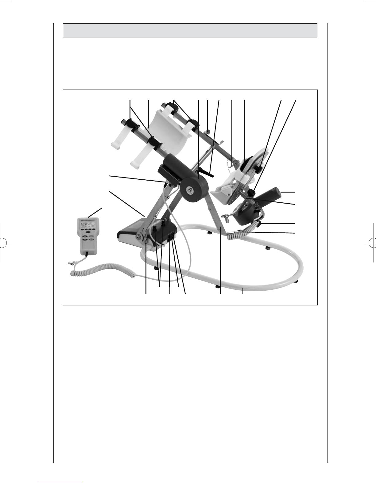
Device description
2

A
C
E
B
D
F
G H
KINEX-Ankle setup illustrations
3

Contents
Description of the KINEX-Ankle System 2
KINEX-Ankle setup illustrations 3
Symbol overview 35
1. How to use the CPM device 5
1.1 Fields of application 5
1.2 Therapy objectives 5
1.3 Indications 5
1.4 Contraindications 5
2. Description of the KINEX-Ankle 6
2.1 Description of the device components 6
2.2 Description of the programming unit 7
2.3 Explanation of symbols 10
2.4 Explanation of symbols (connections and nameplate) 11
3. Safety information 12
4. Device setup 15
4.1 Connecting the device, performance check 15
4.2 Adjusting the device to the patient 16
5. Setting the treatment values 17
5.1 General information on programming KINEX-Ankle 17
5.2 Programming KINEX-Ankle 18
5.3 Treatment value details 19
6. Care, Maintenance, Transport, Conversion 26
6.1 Care 26
6.2 Maintenance (fuse replacement) 26
6.3 Transport 27
6.4 Conversion 28
7. Environmental Protection Statement 29
8. Specifications 29
9. IEC 60601-1-2:2001 30
9.1 Electromagnetic emissions 30
9.2 Electromagnetic immunity 31
9.3 Recommended Separation Distances 33
10. Contact 33
11. Technical service 34
11.1 Technical Hotline 34
11.2 Shipment 34
11.3 Spare Parts 34
4
1. How to use the CPM device
The CPM device is indicated in the
treatment of most injuries and diseases
of the ankle joint as well as in the postoperative treatment after joint surgery
and in the treatment of joint diseases.
Examples:
- joint distortion and contusion
- arthrotomy and arthroscopy procedures in combination with synovectomy,
arthrolysis or other intra-articular interventions
- mobilization of joints in anesthetized
patients
- exercise-stable fractures after surgery, pseudoarthrosis and osteotomy
- myoplasty
- arthroplasties including implantation
of endoprostheses
Do NOT use KINEX-Ankle on
patients with:
- acute inflammatory processes in the
joints, unless on the order of a physician
- spastic paralysis
- unstable osteosynthesis
1.3 Indications
1.4 Contraindications
KINEX-Ankle is a motor-operated Con-
tinuous Passive Motion (CPM) device
providing motion to the ankle joint.
Suitable for use in hospitals, clinics, general practices and rental services, it is
an important supplement to medical
and therapeutic treatment.
CPM therapy with KINEX-Ankle is
mainly used to prevent the negative effects of immobilization, to allow patients
to regain painless mobility of joints at an
early stage and to promote healing and
achieve a positive functional result.
Other objectives of therapy include:
- improvement of joint metabolism
- prevention of joint stiffness
- promotion of the regeneration and healing of cartilage and damaged ligaments
- faster hematoma/fluid resorption
- improved lymph and blood circulation
- thrombosis and embolism prophylaxis
1.1 Fields of application
1.2 Therapy objectives
5
2. Description of the KINEX-Ankle
Note: See also page 2!
1. Clamping levers to adjust the height
of the calf support assembly
2. Calf support assembly
3. Motor A (center of rotation for dorsal extension/plantar flexion)
4. Bracket for programming unit
5. Clamping lever to adjust the inclination of the carriage
6. Aiming pin for adjustment of the rotational axis of the upper ankle joint
7. Footplate
8. Knurled screw for adjustment of the
footplate height
9. Knurled screw to adjust the footplate to the leg length
10. Motor B
11. Footplate bracket
12. Thumbscrew to secure motor B on
the moving bracket for dorsal extension / plantar flexion
13. Bore hole to mount motor B to the
moving bracket for dorsal extension/
plantar flexion
14. CPM base
15. Moving bracket for dorsal extension/
plantar flexion
16. Power switch (ON/OFF)
17. Fuse cap
18. Connection for power cord
19. Locking device to adjust the height
of the carriage
20. Perforation to set the height of the
carriage
21. Programming unit
22. Nameplate
23. Connection for programming unit
2.1 Description of the
device components
The motorized CPM device provides the
following passive motion to the ankle
joint:
plantar flexion / dorsal extension
50° / 0° / 40°
inversion / eversion
40° / 0° / 20°
It can be reconfigured for use on either
side and allows patients to exercise in
bed and while sitting on a chair.
Note!
To unambiguously represent the current position of the CPM device, the
values for plantar flexion and inversion are marked with the symbol "-"
both on the display and in this document.
These are some of the
KINEX-Ankle features:
- anatomically correct setup
- physiological movements
- programming unit for precise
adjustment of patient-specific
therapy values
- symbols for easy operation of the
programming unit
Biocompatibility
Those parts of the KINEX-Ankle device
that come into contact with the patient
when the device is used as intended,
are designed to fulfil the biocompatibility requirements of the applicable standards.
6
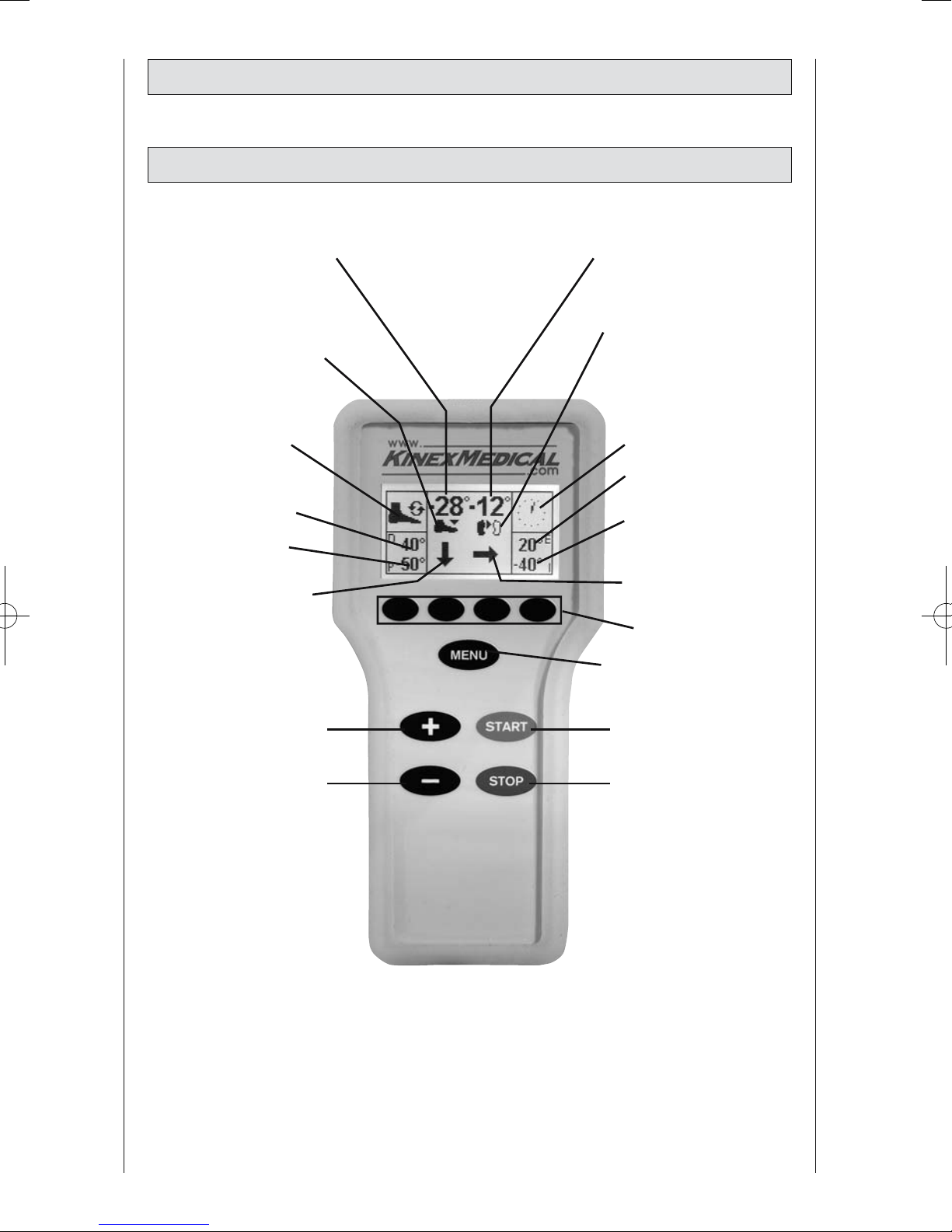
2.2 Description of the programming unit
2.2.1 Programming unit in normal mode
set angle of motor A
current position of motor A
(arrow pointing up =
dorsal extension
arrow pointing down =
plantar flexion)
set
dorsal extension value
set
plantar flexion value
motor A - selected
direction of motion
set angle of motor B
current position of motor B
(left or right - solid foot
symbol /
arrow pointing inward =
inversion
arrow pointing outward =
eversion)
therapy timer
set eversion value
set inversion value
motor B - selected
direction of motion
parameter keys
MENU key
START key“+” key
“-” key STOPkey
selected therapy
protocol
7
8
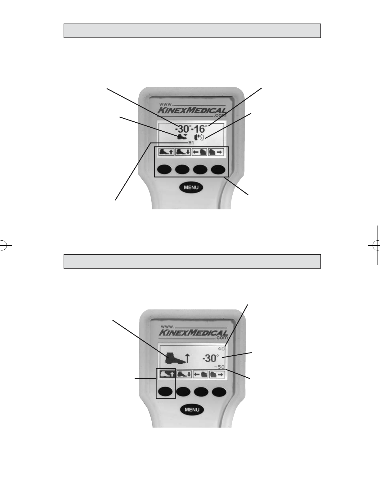
2.2.2 Programming unit in MENU selection mode
2.2.3 Programming unit set to ROM programming
set carriage angle for
dorsal extension /
plantar flexion
current position of
motor A
(arrow pointing up =
dorsal extension
arrow pointing down
= plantar flexion)
selected MENU level
selected function
current maximum dorsal
extension value
current maximum plantar
flexion value
set carriage angle
selected parameter
(here: dorsal extension)
set carriage angle for
inversion / eversion
current position of
motor B
(left or right - solid foot
symbol /
arrow pointing inward =
inversion
arrow pointing outward
= eversion)
parameters available for
selection and corresponding parameter keys
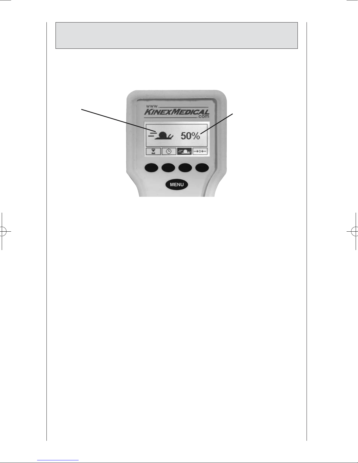
selected function status of the selected
function (here: speed)
9
2.2.4 Programming unit in general programming
mode
10
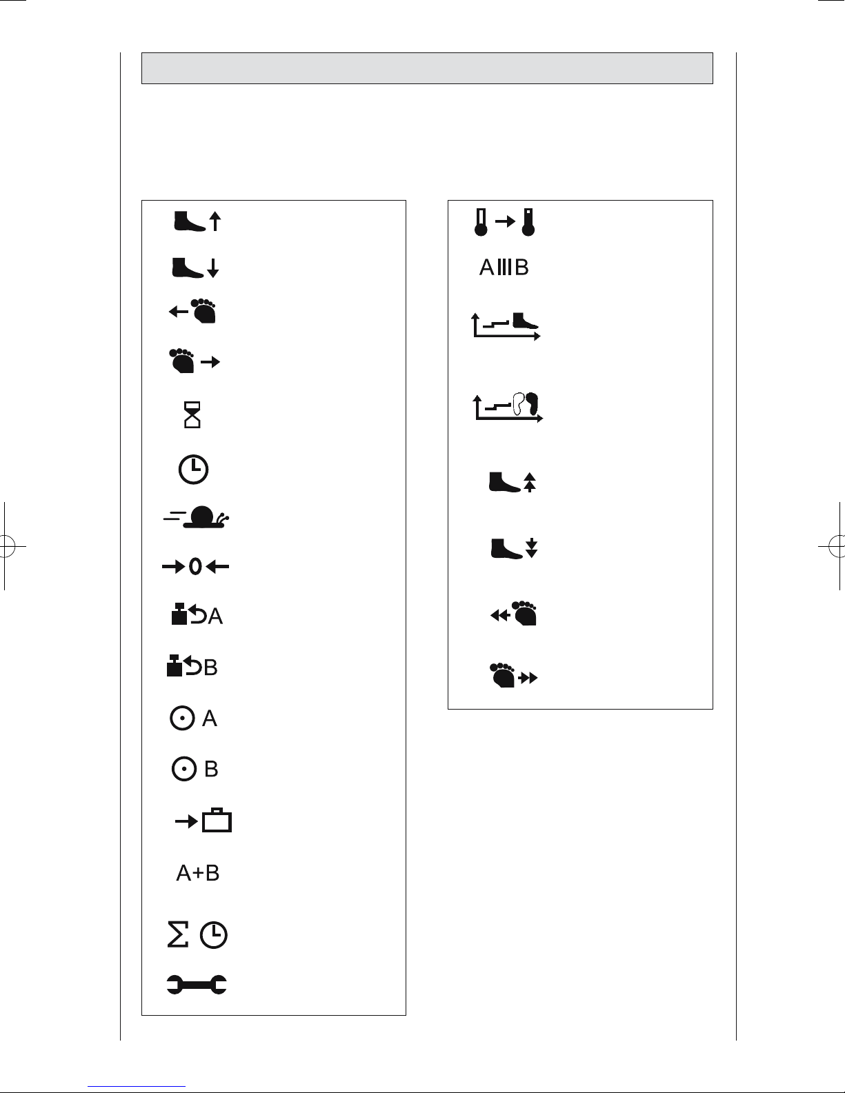
2.3 Explanation of symbols
Also refer to symbol overview on page 36
dorsal extension
plantar flexion
inversion
eversion
pause
timer
speed
new patient
load reversal
motor A
load reversal
motor B
motor A ON/OFF
motor B ON/OFF
transport setting
synchronized/nonsynchronized mode
total therapy time
service menu
warm up protocol
isolation protocol
dorsal extension /
plantar flexion therapy
documentation
inversion /
eversion therapy
documentation
stretching in
dorsal extension
stretching in
plantar flexion
stretching in
inversion
stretching in
eversion
11
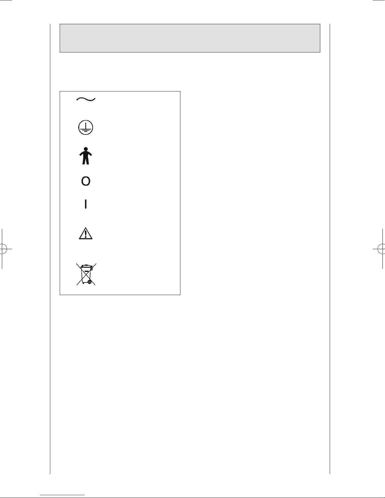
2.4 Explanation of symbols
(connections and nameplate)
alternating current
protective earth
connection
type B applied part
power switch OFF
power switch ON
Refer to accompanying
documents
Do not dispose of
product with unsorted
household or municipal
waste.
 Loading...