

Page 1
KINETEC CEM™
Manuel d'utilisation
Avant toute utilisation lire ce document.
Kinetec se réserve le droit de toutes modifications techniques.
FR
User manual
Before use, please read this document.
Kinetec reserves the right to effect technical modifications.
EN
Bedienungsanleitung
Vor Benutzung unbedingt dieses Dokument lesen.
Kinetec behält sich das Recht vor, jegliche technische Änderung
durchzuführen.
DE
467896366 – 12/2014
Série 1-2
Notice Originale
Page 2

KINETEC CEM™ 1/22 EN
Contents
Page
DESCRIPTION .................................................................................................................................................................................................... 2
1. Definition ........................................................................................................................................................................................... 2
2. Indications ........................................................................................................................................................................................ 2
3. Clinical Benefits ................................................................................................................................................................................ 2
4. Contraindications .............................................................................................................................................................................. 2
5. Warning and safety instructions ....................................................................................................................................................... 3
6. Compliance: ...................................................................................................................................................................................... 3
7. Unpacking and packing .................................................................................................................................................................... 4
8. Installing the device .......................................................................................................................................................................... 4
9. Basic assembly ................................................................................................................................................................................. 5
10. Assembling the components of the KINETEC CEM™ ..................................................................................................................... 5
11. Transporting the device .................................................................................................................................................................... 6
12. Description ........................................................................................................................................................................................ 6
USING THE HAND CONTROL............................................................................................................................................................................ 8
1. Electrical connection: safety first ...................................................................................................................................................... 8
2. Starting the unit ................................................................................................................................................................................ 8
3. Changing the display language ........................................................................................................................................................ 9
4. Locking-Unlocking the hand control setting ...................................................................................................................................... 9
5. START/STOP/REVERSE function ................................................................................................................................................... 9
6. Procedure to stop the machine ......................................................................................................................................................... 9
7. Session Time .................................................................................................................................................................................. 10
8. Quick Start ...................................................................................................................................................................................... 10
9. Possible values for each parameter ............................................................................................................................................... 10
10. To set the parameters for a single movement ................................................................................................................................ 11
11. PROGRAM MODE: To enter a program ........................................................................................................................................ 12
12. Using Programs .............................................................................................................................................................................. 14
13. Reading the values of a program: e.g. SPEED .............................................................................................................................. 14
14. To use the WARM UP key .............................................................................................................................................................. 15
15. To define the patient tolerance • At the start of a session .............................................................................................................. 16
16. To define the patient tolerance • During the session ...................................................................................................................... 16
17. Session Time .................................................................................................................................................................................. 16
USING THE KINETEC PATIENT PAD KIT........................................................................................................................................................ 17
SETTING UP THE PATIENT ............................................................................................................................................................................. 18
PRODUCT INFORMATION ............................................................................................................................................................................... 19
1. Maintenance ................................................................................................................................................................................... 19
2. Trouble shooting ............................................................................................................................................................................. 19
3. Cleaning ......................................................................................................................................................................................... 19
4. Disposal and recycling .................................................................................................................................................................... 19
5. Technical specifications .................................................................................................................................................................. 20
6. Symbols used ................................................................................................................................................................................. 20
7. Warranty ......................................................................................................................................................................................... 20
8. Guidance and manufacturer’s declaration ...................................................................................................................................... 21
Page 3

KINETEC CEM™ 2/22 EN
DESCRIPTION
1. Definition
The device KINETEC CEM™ is a PASSIVE mobilisation device allowing Extension/Flexion
movements of the ELBOW from -10° to 135° with fixed prono-supination, in all abduction planes of
the shoulder.
It is available as a complete device with chair or as an add-on module that can be used on Series 2
or higher KINETEC CENTURA™ devices.
2. Indications
- Intra-articular fractures of the elbow
- Metaphyseal fractures, osteosynthesised in the elbow area
- Arthrolysis for post-traumatic stiffness with limitation of elbow movement
- Elbow prostheses
- Synovectomies
3. Clinical Benefits
- Effectively breaks the vicious circle of: trauma immobility effusion atrophy.
- Improves the nutrition of joint surfaces.
- Speeds the recovery of post-operative range of motion.
- Speedy recovery of the motor pattern for the limb operated on.
- Promotes joint cartilage healing.
- Provides immediate post-operative continuous passive motion.
- Reduces hospitalization time.
- Reduces the need for pain medication.
- Visual feedback for users.
- Realization of postures (resting, stretching muscles).
4. Contraindications
Rheumatoid arthritis in the inflammatory phase, algodystrophy in the inflammatory phase (hyper
painful), para-osteo-arthroplasty, unhealed infected wounds, bone cancer, infectious arthritis,
deformed joint surfaces, paralysed limbs (atonic or spastic), non-stabilised fractures.
Page 4

KINETEC CEM™ 3/22 EN
DESCRIPTION
5. Warning and safety instructions
WARNING: The machine must be installed and commissioned according to the information provided in this
manual.
WARNING: If you need any assistance in the assembly, use or maintenance of the device, please contact
your KINETEC
®
distributor.
WARNING: The practitioner determines the protocol and ensures its proper implementation (settings, session
duration and frequency of use).
WARNING: Run a cycle with the device unloaded before installing the patient on the machine.
WARNING: For optimum safety, always give the hand control to the patient before starting the system. The
patient must know the start/stop/reverse function on the hand control (see page 9).
WARNING: To avoid the parameters being changed, lock the machine’s hand control before giving it to the
patient.
WARNING: Danger, risk of explosion: Do not use the machine with anaesthetic gas or in an environment that
is rich in oxygen.
WARNING: For Type B Class I devices, and to avoid all risks of electric shock, the machine should only be
connected to a power supply that has protective earthing, see page 8.
WARNING: Before using this machine, always check that the electrical socket is in good condition and is
suitable for the splint power supply cord. Only use the original cable supplied with the machine.
Check that the cables remain free around the device so that they do not get damaged.
WARNING: Before using this machine, always check that the machine is not damaged, in particular the
protective housings.
WARNING: In case of electromagnetic interference with other devices move the device.
WARNING: Please do not touch the fixed or moving parts while the unit is running: pinching or crushing risk.
Keep children and pets away from the machine.
WARNING: Modifying the machine in any way is strictly forbidden.
WARNING: Always check the motion parameters displayed on the hand control before starting the device.
WARNING: Only the accessories, spare parts and supplies described in this manual should be used with this
machine.
WARNING: Do not connect the device to other devices not described in this manual.
WARNING: If unforeseen events or malfunctions occur, please contact your KINETEC
®
distributor.
WARNING: Before each use, always check that the red knobs under the chair have been tightened (see page
5).
WARNING: Before each use, always check that the various locking knobs have been tightened (see pages 6
and 7).
WARNING: Wireless communications devices, such as domestic wireless devices in networks, mobile
phones, wireless telephones and their base stations and walkie-talkies, may affect the machine.
You are recommended to keep at least a distance d between these devices and the machine.
See the table on page 22.
6. Compliance:
The device KINETEC CEM™ meets the requirements of the Medical Directive No. 93/42/EEC. It bears the EC mark.
The device KINETEC CEM™ complies with the standards in force: IEC 601601-1-2 concerning the electromagnetic compatibility of
medical devices and IEC 60601-1 concerning electrical safety.
The device KINETEC CEM™ meets the requirements of the Machinery Directive No. 2006/42/EC.
Page 5
KINETEC CEM™
4/22
EN
DESCRIPTION
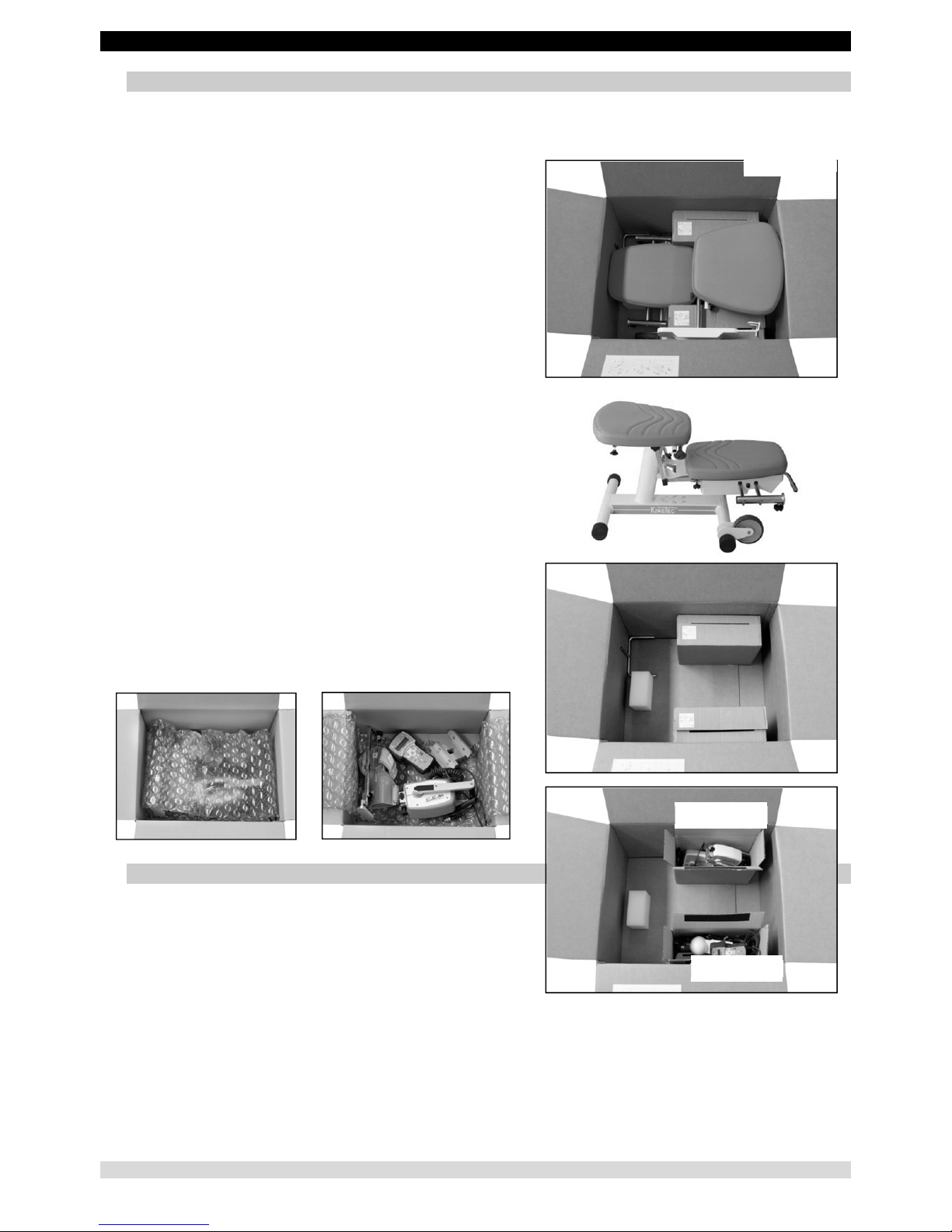
7. Unpacking and packing
Unpacking
When you unpack the machine, don't forget that you may need to pack it up again. We recommend that you keep the packaging
materials, boxes and plastic bags.
Your KINETEC CEM™ device is delivered in two boxes
- Box 1: Centura device (including the chair)
- Box 2: Accessories specific to the KINETEC CEM™ device
Recommendations for plastic bags: do not put them over
the head as there is a risk of suffocation, and keep them out
of the reach of children.
Be careful with small-sized pieces: they could be swallowed
by a child.
Be careful with cables and wires: risk of strangulation.
Packing
To prevent any problems when the machine is transported, only pack
it using its original packaging.
- Remove all accessories from the machine.
Box 1:
- Fold the machine into the transport position (see page 5).
- Pack each element in a plastic bag.
- Put the elements in the two boxes; do not place anything between
the boxes.
• Box A – the motor units
• Box B – the other accessories, except for the arm rest
- Place the machine in its box.
Box 2:
- Put the accessories specific to the KINETEC CEM™ in this box.
8. Installing the device
The device KINETEC CEM™ machine is designed to be used in
hospitals, clinics, doctors' offices or in private homes (rental).
The machine is delivered with its own chair. It must not be used
with another chair.
The machine must be installed on a flat surface that is wide
enough to accommodate the entire device; you should leave a
free space of 1 m (39 ins.) on each side.
Box A
Box B
Box 1
Page 6
KINETEC CEM™
5/22
EN
1
2
4
4
3
5
DESCRIPTION
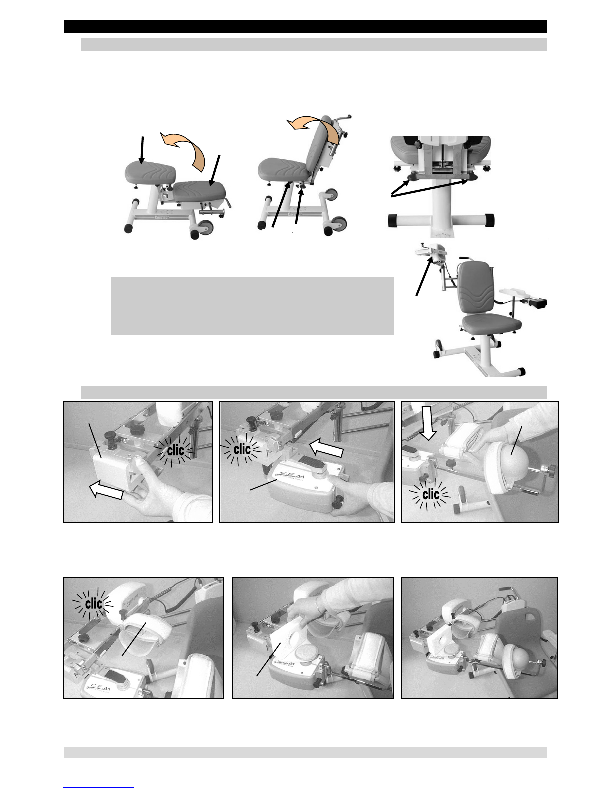
9. Basic assembly
- Place the chair (1) on the floor; we recommend that two people carry out this operation.
Take care not to trap your fingers.
- Straighten up the back of the chair (2).
The tilting axis (3) must always be in good condition. Never use the device without it.
- Lock the back of the chair by tightening the red knobs (4).
- Install the abduction motor (5) on the right or left, depending on
the limb be moved.
WARNING: Before each use, always check that the red knobs
under the chair have been tightened (see page 5).
WARNING: Before each use, always check that the various
locking knobs have been tightened (see pages 6
and 7).
Comments and special instructions:
Take care that fingers do not get pinched during handling operations or
when the chair is unfolded.
Never carry the device by the chair when it is in its working position.
10. Assembling the components of the KINETEC CEM™ Kit
Install the elbow motor support (3) Install the elbow motor (2) Install the forearm splint (6).
using the colour code as guide using the colour code as guide. It is correctly installed when you hear a click.
(Blue for left, Red for right). It is correctly installed when you hear a click.
It is correctly installed when you hear a click.
Install the arm splint (5). Install the elbow protection (4). The device KINETEC CEM™ is shown ready
It is correctly installed when you hear a click. for a right shoulder mobilisation.
3
2
6
5
4
Page 7
KINETEC CEM™
6/22
EN
4
3
9
8
10
9
11
13
12
DESCRIPTION
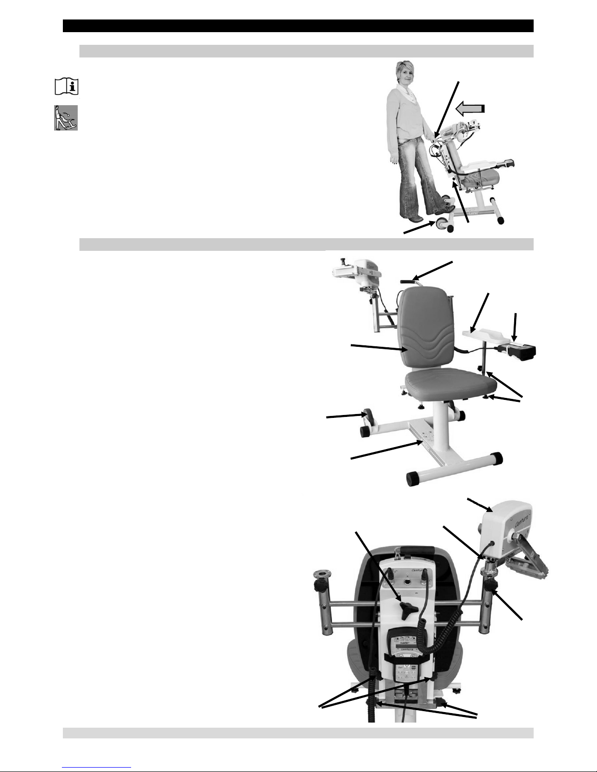
11. Transporting the device
For easy transport of the unit, the chair has two wheels (3) and a handle
(4).
Place the arm support as close as possible to the chair to limit the overall
dimensions and help balance the unit.
Place your foot as indicated to tilt the unit.
You can adjust the height of the handle with the knobs (9).
12. Description
The device KINETEC CEM™ consists of the following
components:
1 – Chair
2 – Base
3 – Wheels
4 – Handle
5 – Arm rest knobs
6 – Arm rest
7 – Hand control support
8 – Right/left sliding motor mount bar locking knob
9 – Up/down sliding housing locking knob
10 – Chair locking knob
11 – Abduction motor locking knob
12 – Abduction motor
13 – Shoulder depth sliding lock
1
2
3
4
5
6
7
Page 8
KINETEC CEM™ 7/22 EN
DESCRIPTION
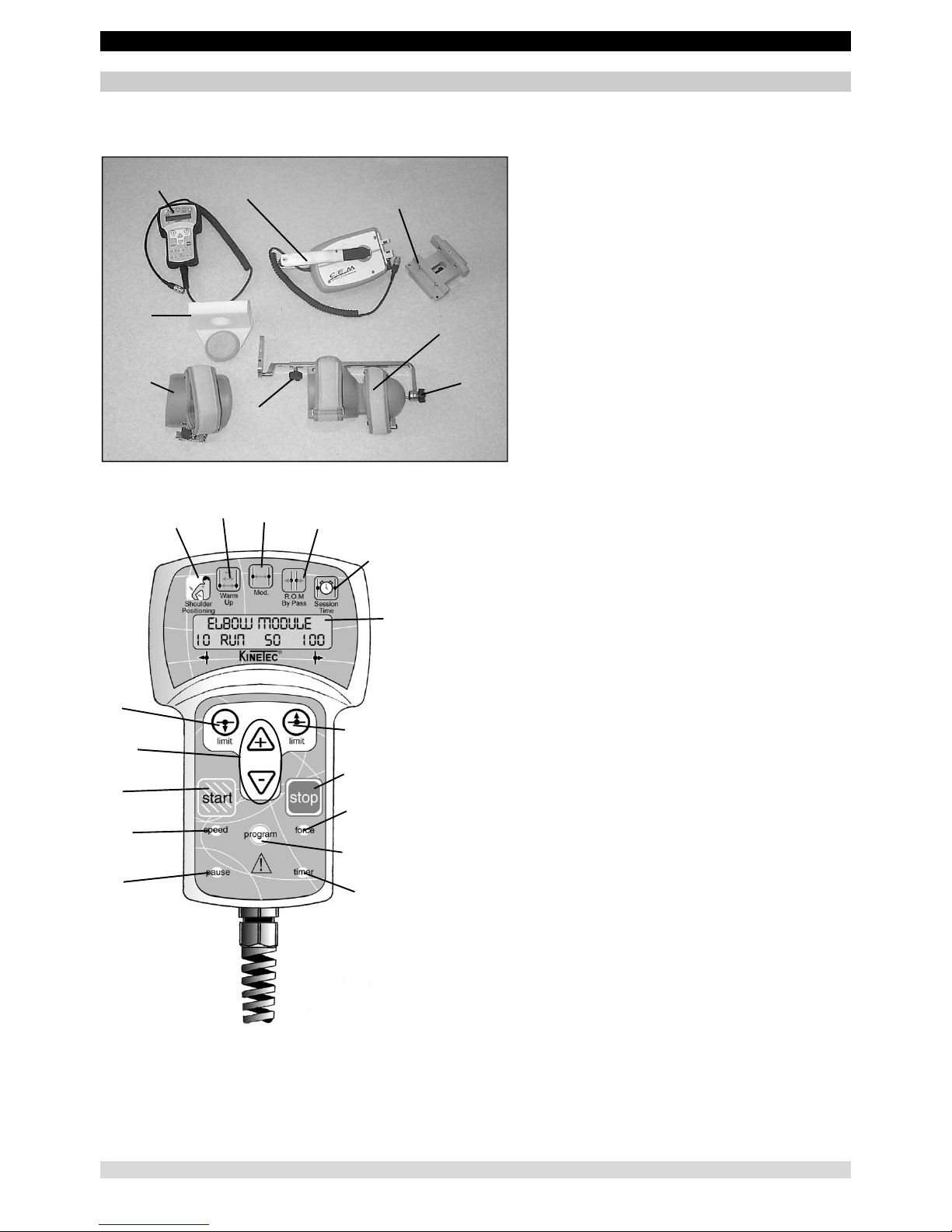
Description
Composition of the KINETEC CEM™ Module:
1 • Hand control
2 • Extension – Flexion motor
3 • Elbow motor support
4 • Elbow protection
5 • Arm splint
6 • Forearm splint
7 • Forearm length setting lock
8 • Prono-Supination position setting lock
9 • Liquid-crystal display (2 lines of 16 characters)
10 • SESSION TIME display key
11 • BYPASS mode key
12 • MODULATION key
13 • WARM UP key
14 • Shoulder positioning key
15 • Upper limits setting
16 • Lower limits setting
17 • Increase / decrease keys
18 • START key
19 • STOP key
20 • FORCE key
21 • SPEED key
22 • PAUSE key
23 • TIMER key
24 • PROGRAM access key
1
4
2
3
6
85
7
9
10
11
12
13
14
16
17
18
21
22
23
24
20
19
15
Page 9

KINETEC CEM™
8/22
EN
1
2
3
USING THE HAND CONTROL
1. Electrical connection: safety first
2 versions of electrical protection are available for KINETEC CEM™ machines.
The identification label shows which version a machine is equipped with:
Type BF, Class II devices,
for home use, bear the following symbols:
Type B class I devices,
for use in a professional environment, bear the following symbol:
See page 20 for the meaning of the symbols.
Before connecting the device to the power supply, check that the mains voltage
matches that shown on the plate (100-240 V~ 50/60Hz).
The connectors can be plugged in any one of the sockets
(the sockets are not assigned to a specific connector).
Connect the power supply cable (1).
IMPORTANT
For Type B Class I devices, and to avoid all risks of electric shock, the
machine should only be connected to a power supply that has protective
earthing.
To connect the power supply, only use the original cable supplied with the machine.
Check that the cables remain free around the device so that they do not get damaged.
Check that the machine is not damaged, in particular the protective housings.
Watch out for the position of the motor cables. They must remain clear around the machine.
Wrong position Correct position
2. Starting the unit
Press the ON / OFF switch (2). The indicator light (3) lights up, the machine carries out an auto-diagnostic, and then the
display shows:
KINETEC
ELBOW MODULE
Then
Movement Verif.
Please Wait
Then
ELBOW MODULE
30 STOP 15 70
Your device KINETEC CEM™ is ready to be used with the parameters from the previous session
(except Timer and Warm Up mode)
Warning: Always check the motion parameters displayed on the hand control before starting the session.
Page 10

KINETEC CEM™
9/22
EN
4
USING THE HAND CONTROL
3. Changing the display language
Press the SPEED and FORCE buttons simultaneously,
then press the + or - key to change the display language.
Press to confirm, then switch the unit OFF and then ON again
to apply the changed display language.
Available languages: English, French, German, Italian and Spanish.
4. Locking-Unlocking the hand control setting
The hand control allows the patient to control the machine as
appropriate.
The switch (4) has 3 positions:
Fully locked position
In this mode the only functions available are reading the operational settings
and using the START/STOP function.
Fully unlocked position
All the operational settings can
be changed.
Half-locked position
In this mode, it is possible to switch the program and modify the upper and lower movement limits. The
START/STOP function is always accessible.
Double locking
Simultaneously press the + and - keys to lock the hand control.
The display shows "LOCK". To unlock the hand control, simultaneously press
the + and - keys; the display reads "UNLOCK".
You cannot change the parameters; if you try, the message "LOCK" will be displayed.
We recommend that you lock the hand control when you
give it to the patient.
Note: the hand control locking is preserved when you switch the unit ON/OFF.
5. START/STOP/REVERSE function
As with all KINETEC® systems, the device KINETEC CEM™ is equipped with a START/STOP/REVERSE
function.
Press this key of the hand control and the movement stops.
Press this key of the hand control and the movement starts in the opposite direction.
IMPORTANT: for optimum safety, always give the hand control
to the patient before starting the system.
6. Procedure to stop the machine
To stop the machine's movement: press the STOP key
To switch power off: press the ON / OFF switch (see page 8)
Page 11

KINETEC CEM™
10/22
EN
USING THE HAND CONTROL
7. Session Time
This function allows you to see how long the unit has been operating since it was last reset.
Beginning
Keys to
press
Display Remarks
To stop the unit
FLEX/EXT
50 STOP 15 100
Check whether the hand
control is in the position
or
Press simultaneously on the 2 keys
TOTAL TIME 0125H
RESET: low.limit
The display shows how long
the unit has been operating
since it was last reset.
To reset the counter, press the key
TOTAL TIME 125H
Reset to zero
This message disappears after a
few seconds; the counter is now
reset.
Or
After 5 seconds the time is no
longer displayed, but it remains in
the memory.
FLEX/EXT
50 STOP 15 100
8. Quick Start
Set up the patient and proceed as below:
Beginning
Keys to
press
Display Remarks
Switch the unit ON
KINETEC
ELBOW MODULE
Movement Verif.
Please Wait
Movement Verif.
Motor: M1 M2
ELBOW MODULE
0 STOP 80 135
The last movement used is displayed
To start the session with the parameters
from the previous session.
ELBOW MODULE
0 RUN 10 135
The angle display changes with the current
movement.
Note: the values in the display column are given as an example. In actual use, they will come from stored
programs or previous sessions.
9. Possible values for each parameter
Possible values Default setting
• Treatment mode Normal
• Shoulder positioning 60° to 90° -
• Extension limit -10 to 130° -10°
• Flexion limit -5° to 135° 135°
• Speed
1 to 5 (from 50° to 145° per minute)
2
• Force
1 to 6
6
• Extension pause 0 to 900 seconds (15 minutes) 0
• Flexion pause 0 to 900 seconds (15 minutes) 0
• Timer No timer (00H00) to 24H00 0
Page 12

KINETEC CEM™
11/22
EN
USING THE HAND CONTROL
10. To set the parameters for a single movement
Beginning
Keys to
press
Display Remarks
To stop the unit
ELBOW MODULE
25 STOP 85 135
Check that the hand control is not
locked (See page 9).
To display the extension or flexion limit of
the movement
ELBOW MODULE
25 EXT 85 135
The value blinks.
ELBOW MODULE
40 FLEX 85 135
To change the limit if necessary
or
ELBOW MODULE
40 FLEX 85 60
The new value blinks.
To confirm the new value, press another
key
or wait more than 3 seconds for automatic
confirmation.
ELBOW MODULE
SPEED 2
While the value blinks press
the or key
to change if necessary.
ELBOW MODULE
FORCE _ _ _ _ _
ELBOW MODULE
TIMER 00H00MIN
Or
To display the pause at the extension or
flexion limit
ELBOW MODULE
PAUSE LOW 0s
Successive presses on this key
selects the pause at the extension
or flexion limit.
ELBOW MODULE
PAUSE HIGH 0s
To change the pause if necessary
or
ELBOW MODULE
PAUSE HIGH 15s
The new pause value blinks.
To confirm the new value press another key
or wait more than 3 seconds. The display
shows the selected mode
ELBOW MODULE
40 STOP 85 60
The unit is ready to start with the
new parameters.
Comments:
• The values in the display column are given as an example.
Page 13

KINETEC CEM™
12/22
EN
USING THE HAND CONTROL
11. PROGRAM MODE: To enter a program
Beginning
Keys to
press
Display Remarks
To switch off the unit
Press the 2 keys at the same time and
switch the unit ON
KINETEC
ELBOW MODULE 0.6
Welcome text displayed for 3
seconds
Then
PROGRAM Nr2
EMPTY
The program number blinks.
To change the program if necessary
or
PROGRAM Nr10
EMPTY
The new program number blinks.
To choose the treatment mode
PROGRAM Nr10
10 EXT/FLEX 90
The display indicates the selected
treatment mode, the program
number blinks again.
Or
PROGRAM Nr10
10 WARM UP 90
To display the extension or flexion limit of
the movement
PROGRAM Nr10
10 EXT/FLEX 90
The value blinks.
Or
PROGRAM Nr10
20 EXT/FLEX 120
To change the limit if necessary
or
PROGRAM Nr10
20 EXT/FLEX 120
The new value blinks.
To confirm the new value, press another
key
or wait more than 3 seconds
PROGRAM Nr10
SPEED: 1
While the value blinks press
or
to change if necessary.
PROGRAM Nr10
FORCE: _ _ _ _ _
PROGRAM Nr10
TIMER 00H00MIN
PROGRAM Nr10
PAUSE LOW 0s
To record program 10
PROGRAM Nr10
SAVE:+ CLEAR:-
Then
PROGRAM Nr10
SAVING
Program 10 has been recorded and
the display indicates the next
program so you can change
another program.
OR
To cancel the program
PROGRAM Nr10
CLEARING
Program 10 has been removed and
the display indicates the next
program so you can change
another program.
To exit program mode, switch the unit OFF
and switch back ON.
KINETEC
ELBOW MODULE 0.6
To use the modified program see
page 14.
Comments:
• The values in the display column are given as an example.
Page 14

KINETEC CEM™ 13/22 EN
USING THE HAND CONTROL
PROGRAM MODE: To enter a program
Comments:
• When a program has been deleted, the display shows PROGRAM NR11
EMPTY
Program table:
Timer
Pause at lower
limit
Pause at upper
limit
Force
Speed
Upper limit
Lower
limit
Movement type
• Program
number
1
2
3
4
5
6
7
8
9
10
11
12
13
14
15
16
Page 15

KINETEC CEM™
14/22
EN
USING THE HAND CONTROL
12. Using Programs
The device KINETEC CEM™ allows you to store up to 16 programs (numbered 1 to 16), including the type of movement,
ROM, speed, load, pauses and timer.
The original parameter values of the program are empty. These values can be modified and saved at any time (see ‘To
enter a program’, page 12)
Beginning
Keys to
press
Display Remarks
To stop the unit
ELBOW MODULE
10 STOP 0 110
Check that the hand control is not locked
(See page 9).
To access program mode
PROGRAM Nr10
20 EXT/FLEX 90
The program number blinks.
To change the program if necessary
or
PROGRAM Nr3
5 WARM UP 135
The new program number blinks.
To exit and confirm the selected program
WARM UP
5 STOP 0 135
The current parameters are those recorded
in program 3.
To exit without confirming the selected program
ELBOW MODULE
10 STOP 0 110
Back to the starting parameters.
To start the unit
WARM UP
5 STOP 37 135
The angle display changes with the current
movement.
13. Reading the values of a program: e.g. SPEED
Beginning
Keys to
press
Display Remarks
To stop the unit
ELBOW MODULE
10 STOP 0 110
Check that the hand control is not locked
(See page 9).
To access program mode
PROGRAM Nr3
5 WARM UP 135
The program number blinks.
To change the program if necessary
or
PROGRAM Nr10
20 EXT/FLEX 90
The new program number blinks.
To read the speed value
PROGRAM Nr10
SPEED: 2
Displays the speed value.
After 5 seconds or after pressing on another key
ELBOW MODULE
10 STOP 0 110
To exit and confirm the selected program
ELBOW MODULE
20 STOP 0 90
The current parameters are those recorded
in program 3.
To start the unit
ELBOW MODULE
20 RUN 35 90
The angle display changes with the current
movement.
Comments:
• The values in the display column are given as an example. They actually depend on the stored programs.
• The current movement parameters can be changed while using that program but no data will be stored in the original
program. See programming mode (page 12) to modify programs.
Page 16

KINETEC CEM™
15/22
EN
USING THE HAND CONTROL
14. To use the WARM UP key
Beginning
Keys to
press
Display Remarks
To stop the unit
ELBOW MODULE
20 STOP 15 90
Check that the hand control
is not locked (See page 9).
To select Warm Up mode
WARM UP
20 STOP 15 90
To start the movement
WARM UP
20 RUN 15 90
The angle display changes
with the current movement.
Warm Up rules.
The device KINETEC CEM™ starts at 70% of the full ROM, increasing 5% of the range each full cycle until the pre-set ROM is
reached.
Note:
- The parameters should only be modified while the unit is stopped.
- Pauses and ByPass mode are not available during warm up cycles.
- The Warm Up cycles are only performed when the movement is first started.
- To start a new Warm Up session, press the "Warm Up" key twice.
- The calculation mode used enables the pre-set ROM to be reached in approximately seven full cycles.
Example:
For a Warm Up treatment with a pre-set ROM from 0° to 100°.
The first cycle starts with 15° to 85° to 15° and the values increase 5% each cycle.
100°
0°
50°
Cycle 1 (70%)
Cycle 2 (75%)
Cycle 3 (80%)
Cycle 4 (85%)
Cycle 5 (90%)
Cycle 6 (95%)
Cycle 7 (100%)
Amplitud es de mou vement progr ammées
Page 17

KINETEC CEM™ 16/22 EN
USING THE HAND CONTROL
15. To define the patient tolerance • At the start of a session
This function, MODULATION Mode, allows the maximum limits that a patient can tolerate to be defined and recorded at the
beginning of a session.
Set up the patient and proceed as below:
Beginning
Keys to
press
Display Remarks
Switch the unit ON
ELBOW MODULE
20 STOP 25 90
If Warm Up mode is selected, switch OFF
this mode by pressing the "Warm Up" key.
To select
MODULATION Mode
MODUL. : use + or -
20 STOP 25 90
The display indicates the keys used to run
the machine. This message is displayed 3
seconds.
To select the pain level
(+ key for flexion, - key for extension)
OR
continuously press
MODUL. : use + or -
20 MANUAL 37 90
The unit begins to move as selected.
The settings are controlled by you.
To set the pain level when reached, press
OR
MODUL. : use + or -
37 MANUAL 37 102
The new limit of the movement is recorded.
To start the session with the new movement limits
ELBOW MODULE
37 RUN 37 90
The angle display changes with the current
movement.
Note: when the movement's max. limit (-10° or 135°) is reached, the max. angle is automatically recorded and the function is exited.
16. To define the patient tolerance • During the session
This function, BYPASS Mode, allows the maximum limits that a patient can tolerate to be defined and recorded, which
allows you to work on increasing amplitude.
IMPORTANT: Can be used only when the machine is running.
Beginning
Keys to
press
Display Remarks
The unit is running
ELBOW MODULE
37 RUN 37 90
Check that the hand control is not locked
(See page 9).
To select
BYPASS Mode
BYPASS: use + or -
37 RUN 37 90
The display indicates the keys used to run
the machine. This message is displayed 3
seconds.
To select the NEW pain level
OR
continuously press
BYPASS: use + or -
-5 BYPASS -5 90
The unit begins to move as selected.
The settings are controlled by you.
To set the new pain level when reached, press
OR
BYPASS: use + or -
-5 BYPASS 10 70
The new limit of the movement is recorded.
Continue the session with the new movement limits
ELBOW MODULE
-5 RUN 57 70
The angle display changes with the current
movement.
Note: This function is only available during the warm-up cycles in Warm Up mode.
When the movement's max. limit (-10° or 135°) is reached, the max. angle is automatically recorded and the function is
exited.
17. Session Time
This function shows the running time (in minutes) of the session (motor functioning).
• It is directly accessible by the key , the display shows TIME 02h25
This counter is reset each time the unit is switched ON.
Page 18

KINETEC CEM™ 17/22 EN
USING THE KINETEC PATIENT PAD KIT
The device KINETEC CEM™ is delivered with 3 straps:
• 1 - Arm strap (A)
• 2 - Forearm straps (B)
• 1 - Elbow protection (C)
All these straps are used the same way (see
pictures).
Do not tighten the straps too much.
FOR OPTIMAL HYGIENE,
A NEW SET OF PADS SHOULD BE USED FOR EACH PATIENT.
Recommendations to obtain maximum hygiene for the straps:
• Sterilizing the straps (if necessary): Sterilize at 134 °C for 18 minutes.
• Disinfecting the straps:
Wash at 30°C, using a disinfectant solution during the rinse cycle.
Example of product which can be used: Solution "Baclinge" at 0.125 % or "Souplanios" at 0.125% from
ANIOS Laboratory. A complete list of distributors in your country is available on request.
A
B
C
B
Page 19

KINETEC CEM™
18/22
EN
SETTING UP THE PATIENT
Make sure the straps are clean.
Put the unit in the position that is the most comfortable for the patient.
Setting the position of the shoulder axis
Press the key.
Then continuously press
The motor operates, allowing a shoulder position
between 60° and 90° of abduction.
If neither key is pressed for 3 seconds, this
function stops.
The knob (29) allows you to adjust the abduction
plane. You are recommended to position it in the
scapular plane.
The knobs (30) allow you to adjust the height.
The knob (31) allows you to set the shoulder
width.
Setting the arm lengths.
The knob (32) allows you to adjust the length of
the arm.
The knob (7) allows you to adjust the length of
the forearm.
The knob (8) allows you to adjust the pronosupination position.
Install the arm support (5).
• Starting the movement:
- Set the movement parameters (see page 11). Then press
- or select a program (see page 14).
29
30
31
32
7
8
5
Page 20

KINETEC CEM™ 19/22 EN
PRODUCT INFORMATION
1. Maintenance
After 2,000 hours of operation, or once a year, the device KINETEC CEM™ requires lubrication and maintenance operations
(lubrication of the joints and pointer stops). The need for maintenance is indicated by display of the message SERVICE TIME Mx
when the system is switched on.
Despite this indication, you can continue to use your machine by pressing [START], but you should contact your nearest
KINETEC
®
technician to have the maintenance operations carried out as soon as possible.
An after-sales service inspection sheet and the technical catalogue are available on request from your KINETEC
®
distributor.
WARNING: Before using this machine, always check that the electrical socket is in good condition and is suitable for
the splint power supply cord. Only use the original cable supplied with the machine. Check that the cables
remain free around the device so that they do not get damaged.
WARNING: Before using this machine, always check that the machine is not damaged, in particular the protective
housings.
When the machine is no longer in working condition, please return it to us, together with its accessories, for destruction.
2. Trouble shooting
A spare parts list and technical catalogue are available on request from your KINETEC
®
distributor.
If, after connecting the power supply cable to the power supply and
switching on the machine:
• The display does not indicate any information:
- Check that the electrical socket is live using another device or voltmeter.
- Replace the fuse(s) of the connector with fuses of the same type and calibre:
2 fuses T 750 mA 250V (6.3 x 32) (KINETEC® order: 4610007434).
- If the display still does not indicate any information, contact your nearest KINETEC
®
technician.
• Your KINETEC® does not work and the display indicates "50 STOP 25 115", press START again.
If your machine still does not work, contact your nearest KINETEC
®
technician.
• Your machine does not work and the display indicates:
"SERVICE D1": angle measurement function failure,
or "SERVICE D2": no movement,
or "SERVICE D3": abnormal electrical consumption by motor,
or "SERVICE D4": power failure or disconnected motor,
Contact your nearest KINETEC
®
technician if the same message is displayed after having witched the device off, then on,
3. Cleaning
Before carrying out any cleaning operation, SWITCH OFF the unit and disconnect the power supply. In order to ensure optimal
hygiene, you are advised to clean the machine for each new patient.
Cleaning should be carried out in the environmental conditions specified in the “Technical Specifications” section below.
Use a DISINFECTANT product (alcohol-free or <5% alcohol solution) in spray.
FOR OPTIMAL HYGIENE, A NEW SET OF PADS SHOULD BE USED FOR EACH PATIENT.
All the consumables enable hazard-free disposal.
4. Disposal and recycling
a • Packaging: The packaging must be separated into plastic and paper / cardboard components and taken to special recycling
sites.
b • KINETEC
®
patient pad kit: Clean with a disinfectant product then take it to special recycling sites.
c • Unit: It contains electronic components, cables, aluminium, steel and plastic parts. When the machine is no longer operational,
disassemble it, separate it into different types of material and take these to authorised recycling centres or return the machine
to Kinetec for destruction. Or contact the local authorities to determine the appropriate method of disposal for parts and
accessories that are potentially hazardous to the environment.
1
Page 21

KINETEC CEM™
20/22
EN
PRODUCT INFORMATION
5. Technical specifications
Product:
Lifespan of the machine: 12 years
Weight: Complete KINETEC CEM™: 28 Kg (61.7 pounds),
KINETEC™ CEM module: 4.6 Kg (10 pounds)
Splint dimensions: Complete KINETEC CEM™: 56cm (22 ins.) x 100cm (39 ins.) x 76cm (30 ins.),
KINETEC CEM™ module: 20cm (7.8 ins.) x 18cm (7 ins.) x 62cm (24.4 ins.)
Angular limits: -10° to 135°
Speeds: from 50 to 145° per minute
Patient sizes: 1.40m (4ft. 7ins.) to 2m (6ft. 7ins.)
Maximum weight of the user: 135 kg (297 pounds)
Acoustic pressure: <70dB
Electricity:
Power supply: 100-240V~
Frequency: 50-60 Hz
Power consumption: 50 VA
Class: Device of Type BF Class II or Type B Class I
Protection classification: IP 20
(Protected against solid objects greater than 12.5mm, but not protected against liquids)
Fuse: T 750mA 250V 6.3 x 32mm (KINETEC© order: 4610007434)
Environment:
Storage/transport conditions: Temperature: -25 to 70°C / -13 to 158°F.
Relative humidity: up to 93% without condensation.
Operating conditions: Temperature: 5 to 40°C / 41 to 104°F.
Relative humidity: 15% to 93% without condensation.
Atmospheric pressure: 700 hPa to 1060 hPa.
6. Symbols used
Consult the accompanying documentation
or Operational warning
Speed
Shoulder positioning
STOP (power off)
Timer
Warm up
ON (power on)
Force
Modulation
Start movement
Pause
ByPass
Stop movement
Increase
Session time
Program access
Decrease
Follow the instructions for use
Contains electric and electronic
components; not to throw in the dustbins
of household refuse
Extension limit
~
A
lternating current
Keep dry during storage or transport
Flexion limit
Right way up when box is stored
Follow the instructions for use
Temperature Limit during storage or
transport
Fragile
Hand control unlocked
Do not push
Hand control locked
Class II device
Hand control half locked
Fault or power-on indicator
TYPE BF device
(protection against electric shocks)
TYPE B device
(protection against
electric shocks)
7. Warranty
The KINETEC® warranty is strictly limited to the replacement, free of charge, or to factory repairs of part(s) recognised as defective.
Kinetec SAS guarantees its continuous passive motion systems for 2 years against all defects of manufacture from the date of purchase by the consumer.
Kinetec SAS is the only organization able to assess the application of the warranty to its systems.
The warranty will be considered null and void if the device has been used abnormally or under conditions of use other than those indicated in the user's
manual.
The warranty will also be considered null and void in the event of deterioration or an accident due to negligence, inappropriate surveillance or inappropriate
maintenance, or due to transformation of the equipment or an attempt to repair the equipment.
Page 22

KINETEC CEM™ 21/22 EN
PRODUCT INFORMATION
8. Guidance and manufacturer’s declaration
Guidance and manufacturer’s declaration - Electromagnetic emissions
The device KINETEC CEM™ is intended for use in the electromagnetic environment specified below. The customer or the user of the device KINETEC
CEM™
should ensure that it is used in such an environment.
Emissions test Compliance Electromagnetic environment – guidance
Radio frequency emissions (RF)
CISPR 11
Group 1
The device KINETEC CEM™ uses RF energy only for its internal function. Therefore,
its RF emissions are very low and are not likely to cause any interference in nearby
electronic equipment.
Radio frequency emissions
CISPR 11
Class B
The device KINETEC CEM™ is suitable for use in all establishments including
domestic establishments and those directly connected to the public low-voltage
power supply network that supplies buildings used for domestic purposes.
Harmonic emissions
IEC 61000-3-2
Class A
Voltage fluctuations /
Flicker emissions
IEC 61000-3-3
Complies
Electromedical appliances require special precautions concerning EMC. They therefore need to be installed and commissioned following the EMC
information supplied.
Electromedical appliances may be affected by mobile and portable RF communication devices.
WARNING: using cables and accessories other than those specified, except for those sold by Kinetec as replacements for internal components, may
lead to an increase in emissions or a decrease in the device KINETEC CEM™ immunity.
WARNING: the device KINETEC CEM™ should not be used next to other appliances. If the device KINETEC CEM™ must be used next to other
appliances, it should be under constant supervision to check that it is working normally in the given configuration.
Guidance and manufacturer’s declaration - Electromagnetic immunity
The device KINETEC CEM™ is intended for use in the electromagnetic environment specified below.
The customer or the user of the device KINETEC CEM™ should ensure that it is used in such an environment.
Immunity test
IEC 60601
Test level
Compliance level
Electromagnetic environment –
Guidance
Electrostatic discharge
(ESD)
IEC 61000-4-2
±6 kV - contact
±8 kV - air
±6 kV - contact
±8 kV - air
Floors should be wood, concrete or ceramic tile. If floors are
covered with synthetic material, the relative humidity should
be at least 30%.
Electrical fast transient /
burst
IEC 61000-4-4
±2 kV for electrical power lines
±1 kV for input/output lines
±2 kV for electrical power
lines
±1 kV for input/output lines
Mains power quality should be that of a typical commercial or
hospital environment.
Surge
IEC 61000-4-5
±1 kV phase-to-phase
±2 kV phase-to-earth
±1 kV phase-to-phase
±2 kV phase-to-earth
Mains power quality should be that of a typical commercial or
hospital environment.
Voltage dips, short
interruptions and voltage
variations on power supply
input lines
IEC 61000-4-11
< 5% U
T
(>95% dip in U
T
)
for 0.5 cycle
40% U
T
(60% dip in U
T
)
for 5 cycles
70% U
T
(30% dip in U
T
)
for 25 cycles
< 5% U
T
(>95% dip in U
T
)
for 5 seconds
< 5% U
T
(>95% dip in U
T
)
for 0.5 cycle
40% U
T
(60% dip in U
T
)
for 5 cycles
70% U
T
(30% dip in U
T
)
for 25 cycles
< 5% U
T
(>95% dip in U
T
)
for 5 seconds
Mains power quality should be that of a typical commercial or
hospital environment. If the user of the device KINETEC
CEM™ requires continued operation during power supply
interruptions, we recommend powering the device KINETEC
CEM™ using an uninterruptible power supply or a battery.
Power frequency (50/60
Hz) magnetic field
IEC 61000-4-8
3A/m 3A/m
Power frequency magnetic fields should be at levels
characteristic of a typical location in a typical commercial or
hospital environment.
NOTE: UT is the AC mains voltage prior to application of the test level.
Page 23

KINETEC CEM™
22/22
EN
PRODUCT INFORMATION
Guidance and manufacturer’s declaration
Guidance and manufacturer’s declaration - Electromagnetic immunity
The device KINETEC CEM™ is intended for use in the electromagnetic environment specified below. The customer or the user of the device
KINETEC CEM™ should ensure that it is used in such an environment.
Immunity test
Test level according to
IEC 60601
Compliance level
Electromagnetic environment –
Guidance
Mobile and portable RF communication devices should not be used
closer to any part of the device KINETEC CEM™, including its
cables, than the recommended separation distance, calculated
based on the equation applicable to the emitter's frequency.
Recommended separation distance
Conducted RF interference
IEC 61000-4-6
3 Veff
from 150 kHz to 80 MHz
3 V
d = 1.2
P
Radiated RF interference
IEC 61000-4-3
3 V/m
from 80 MHz to 2.5 GHz
3 V/m
d = 1.2
P
from 80 MHz to 800 MHz
d = 2.3
P
from 800 MHz to 2.5 GHz
where P is the emitter's maximum output power characteristic in
watts (W), according to the emitter's manufacturer, and d is the
recommended separation distance in metres (m).
The field intensities of fixed RF emitters, determined by an on-site
electromagnetic investigation
a
, should be below the compliance
level in each frequency range
b
.
There may be interference near appliances bearing the following
symbol:
NOTE 1 At 80 and 800 MHz, the highest frequency range is applicable.
NOTE 2 These directives cannot be applied in every situation. Electromagnetic propagation is affected by absorption and reflection by structures,
objects and people.
a
The field intensity of fixed emitters such as base stations for radio-telephones (cellular/cordless) and land mobile radios, amateur radio, AM/FM
radio broadcasts and TV broadcasts cannot be predicted exactly in theory. To evaluate the electromagnetic environment due to fixed RF
emitters, an on-site electromagnetic investigation should be considered. If the field intensity measured where the device KINETEC CEM™ is
used exceeds the aforementioned applicable RF compliance level, the device KINETEC CEM™ should be monitored to check that it is working
normally. If abnormal results are observed, additional measures may be necessary, such as reorienting or repositioning the device KINETEC
CEM™.
b
Over the frequency range 150 kHz to 80MHz, field intensities should be less than 3V/m.
Recommended separation distances between mobile and portable RF communication devices and the
KINETEC CEM™
The device KINETEC CEM™ is designed to be used in an electromagnetic environment in which radiated RF interference is controlled. The
customer or user of the device KINETEC CEM™ can help prevent electromagnetic interference by maintaining a minimum distance between mobile
and portable RF communication devices (emitters) and the device KINETEC CEM™, as recommended below, according to the communication
device's maximum output power.
Maximum assigned output power
for the emitter
W
Separation distance according to the emitter's frequency
m
from 150 kHz to 80 MHz
d = 1.2
P
80 MHz to 800 MHz
d = 1.2P
from 800 MHz to 2.5 GHz
d = 2.3P
0.01 0.12 0.12 0.23
0.1 0.38 0.38 0.73
1 1.2 1.2 2.3
10 3.8 3.8 7.3
100 12 12 23
For emitters whose assigned maximum emitted power is not given above, the recommended separation distance d in metres (m) can be estimated
using the equation applicable to the emitter frequency, where P is the emitter's maximum emission power characteristic in watts (W), according to the
latter's manufacturer.
NOTE 1 At 80 and 800 MHz, the separation distance for the highest frequency range is applicable.
NOTE 2 These directives cannot be applied in every situation. Electromagnetic propagation is affected by absorption and reflection by
structures, objects and people.
Page 24

Kinetec SAS
Zone Industrielle de Tournes
Rue Maurice Périn
F-08090 Tournes
France
+33 (0)3 24 29 85 05
+33 (0)3 24 33 51 05
contact@kinetec.fr
www.kinetec.fr
R
 Loading...