

Kinesys K2 Product Manual

K2
Product Manual
Manual Version 1.2.0
© 2010 Kinesys

K2
© 2010 Kinesys
All rights reserved. No parts of this work may be reproduced in any form or by any means - graphic, electronic, or
mechanical, including photocopying, recording, taping, or information storage and retrieval systems - without the
written permission of the publisher.
Products that are referred to in this document may be either trademarks and/or registered trademarks of the
respective owners. The publisher and the author make no claim to these trademarks.
While every precaution has been taken in the preparation of this document, the publisher and the author assume no
responsibility for errors or omissions, or for damages resulting from the use of information contained in this document
or from the use of programs and source code that may accompany it. In no event shall the publisher and the author be
liable for any loss of profit or any other commercial damage caused or alleged to have been caused directly or
indirectly by this document.
Printed: April 2010
Publisher
Kinesys Projects Ltd
Technical Editors
Dave Weatherhead
Martin Honeywill
Andy Hicks

Table of Contents
3Contents
Part 1 Introduction
Part 2
Part 3
Part 4
Part 5
Part 6
Part 7
Part 8
Part 9
Part 10
Part 11
Safety Notice
Whats New
Version and Legal Information
Application Modes
Scaling conventions
Logging In and Out of K2
Live and Offline Modes
Exiting the Application
The Patch Browser
The Visualiser
6
7
8
9
10
11
12
13
14
15
16
Part 12
Part 13
Part 14
Part 15
Channel Alignment
Console
Setting up a Show
Show Properties
................................................................................................................................... 211 Properties
2 Environment Variables
3 Wing Configuration
4 Advanced Settings
................................................................................................................................... 22
................................................................................................................................... 23
................................................................................................................................... 24
Part 16 Construct Building and Editing
................................................................................................................................... 261 Adding Constructs
2 Selecting a Construct Type
................................................................................................................................... 27
......................................................................................................................................................... 28Identification
Origin
Safety
Parameters
......................................................................................................................................................... 28
......................................................................................................................................................... 29
......................................................................................................................................................... 30
17
18
19
20
25
© 2010 Kinesys

K24
Model
Links
Finish
......................................................................................................................................................... 32
......................................................................................................................................................... 33
......................................................................................................................................................... 34
................................................................................................................................... 353 Editing Constructs
4 Drawing Construct and Stage Models in CAD
................................................................................................................................... 36
Part 17 Channel Creation and Editing
................................................................................................................................... 381 Adding Channels
2 Channel Properties
................................................................................................................................... 39
......................................................................................................................................................... 40Setup
Motor Settings
Drive Parameters
......................................................................................................................................................... 41
......................................................................................................................................................... 42
................................................................................................................................... 433 Patching
4 Channel Details
................................................................................................................................... 44
......................................................................................................................................................... 44Status Descriptions
Alarm Descriptions
......................................................................................................................................................... 45
Part 18 Working with Cues
................................................................................................................................... 471 Cue Selection and Display
2 Programming Cues
5 Keyboard Shortcuts
................................................................................................................................... 50
......................................................................................................................................................... 50Construct Selection
3D Visualiser
Programmer Spreadsheet
Programmer Spreadsheet Headings
Outputting the Programmer
Rewinding the Programmer
Recording the Programmer
Updating Cues
Cue Triggers
Playback Controls
Locking and Releasing Constructs
Playback Lookahead
Construct Details
.................................................................................................................................................. 51
.................................................................................................................................................. 52
.................................................................................................................................................. 53
.................................................................................................................................................. 55
.................................................................................................................................................. 55
.................................................................................................................................................. 55
.................................................................................................................................................. 56
......................................................................................................................................................... 56
......................................................................................................................................................... 57
......................................................................................................................................................... 59
......................................................................................................................................................... 59
......................................................................................................................................................... 60
................................................................................................................................... 613 Programming Effects
......................................................................................................................................................... 61Presetting Constructs
Delaying Effects
Stopping Effects
......................................................................................................................................................... 62
......................................................................................................................................................... 63
................................................................................................................................... 644 Pages
................................................................................................................................... 65
37
46
Part 19 Action
Part 20
Part 21
User Management
Direct Motor Control
................................................................................................................................... 721 Channel Buttons
2 Status Descriptions
................................................................................................................................... 73
66
69
70
© 2010 Kinesys

................................................................................................................................... 743 Alarm Descriptions
5Contents
Part 22 Working with Presets
Part 23
Part 24
Part 25
Working with Spreadsheets
Working with the Command Line
Window
................................................................................................................................... 831 Browser
......................................................................................................................................................... 83Constructs
Channels
3 Channel Schedule
4 Cuelist/Preset Directory
5 Cuelists
6 Cue/Preset Editor
7 Direct Motor Control
8 Launch Show
9 Log
10 Page Directory
11 Playback Controls
12 Programmer
13 Status Bar
14 Visualiser
......................................................................................................................................................... 84
................................................................................................................................... 852 Channel Alignment
................................................................................................................................... 86
................................................................................................................................... 87
................................................................................................................................... 88
................................................................................................................................... 90
................................................................................................................................... 91
................................................................................................................................... 93
................................................................................................................................... 94
................................................................................................................................... 95
................................................................................................................................... 96
................................................................................................................................... 99
................................................................................................................................... 102
................................................................................................................................... 103
75
77
79
82
Part 26 Toolbar
................................................................................................................................... 1061 File Operations
2 Show Setup
3 Motion Control
4 Show Contents
5 Windowing
6 Views Toolbar
7 User Management
8 Logout
9 Quit
................................................................................................................................... 108
................................................................................................................................... 111
................................................................................................................................... 113
................................................................................................................................... 116
................................................................................................................................... 117
................................................................................................................................... 118
................................................................................................................................... 119
................................................................................................................................... 120
Part 27 Contact Information
................................................................................................................................... 1221 Feedback
105
121
© 2010 Kinesys
6K2
1 Introduction
K2 is a powerful, graphically based, control solution for automation and motion control.
It employs a brand new approach to automation programming using the concept of
click and drag to position the items you wish to move in precisely the positions they
need to be.
All programming and Cue playback can be seen real-time using the built-in 3D viewers.
3D worlds can be created in graphics and CAD packages and exported into a
compatible format to work with K2. Constructs, the actual moving elements, are
imported as 3D CAD files also, allowing seamless integration with the 3D worlds.
The ability to move the Constructs in real world axes, X, Y, Z, pitch, tilt and rotate makes
programming very intuitive with the K2 shielding the user from the complex
multi-dimensional calculations required and instead presenting them with easy to use
programming parameters. This concept of True Axis Programming also makes the
application of effects to one or several parameters within a Cue very simple. Previously
impossible to program effects are now just a few clicks away with the results being
instantly available via the visualiser windows.
This manual has been written to guide you intuitively through the K2 software package.
It has been laid out in such a way to make understanding K2 as simple as possible. The
fundamental principles are explained at the start of each section with the more in depth
and advanced features being towards the rear of each section. If you are uncertain of
the function of a particular control within the program refer to the Windows
section,
which lists each window that is displayed within the software and includes an
explanation of the controls on the window, what they do and how to navigate them.
© 2010 Kinesys

2 Safety Notice
7Safety Notice
K2 is a highly sophisticated motion control software package, however, circumstances
rd
beyond the control of the software e.g. faulty computer equipment or 3
party programs
running on the same computer always offer the possibility for unexpected behaviour.
As in all motion control applications the control software should never be relied upon as
the sole means of stopping motion. Alternative, software independent, means of bring all
movement to a halt must be provided including a hardware emergency stop system that
is compliant with all local regulations.
It is the responsibility of the user to perform a risk assessment for the whole system and
to take appropriate action as a consequence of that assessment.
Although K2 provides realistic 3D feedback of the movement of objects a line of sight
view of the actual moving pieces should always be ensured. Where necessary additional
observers should be employed utilising clear lines of communication to be able to
advise the operator of any issues that may arise during the movement of objects.
If in doubt about any aspect of moving objects always seek professional advice.
SAFETY MUST ALWAYS BE THE FIRST PRIORITY!
© 2010 Kinesys

8K2
3 Whats New
The new version of K2 includes many new features and updates. For ease of reference
they are all listed here and are also identified in the rest of the manual by the New icon
(shown above).
Auto Alignment
There is now an Auto Align button on the toolbar of K2. This button aligns the virtual
objects in K2 to the real world positions of the objects, allowing K2 to realign itself
without any movement in the real world. For more information see the Channel
Alignment section.
Construct Values in Percentages
Users now have the ability to specify percentages instead of a figure in millimeters when
controlling a construct. This is setup on a construct by construct basis via the
Parameters section when creating a new construct. You can also invert the percentages
so that 100% is the minimum and 0% is the maximum. See the Parameters
more information.
section for
DMX on a Construct by Construct Basis
DMX control can now be setup on a construct by construct basis, enabling remote
operation of cues or movement of those constructs by lighting desk or other DMX
enabled devices. This granular level of control means that only those constructs that
have been specifically setup to be DMX controlled are capable of doing so. The only
information that K2 needs is the DMX universe and starting address. You can find this
new feature when creating a new construct in the Parameters
section.
Log File Location
Log files can now be saved in a user specified location. By default they save in the
Documents and Settings/All Users/Application Data/Kinesys/K2/log file folder. Users can
specify another location on the computer running K2, an external drive or another
machine or server on the same network. This feature is located in the Show
window.
Properties
State Multicast
K2 has the ability to multicast its positional information out over the network, enabling
other services such as media servers to know the exact position of objects on stage. As
part of this broadcast it is also possible to "listen in" on just one construct and one
parameter of that constructs movement. This feature is located in the Parameters
section.
© 2010 Kinesys

4 Version and Legal Information
For information on which version of K2 software you are running, click on Show Setup
and then About. All copyright and legal information is also contained in this window.
9Version and Legal Information
© 2010 Kinesys

10 K2
5 Application Modes
The application mode that K2 runs in is determined by the licence code that is supplied
by Kinesys. There are three modes in total, each offering different functions to the user.
Full
Full mode is the top level mode for K2. In this mode all features are available to the user,
there are no restrictions on moving devices.
Demonstration
In Demonstration mode K2 is not capable of issuing motion commands to control
Channels. Full editing, programming and visualisation is possible and show files created
in Demonstration mode are fully compatible with a Full version of K2 and vice versa. No
login or password is required when in Demonstration mode and Channel Alignment is
not required at any stage as there are no external Channels to align with. Direct Channel
Control is disabled for the same reason.
Active Backup
Active Backup mode provides a tracking backup facility to K2. This mode is designed for
systems that require a backup system to supplement the master K2 system. The Active
Backup system is designed to share an Ethernet network with the K2 master running in
Full licence mode. In this mode K2 will track the positions of all the Constructs and
Channels being controlled by the master K2 system. Current show and Cue and Cuelist
information is also passed to the Active Backup system to allow it track the master
successfully.
The Active Backup system is not capable of issuing motion commands while in
communication with the master K2 system. If communications are lost with the master
system the Active Backup system will automatically ‘go live’ and will take over
communications with the control Channels and will become capable of issuing live
motion commands. The automatic 'upgrade' from Tracking Backup licence to Live
licence lasts 2 days. After that the Tracking Backup will either need to be upgraded to a
Full licence (time-limited or unlimited) or it will need reconnected to a fully licensed K2
program in order to reset its full licence timer.
For completeness this manual is written for use with a Full version of K2, sections that
are not relevant when running in other modes should simply be ignored.
© 2010 Kinesys

6 Scaling conventions
All World and Construct models should be scaled in millimeters. All movement within K2
is recorded and displayed in whole millimeters. Meters and the decimal point are not
used so ten meters would be entered and displayed as 10000.
11Scaling conventions
© 2010 Kinesys

12 K2
7 Logging In and Out of K2
All users of fully licensed versions of K2 must enter a username and password before
the application will start. The application comes with two default passwords that will
have been supplied to the owner of the software as a separate document. They should
supply all users with an access password to the software. Contact the software owner
or rental company for a password to access K2.
Once logged in all the features are available with the exception of full user management
which is only available to users who log in with the top level password. User
management for all other users simply allows them to change their own individual
password.
You can log out of K2 without exiting the application. This leaves the application in a
safe state where a username and password must be entered before access to K2 is
available again. To log out click on File on the main toolbar and then Logout. You will be
asked if you wish to save changes. When the application is next logged into you will
asked to select a file to load so any unsaved changes will be lost if they are not saved
when logging off.
© 2010 Kinesys

8 Live and Offline Modes
K2 can operate in two main modes, Live and Offline. In Live mode all motion commands
are outputted onto the network for action by the external control Channels and their
respective machines. Unaligned Constructs and inhibited Channels are the only reasons
that motion commands will be not be outputted. Live mode is the default mode on
program startup and is the mode that must be used whenever movement is to be
initiated.
The system is switched in and out of Offline mode by clicking on Setup on the main
toolbar and then Offline. In Offline mode all motion commands are blocked from being
output on to the network and therefore onto the control Channels and their machines.
Full programming is possible in Offline mode and all Cues can be run and viewed within
the Programmer and Visualiser window.
13Live and Offline Modes
© 2010 Kinesys

14 K2
9 Exiting the Application
To exit K2 click on File on the main toolbar and then Quit. You will be prompted to save
changes, click on the appropriate button and you will exit the application.
© 2010 Kinesys

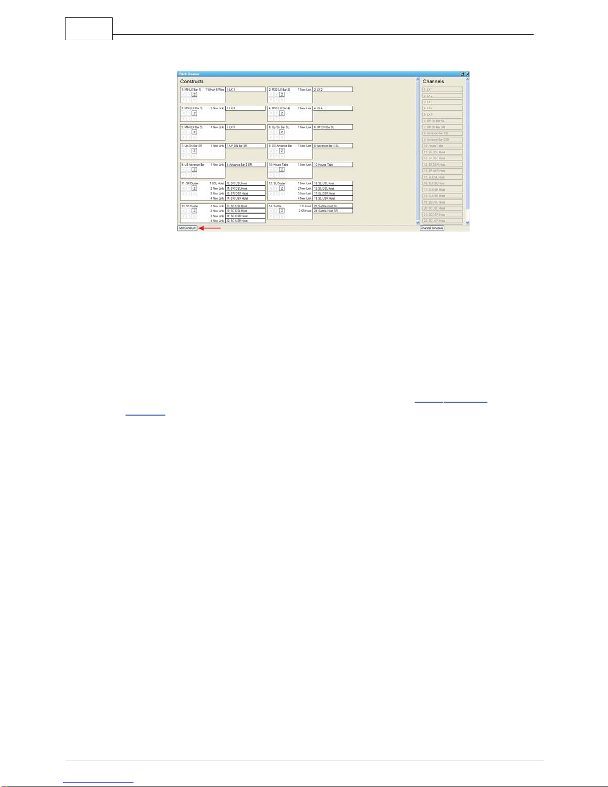
10 The Patch Browser
The Patch Browser contains a summary of all the Constructs, Channels, Links and
patching in your show. It is divided up into two areas. The left hand pane contains all
the Constructs in the show. Within each Construct are six icons representing the six
possible parameters of motion; X, Y, Z, P(pitch), T(tilt) and R(rotate). If a Construct has a
parameter enabled then the letter is in black, if it does not have access to a parameter
then the letter is in grey. To view the properties of an individual parameter either
double-click the letter or right-click and select Properties. To view properties for the
whole Construct double-click in the main Construct box or right-click and select
Properties.
15The Patch Browser
Links for each Construct are shown on the right hand side of the Construct box. Patched
Channels are displayed as white boxes containing the Channel name, un-patched Links
are shown as grey boxes with a dashed outline.
In the right hand pane are a list of all the Channels in the show. Patched Channels are
shown as grey boxes while un-patched Channels are shown in white. The properties of
an individual Channel patched or un-patched can be viewed by double-clicking an a
Channel’s box or by right-clicking and selecting Properties. To view the properties of
several Channels left-click on the relevant Channels while holding down the Ctrl key on
the keyboard then right-click one of the Channels and select Properties.
To patch a Channel to a Link on a Construct drag and drop the Channel onto the
dashed box beside the Construct box. To replace an existing Channel drop the new
Channel on top of the existing one. A confirmation box will appear, click Yes to finish the
patch or No to cancel the operation.
© 2010 Kinesys
16 K2
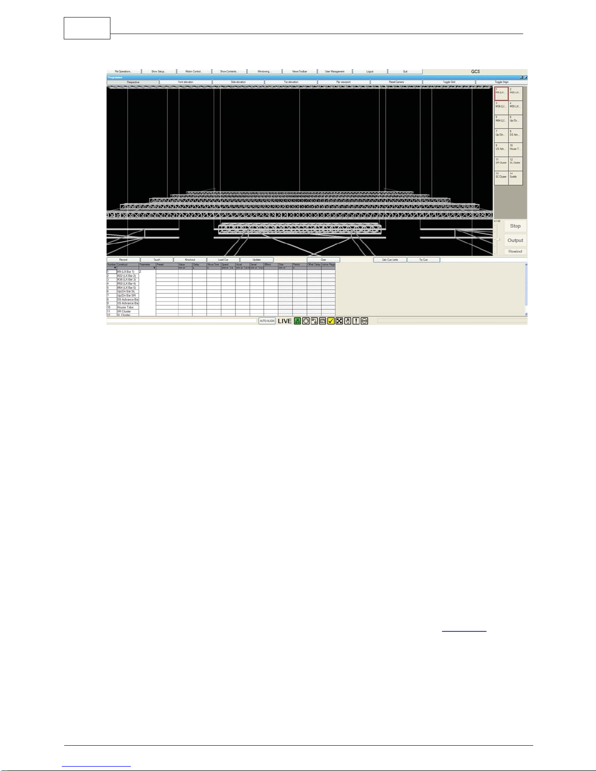
11 The Visualiser
On the Main Toolbar, press Visualiser to open the Visualiser. This allows you to see the
position of the Constructs in 3D space.
To move the camera in perspective view, click and drag the mouse left and right to
rotate about the origin of the stage, and drag up and down to vary the height above the
stage that you are viewing from. In the orthographic views, Front, Side and Top, the
mouse moves the viewpoint around the plane of projection. In all views the mouse wheel
will zoom the camera in and out.
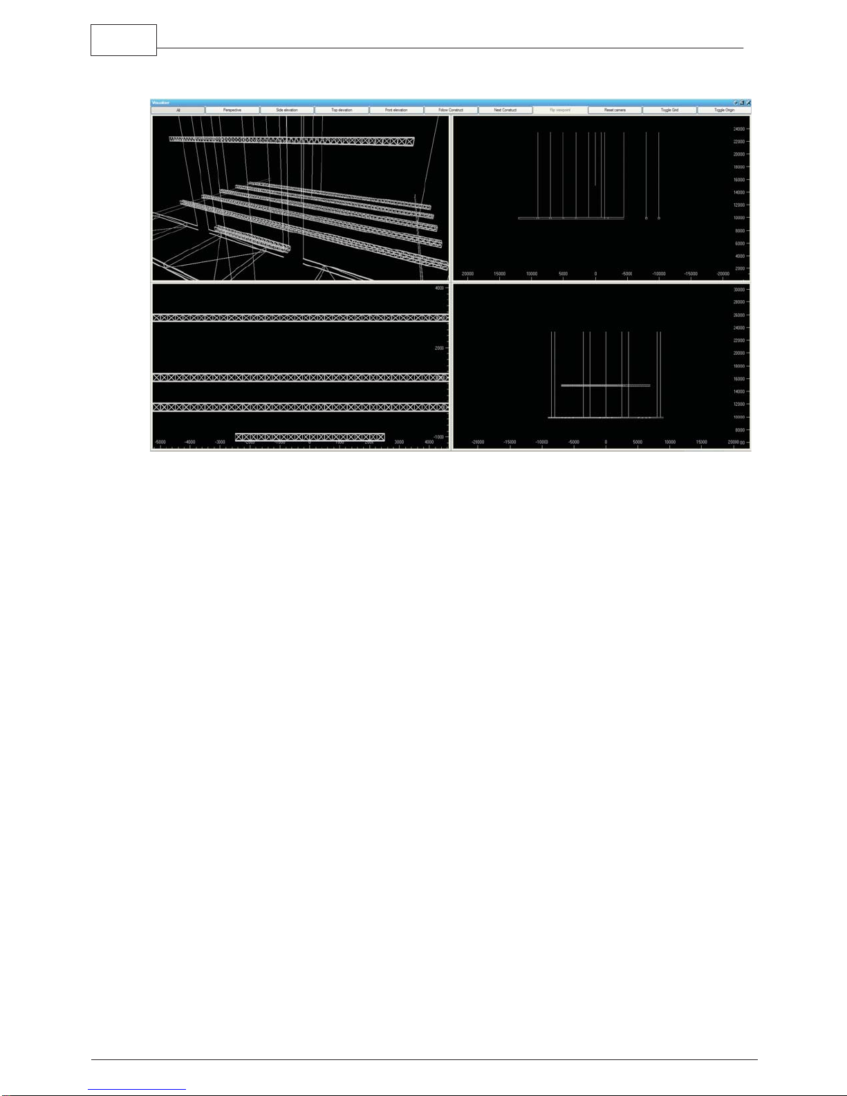
Use the toolbar buttons to toggle between the perspective view and orthographic
elevations, or to display them all. The projections are XY (front elevation), YZ (side
elevation) and XZ (top elevation). In all but the Perspective view, rulers are displayed at
the side of the viewer to help with approximating position. To show the world origin click
on Toggle Datum in the Visualiser toolbar. The Front, Side and Top views allow a grid to
be superimposed onto the Visualiser window. This makes using the rulers to
approximate position much simpler, to turn the grid on and off use the Toggle Grid
button on the Visualiser toolbar.
© 2010 Kinesys

12 Channel Alignment
Channel alignment is the process of connecting the virtual Channels to the physical
Channels. K2 knows where the Construct is in its 3D world and it knows where it thinks
that the Channels should be in order to achieve that position. The process of alignment
confirms that the two match and can therefore be controlled. Channels are considered
to be aligned when the physical position of the moving item on the stage matches the
position displayed within K2. If there is a difference between the two positions then
either the 3D representation must be moved to match the real world or the physical
object must be moved to match the position that K2 is displaying.
Once the two worlds are aligned the relevant Channels can be enabled and K2 can take
control of the moving object.
Channel Alignment is always required when a show is loaded into K2, it is also required
whenever movement has been initiated through the Direct
To enable a Channel either double click on ‘No’ in the Enabled column or click on the
cell and press Insert. If you wish to enable all Channels then click on the Enable All
button at the bottom of the window.
17Channel Alignment
MotorControl window.
There may be occasions where you wish to disable the Channel Alignment so that you
can move objects in the real world without affecting the virtual one or vice versa. To
access the Channel Alignment window, click the Channels button on the main toolbar.
From the Channels window click on the Channel Alignment button. This window will only
appear if you have linked Channels in your show and if those Channel controllers are
connected to the system.
Auto Alignment
There is now an Auto Align button on the toolbar of K2. This button aligns the virtual
objects in K2 to the real world positions of the objects, allowing K2 to realign itself
without any movement in the real world. If you are using K2 with Constructs that only
have a Z axis movement, this is especially useful. Dealing with Constructs that have
more than one axis makes the Auto Alignment harder to achieve, as there are obviously
far more variables, but K2 will still do it's best to auto align. The Auto Align feature uses
the information that K2 has about the real world positions of Constructs and Channels to
match the virtual positions to them. Once this alignment has been achieved, K2 will
allow movement to continue
For more information on the functions of this window see the Channel
of the Window
chapter.
Alignment section
© 2010 Kinesys
18 K2
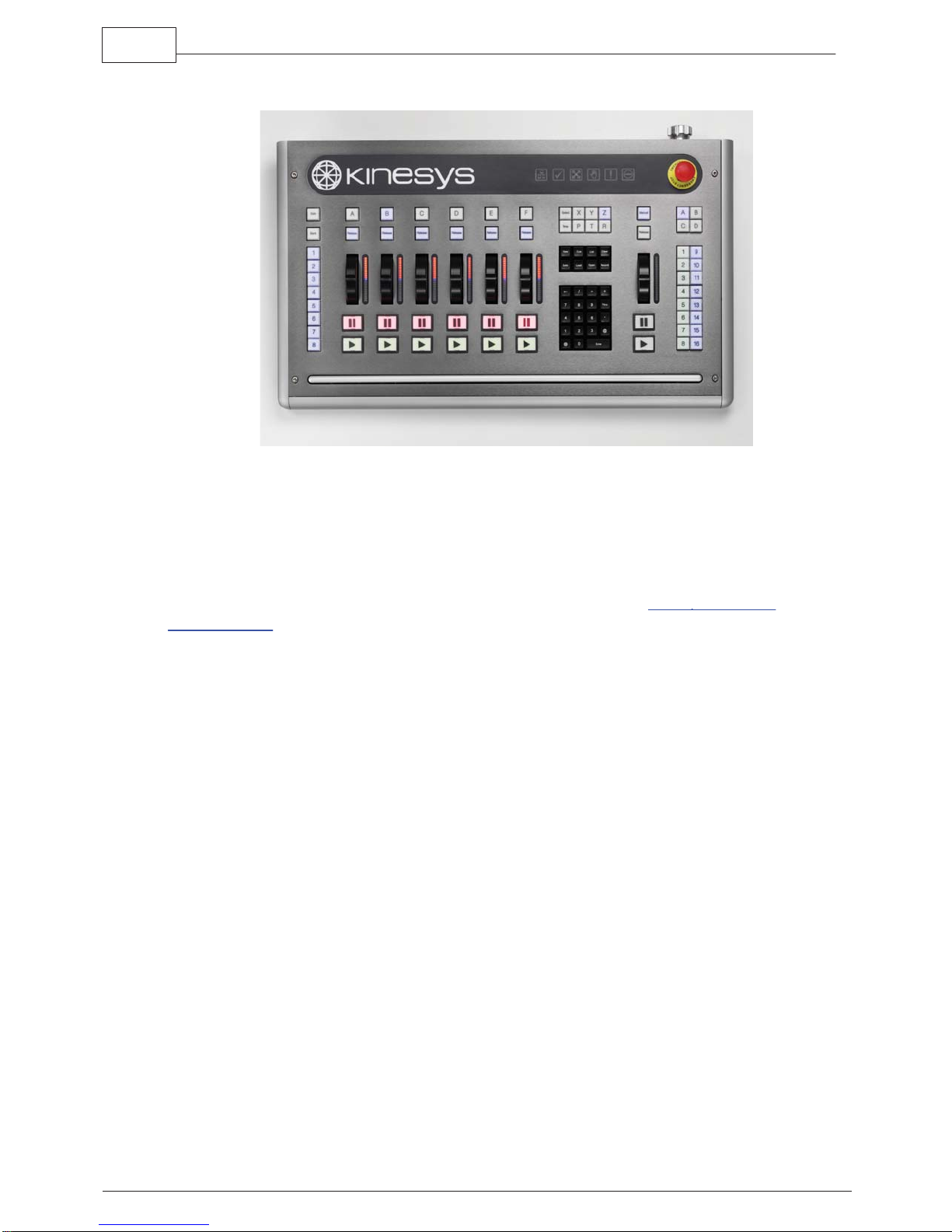
13 Console
K2 is available as self contained console, which contains the computer hardware that
runs K2 as well as providing a control surface, keyboard and mouse. The console offers
a whole range of selection and programming possibilities that are not available through
the keyboard and mouse alone. Although this manual primarily concerns itself with the
K2 software, where appropriate the wing commands and shortcuts will also be listed.
To adjust settings relating to a connected K2 console click on Show
Setup
toolbar and then click on the Wing tab. From here the brightness of the desklight,
Properties from the
bargraph indicators and illuminated keys can be set. The serial number and firmware
revision of the console can also be read from here. Finally firmware can be reloaded to
the wing from this tab. Click on the Reload Firmware button to have K2 reload the latest
version of the firmware to the console.
© 2010 Kinesys

14 Setting up a Show
The following areas outline the steps to take when setting up, saving and backing up a
show. For further information on the properties of a show see the Show
section.
Creating a New Show
On the main toolbar click on File then New Show. You will be prompted to select a
filename for the show and a folder to store the show in. Once both of these have been
entered click on OK.
Loading an Existing Show
On the main toolbar press File then Load Show. Select a show from the dialog and then
click on OK.
Once the show has been loaded you will be asked to align the Channels. This process
locks the position of the physical machines (motors, winches, rams etc.) to the virtual
Channels within K2. See Channel
Saving a Show
On the main toolbar click on File then Save Show. This will save all changes to disk.
19Setting up a Show
Properties
Alignment for more details.
Backing up a Show
Use Backup to save a copy of the existing show for archiving purposes. On the main
toolbar click on File then Backup. You will prompted to enter a new filename and/or new
folder for the backup file. Click on OK to save the backup copy. Subsequent saves will
use the current filename and location. Backup purely saves a snapshot copy of the file.
Automatic Backup
Automatic backup performs background saves of the show so that should the
application stop running for any reason a minimal amount of programming will be lost.
The Auto Backup feature is turned on and off in the Show Properties window which is
accessed by clicking on Setup and then Show Properties. Select the check box to turn
Auto Backup on and then choose how many generations of backup file you wish to
maintain as well as the frequency of the automatic saves.
Advanced Properties
The advanced tab contains variables relating to the low-level running of the motion and
communications software engines. These should not be adjusted unless you are
specifically requested to do so by a member of the Kinesys support team or one of their
approved K2 partners.
© 2010 Kinesys

20 K2
15 Show Properties
The show properties are global settings that apply to the whole show and are applied to
all data. This window allows you to choose the world model, define the security settings
for the show and adjust properties relating to the wing. For full details of the contents of
this window refer to Show
Properties in the Window chapter of this manual.
To access the Show Properties window click on Show
Setup and then Show Properties.
© 2010 Kinesys
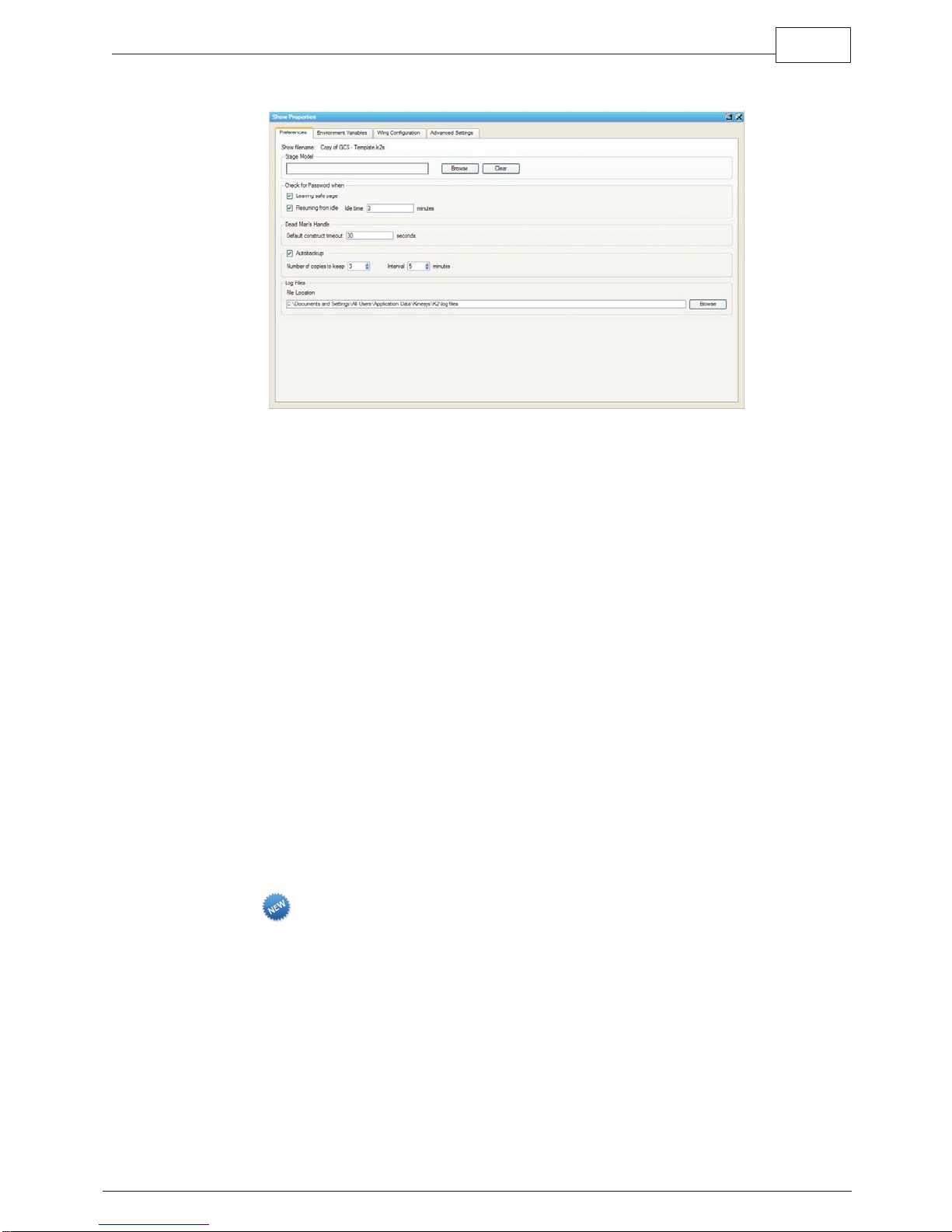
15.1 Properties
Stage Model
To set the stage model for the visualiser and programmer click on Setup on the main
toolbar and then Show Properties. Click on the Show Data tab and then on Browse in
the Stage Model section. Select the required .3ds file and click on OK. Exit the window
by clicking on the Close cross in the top right hand corner of the window.
21Show Properties
Password Checking
K2 can be set to request password confirmation when exiting Safe mode and also after
a period of inactivity. These can be turned on and off individually. Click on Show
Properties from the Setup toolbar and then set the check boxes appropriately to set the
password protection appropriately.
Dead Man's Handle
The default Construct timeout specifies the time that will be applied to all Constructs
when they are created. The dead man’s handle must be activated on a Construct by
Construct basis from its default disabled state if you wish to use it. The timeout can also
be varied for each Construct if you so desire. Details of these settings can be found
under Edit Construct in the Window Detail section of this manual.
Auto Backup
This turns on the automatic show backup feature. Refer to the Auto Backup section of
the Working with Files chapter above for more details.
Log Files
K2 will automatically set the log files to save to Documents and Settings/All
Users/Application Data/Kinesys/K2/log file. You also have the option of specifying this
path yourself, so if you wanted to set the log files to save to an external hard drive or a
server (so they were accessible remotely) that is very easy to setup.
© 2010 Kinesys
22 K2
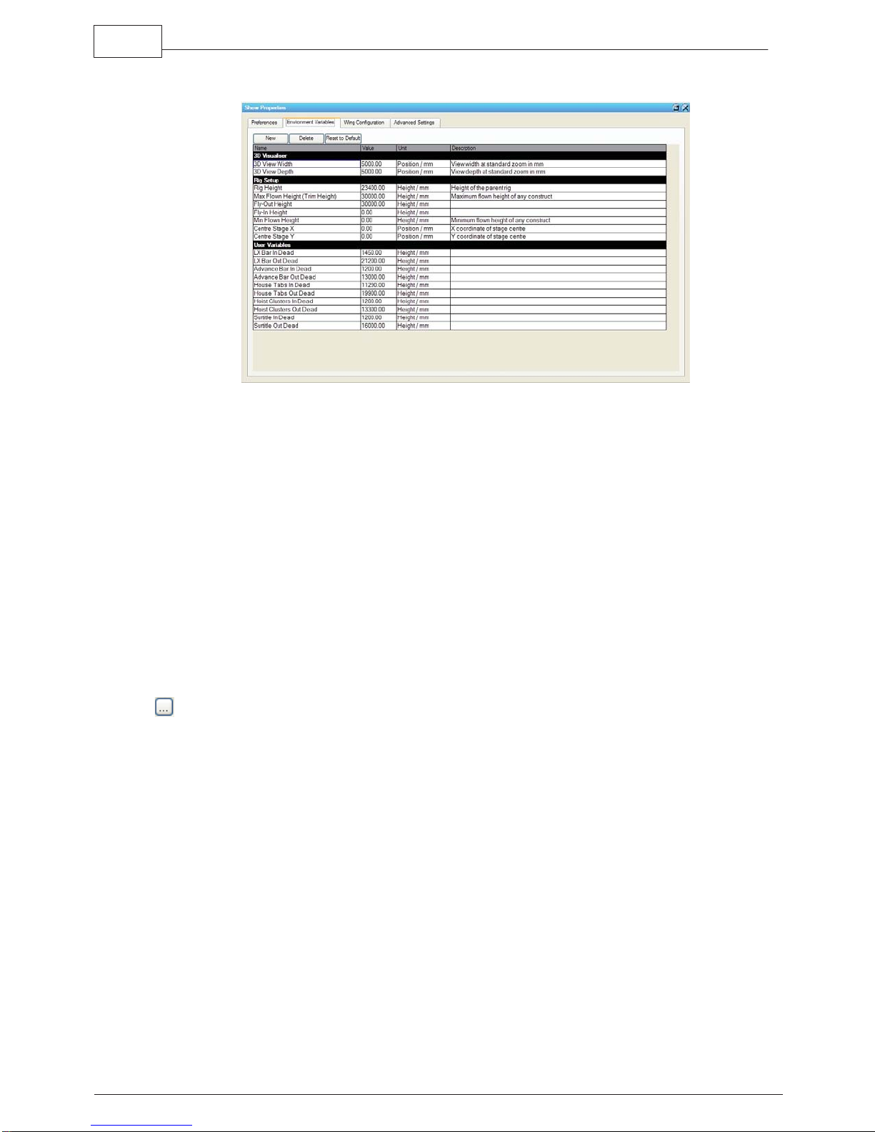
15.2 Environment Variables
K2 has a number of global show variables that can be referenced throughout the
application but can only be changed in one place. Anything that references a show
variable will therefore be affected whenever the show variable is altered. The system
comes with a number of preset variables but new ones can be added if you wish.
Variables are categorised by type e.g. height, angle, speed. The value of the default
variables can be altered but not the name of the variable type.
Creating a New Variable
Click on Show Properties from the Setup toolbar. Click on the Environment Variables tab
and then on New. A new variable will be added to the end of the variable list. Scroll to
the end of list and double click on the appropriate field to edit the name, value or type.
Once declared this new variable can be accessed from any relevant field within the
application.
Referencing Variables
Throughout the application the show variables can be accessed whenever you see the
symbol at the end of a number field. Click on the symbol and a list of show variables
of the correct type will be shown. For example you will not see Speed variables for fields
relating to Position.
Offsets can also be applied to show variables. After you have selected the correct show
variable add a + or – symbol and then the offset you require. E.g. maximum value for a
Z parameter can be set to ‘Rig Height – 1000’ if you want the maximum to always be one
meter below whatever value the rig height is set to.
© 2010 Kinesys
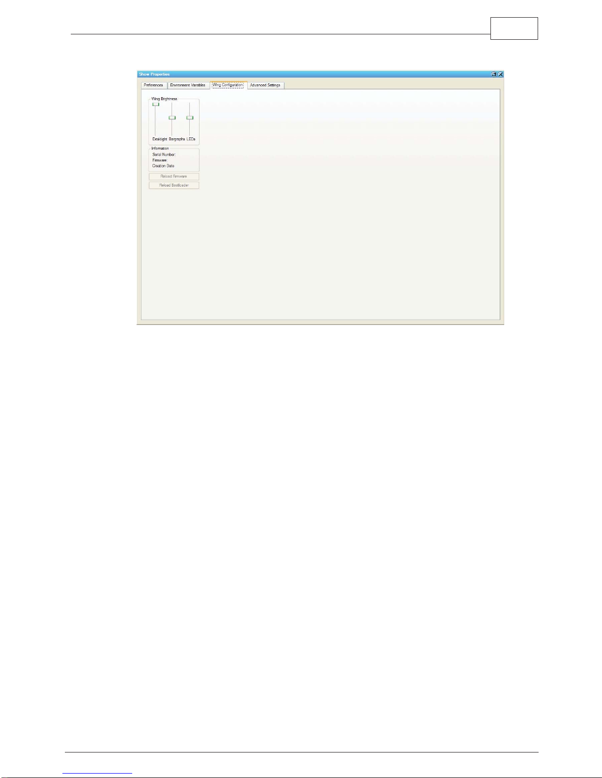
15.3 Wing Configuration
23Show Properties
The Wing Configuration tab contains options for altering the brightness of the LEDs in
the wing, retrieve information from it including serial number and firmware and reload or
update the firmware on the wing.
© 2010 Kinesys
24 K2
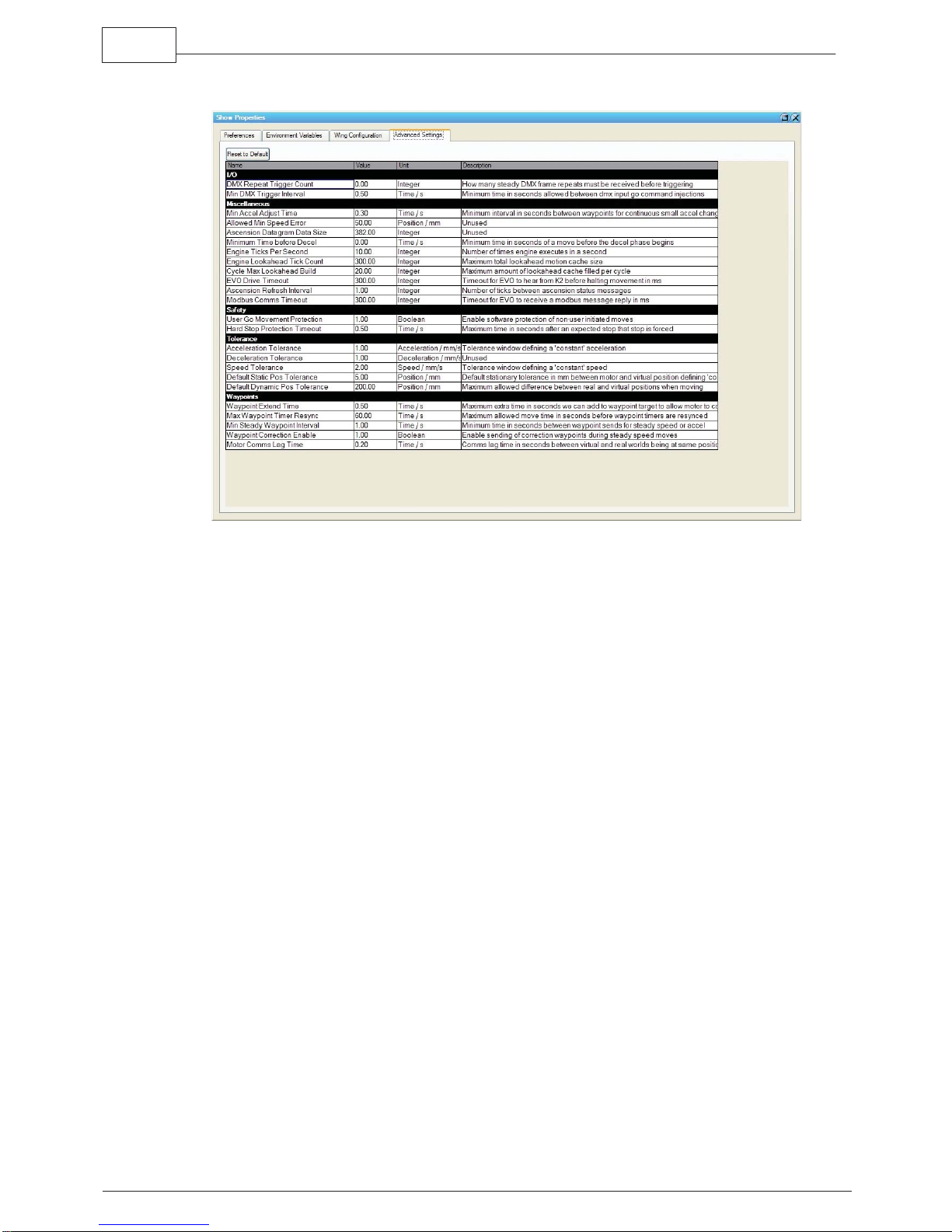
15.4 Advanced Settings
The Advanced Settings tab allows fine tuning of advanced settings within K2. It is
strongly advised that these settings are not altered without prior consultation with
Kinesys or associated partners, see the Contact Us section of this manual for contact
details.
© 2010 Kinesys

16 Construct Building and Editing
A Construct represents a moving item within K2. You will need to add one Construct for
every item you wish to control. It is important to remember when creating constructs (or
entering any information into K2) that the results that K2 produces are only as good the
information that is entered. If incorrect information is given to K2, then the results that K2
outputs will also be incorrect.
25Construct Building and Editing
© 2010 Kinesys
26 K2
16.1 Adding Constructs
To add a Construct to your show click on Setup on the main toolbar and then click on
Patch Browser, within the Patch Browser window click on Add Construct .
Alternatively if you have already created a Construct of the required type and you simply
wish to duplicate the type and basic settings then open the Browser by clicking on
Setup on the main toolbar and then Patch Browser. Find the Construct to be copied and
right click on it. From the drop down menu select Clone. A duplicate Construct will be
created of the same type and with the same settings. The Edit Construct window will
open with the new Construct loaded. Change any settings as necessary and then click
on OK to load the new Construct into the show.
For more information on the functions of this window see the Patch
the Window
chapter.
Browser section of
© 2010 Kinesys
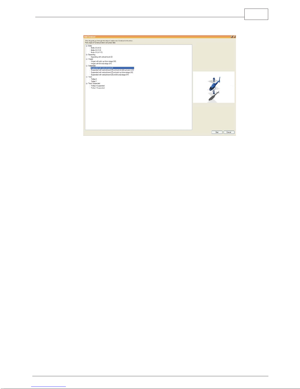
16.2 Selecting a Construct Type
An initial window will ask you to select the base Construct Type. A number of options
are available. Base Constructs are grouped by type using headings in the Construct
explorer part of the window. Under each heading are variations on the base type, if you
cannot see any variations under the heading expand it by clicking on the plus symbol
next to the heading. Select the type that is correct for the mechanical limitations of the
item you are modeling and then click on Start. This will open a multi-step dialog that will
ensure that you enter all the required information to define the Construct. On the left
hand side of the multi-step dialog are listed a number of steps. Next to each step is
either a cross or a tick. Once all the steps have been completed with the required
information the OK button will enable and the dialog can be closed and the Construct
created.
27Construct Building and Editing
To move from step to step you can click on the step name, use the Previous and Next
buttons in the bottom left of the window or by tabbing through the fields in each
tab.Once all fields have information correctly entered you will automatically move onto
the next step.
© 2010 Kinesys
28 K2
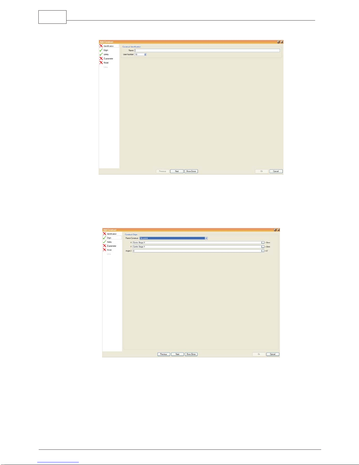
16.2.1 Identification
Enter a name for the Construct and pick a Construct number, the number must be
unique, the software will not allow selection of numbers that are already allocated to
previously created Constructs within the same show.
16.2.2 Origin
Specify the location of the origin of the Construct within the 3D world. You must specify
an X and Y co-ordinate. If the Construct does not lie directly along a co-ordinate axis
then its angle to that axis should be specified in the Angle Z (angle to the Z axis) field.
An example of this would be a flown straight truss. Its model will show it as a straight
© 2010 Kinesys
truss lying along the x axis, that is to say from stage right to stage left. If in reality that
truss is actually hung diagonally across the stage for the upstage right corner to the
downstage left corner then a value must be entered into the Angle Z field so that the
application knows to display this truss at an angle.
You can also specify if the Construct is a child of another Construct, this would be used
to accurately represent one truss suspended underneath another one in the 3D world.
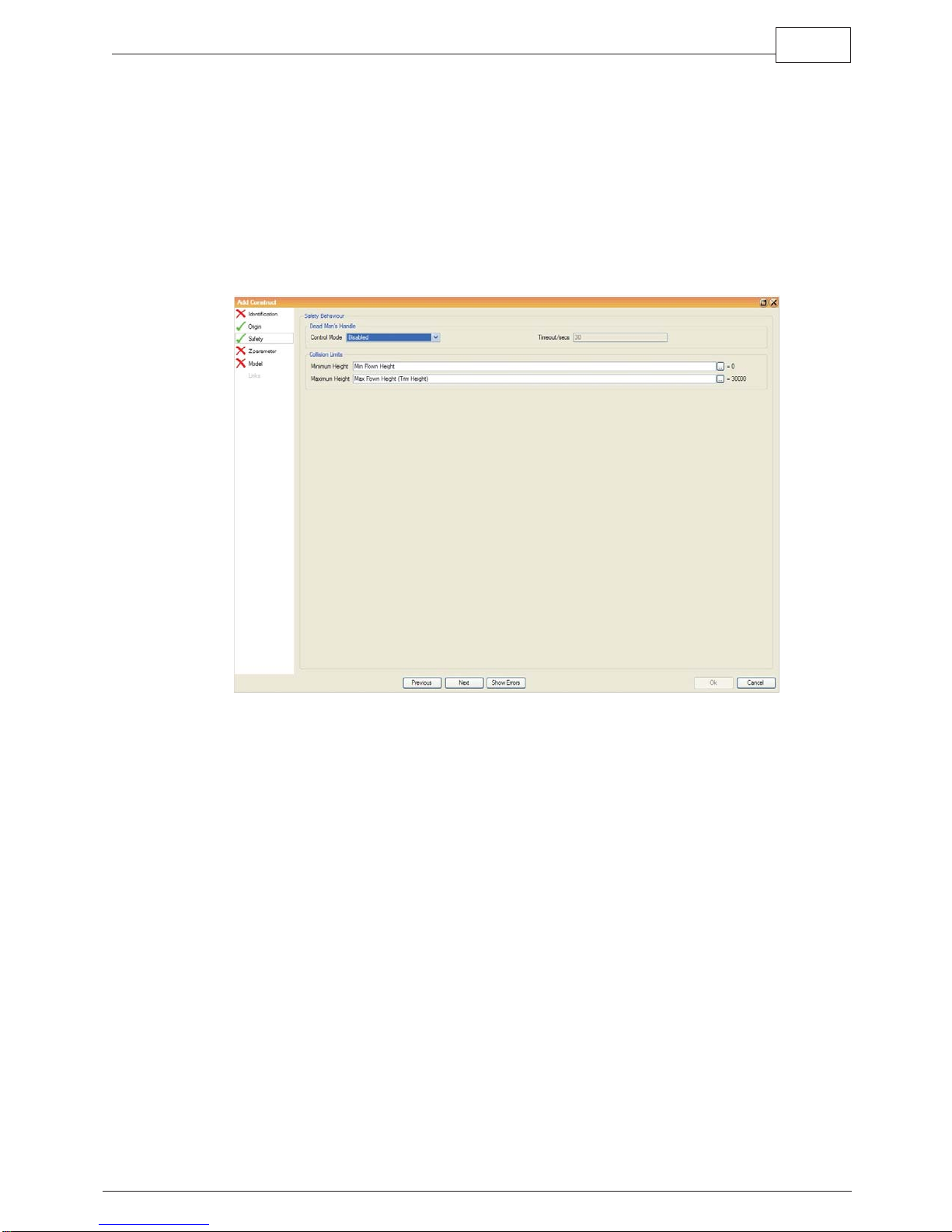
16.2.3 Safety
29Construct Building and Editing
In this step you set whether the Construct needs the Dead Man’s Handle (DMH) pressed
to allow movement. The default state is disabled, you can select Held for the DMH to be
pressed at all times when the Construct is moving or Periodic if the DMH must only be
pressed occasionally to maintain movement. If Periodic is selected you can set the
interval upon which the DMH must be pressed. By default it is set to the value specified
in the Show Properties but you can set it any value in units of one second.
A minimum and maximum collision limit must be specified to define the range of travel of
the Construct. These collision limits take into account the size and shape of the
Construct model and therefore protect against the Constructs colliding with other items
even though the individual Channels that control it may be within limits. By default the
collision limits reference two Environment Variables. The Environment Variables that
they use can be changed by clicking on the small button at the end of the text field and
selecting from the list presented. Alternatively an actual value can be entered directly
into the text field.
© 2010 Kinesys
30 K2
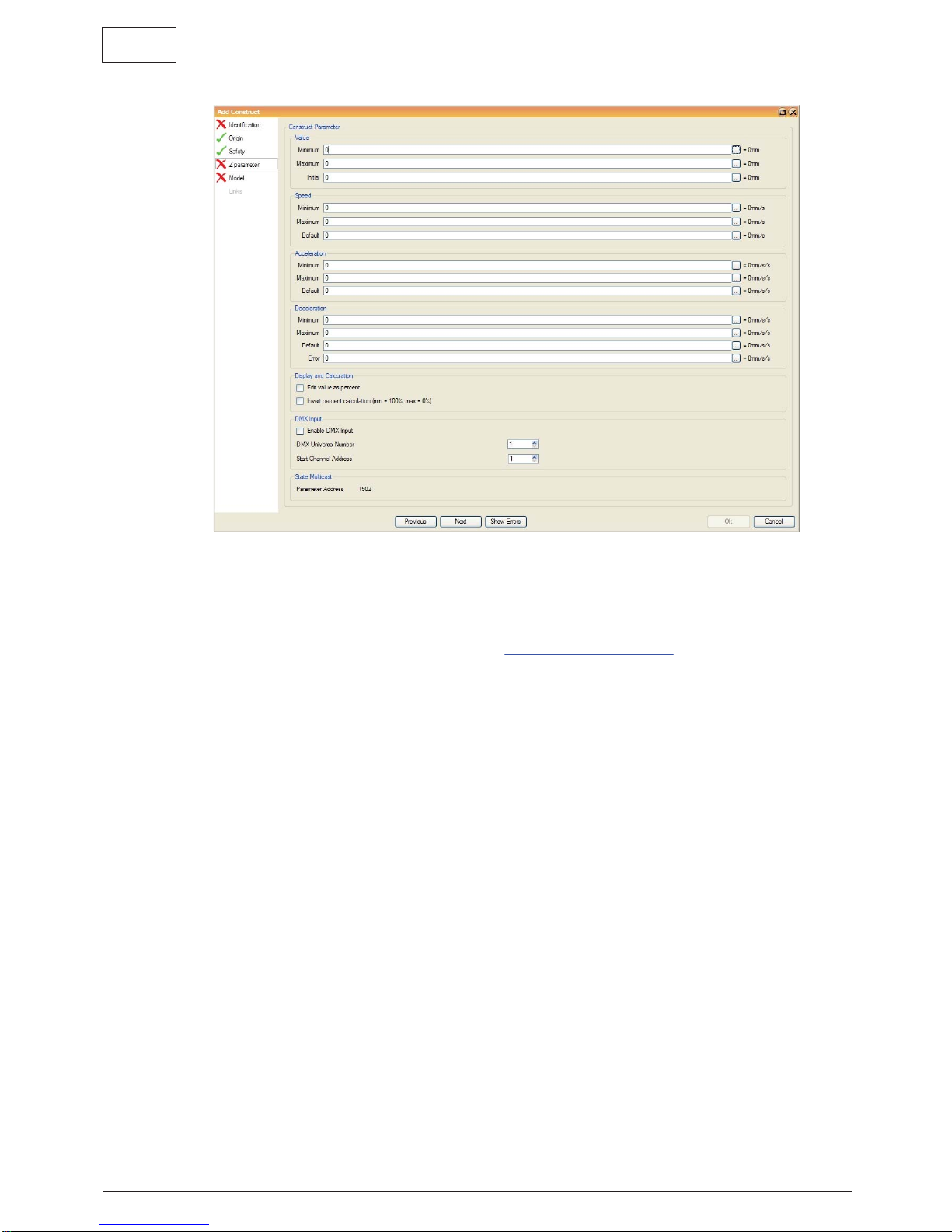
16.2.4 Parameters
Depending on the base Construct type selected, between one and six parameter steps
are required to be completed. Each parameter requires minimum and maximum values
to be entered for position, speed, acceleration and deceleration. In addition an initial
value is required for the position and a default value for the speed, acceleration and
deceleration. All these values can reference environment
variables if desired.
Value
Enter the minimum and maximum amount of travel you want in the direction that you are
editing, also enter the initial position that the Construct model should be displayed at
when it is first created. The units are in millimeters for all linear motion parameters, X, Y
and Z and in degrees for all angular motion parameters, Pitch, Tilt and Rotate.
Speed
Enter the minimum, maximum and default speeds that you wish the Construct to travel
at for the current parameter. The units are in millimeters/second for the linear motion
parameters, X, Y and Z and in degrees/second for the angular motion parameters, Pitch,
Tilt and Rotate. When selecting these values it is important to take into account the
maximum and minimum speeds of the machines attached to the Construct, otherwise
what is programmed in the 3D world will not be achievable in the real world.
Acceleration
Enter the minimum, maximum and default ramps that you wish the Construct to
accelerate at for the current parameter. The units are in millimeters/second/second for
the linear motion parameters, X, Y and Z and in degrees/second/second for the angular
© 2010 Kinesys
 Loading...