

Kinemetrics EpiSensor2 User Manual
K
NEEMMEE
RII
S
.
K
IIN
TTR
CCS
,, IInncc.
Strong Motion Accelerometer
EpiSensor2
User Manual
Document 305801
Revision A
August 2015


EPISENSOR2 USER MANUAL DOCUMENT 305801, REVISION A
Table of Contents
No User-Serviced Parts ................................................................................................................................. 1
Electrical Safety Notice ................................................................................................................................. 1
Introduction and Product Description .......................................................................................................... 1
Electrical Connections ................................................................................................................................... 2
EpiSensor2 Cabling ........................................................................................................................................ 4
Operational Control of the EpiSensor2 ......................................................................................................... 8
Full-Scale Ranges ....................................................................................................................................... 9
Button Pushing ...................................................................................................................................... 9
Digitizer Enable Lines (Q330 used for this description) ........................................................................ 9
RS-232 Command Line Interface ........................................................................................................... 9
AUTOZERO .............................................................................................................................................. 10
Button Pushing .................................................................................................................................... 10
Q330 Enable Lines (Q330 used for this description) ........................................................................... 10
RS-232 Command Line Interface ......................................................................................................... 10
CAL (Calibration) ..................................................................................................................................... 11
Q330 Enable Lines (Q330 used for this description) ........................................................................... 11
RS-232 Command Line Interface ......................................................................................................... 11
RESET ................................................................................................................................................... 11
Setup and Initial Operation ..................................................................................................................... 11
Operational Details ..................................................................................................................................... 12
Choice of Digitizer ................................................................................................................................... 12
Full-Scale Range Selection ...................................................................................................................... 12
AUTOZERO Mode .................................................................................................................................... 12
Calibration (CAL) ..................................................................................................................................... 13
Retention of Settings .............................................................................................................................. 13
Sensor Response Values ......................................................................................................................... 13
Input Power Requirements ..................................................................................................................... 13
Thermal Isolation .................................................................................................................................... 14
RS-232 Command Line Interface................................................................................................................. 15
Main Page Commands ................................................................................................................................ 16
Password Protection ............................................................................................................................... 17
Operate Page Commands ................................................................................................................... 17
i

EPISENSOR2 USER MANUAL DOCUMENT 305801, REVISION A
Response Page Commands ................................................................................................................. 18
Activity Timeout and Disable .............................................................................................................. 18
Seconds and Ticks ............................................................................................................................... 18
Shipping and Handling ........................................................................................................................ 18
Contact Kinemetrics ............................................................................................................................ 18
EpiSensor2 Specifications ........................................................................................................................... 19
Figures
Figure 1: EpiSensor2 module. ....................................................................................................................... 1
Figure 2: Sensor with standard cable. .......................................................................................................... 5
Figure 3: Standard cable with RS-232 cable connected. ............................................................................... 5
Figure 4: Pulse-train range signal for +/-4 g range. .................................................................................... 10
Figure 5: Details of leveling feet. ................................................................................................................ 12
Tables
Table 1: Connections to sensor through Souriau 851-07C16-26P50-A7-44 receptacle. .............................. 3
Table 2: Connection details of standard 6 meter cable. .............................................................................. 8
ii

EPISENSOR2 USER MANUAL DOCUMENT 305801, REVISION A
No User-Serviced Parts
The EpiSensor2 is a self-contained seismic accelerometer. There is no reason to open the sensor
package, or to modify the electronics or sensor elements contained within it. There are no internal
manual adjustments to make, nor are there any user-serviced parts within the sensor. Opening and/or
modifying the sensor is unnecessary, and doing so will void the instrument's warranty.
Electrical Safety Notice
As with all electrical instruments, potentially lethal potentials can be present on all metal
surfaces, including conductors within any cables. Proper grounding of these elements is
important to minimize these risks. The user of this product is responsible for its installation and
operation in a safe manner, and in accordance with all local requirements for electrical safety.

EPISENSOR2 USER MANUAL DOCUMENT 305801, REVISION A
Introduction and Product Description
The EpiSensor2 is an advanced force-balance, triaxial accelerometer that builds upon the
outstanding record of its predecessor, the EpiSensor (the world's first seismological-grade
strong motion accelerometer). The high dynamic range of the EpiSensor2 allows both weak and
strong motion recording from a single sensor.
The EpiSensor2 provides a broad set of electronically-controlled operational modes, including
range-switching (allowing 4g, 2g, 1g, 0.5g, and 0.25g peak, full-scale ranges), Offset removal
(AUTOZERO mode), and calibration. These modes can be controlled remotely, either via the
digitizer (using selected enable lines) or via an RS-232 command line interface. The sensor also
provides a pushbutton switch for local control. This allows an on-site user to select sensor fullscale range and AUTOZERO state (ON or OFF).
An important feature of the EpiSensor2 is its very low quiescent power consumption: under 350
mW. The sensor consumes 60% to 70% lower power than competing strong motion
accelerometers. This makes it ideal for remote, battery-powered applications.
The EpiSensor2, and its cabling, are designed for direct connection to Quanterra Q330-series
digitizers, as well as digitizers from the Kinemetrics “Rock” series.
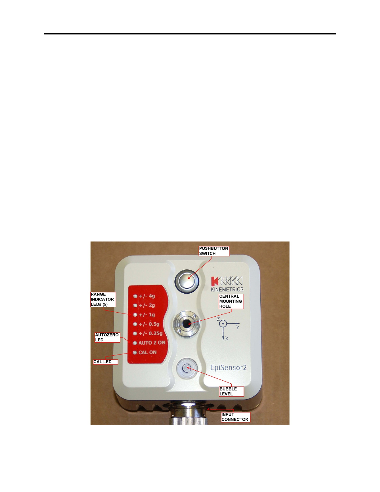
The EpiSensor2 module, and some of its features, are shown in Figure 1.
Figure 1: EpiSensor2 module.
Page 1 August 2015

EPISENSOR2 USER MANUAL DOCUMENT 305801, REVISION A
Electrical Connections
The EpiSensor2 contains a Souriau connector on its side. The connections supported by this
receptacle are shown in Table 1.
851-07C16-26P50-A7-44 Receptacle
Pin Designator
A Z Acceleration +
B Z Acceleration -
C Shield Connection Connected to
D Y Acceleration +
E Y Acceleration -
F Shield Connection Connected to
G X Acceleration +
Signal Notes
ANALOG Ground
ANALOG Ground
H X Acceleration -
J Shield Connection Connected to
ANALOG Ground
K Z Channel Range
Indicator
L Y Channel Range
Indicator
M X Channel Range
Indicator
N ANALOG Ground
Page 2 August 2015
 Loading...