

Page 1
TRUETIME
OPERATING
AND
SERVICE
MANUAL
"MODEL
468-DC-MRS"
Satellite Synchronized Clock
,.
0
...
'.,.,,
".,·.:
.. i
.:i
-~'
' •
~7
l •
";
•
"l
_j
,_
I •
_j
l I
~J
- •
"j
. )
NB,$,
TIME
KINEMETRICS/TRUETIME: 3243 SANTA ROSA AVE., SANTA ROSA,
CA
95407 (707) 528-1230 - TELEX 176687 - FAX (707) 527-6640
MANUAL DATED 10/86
Page 2
~
KINEMETRICS
"References
this
manual
468-DC
A-468MS
A-468RK
KINEMETRICS I TRUETIME
3243
Santa
Rosa
Ave.
Santa
Rosa,
CA
95407
May
in
to:
be
replaced
'by:
468-DC/MM
A-468MS/RK/MM-2
A-468RK/MM-2
11
Page 3
TRUETIME
KINEMETRICS
MARTIN MARIETTA CORPORATION
SAT
.RS
OP..DER
NO.
In
1982
Kinemetrics/TrueTime
redesigned
the
Models
A-468MS/RK
and
A-468RK
GOES
antenna
system.
The
newer
MK
II
version
of
the
Model
A-468MS/RK
has
a
different
circuit
card
and
has
different
dimensions
than
the
MK
I.
The
MK
II
antenna
is
still
compatible
with
the
MK I Remote
Kit,
and
the
MK
II
Remote
Kit
is
still
com-
patible
with
the
MK I antenna
as
far
as
function
is
concerned.
The
MK
II
version
of
the
Remote
Kit
also
has
a
different
circuit
card
and
different
dimensions.
When we
supplied
GOES
antennas
to
Martin
Marietta
in
1984,
we
were
able
to
remanufacture
MK
I
kits
from
resources
that
were
still
available
to
us.
Those
resources
are
no
longer
available.
Producing
MK I antennas
at
this
point
in
time
would
entail
an
ex-
tremely
prohibitive
expense
for
Martin
Marietta.
The
MK
II
GOES
antenna
system
is
now
the
only
version
available
to
us.
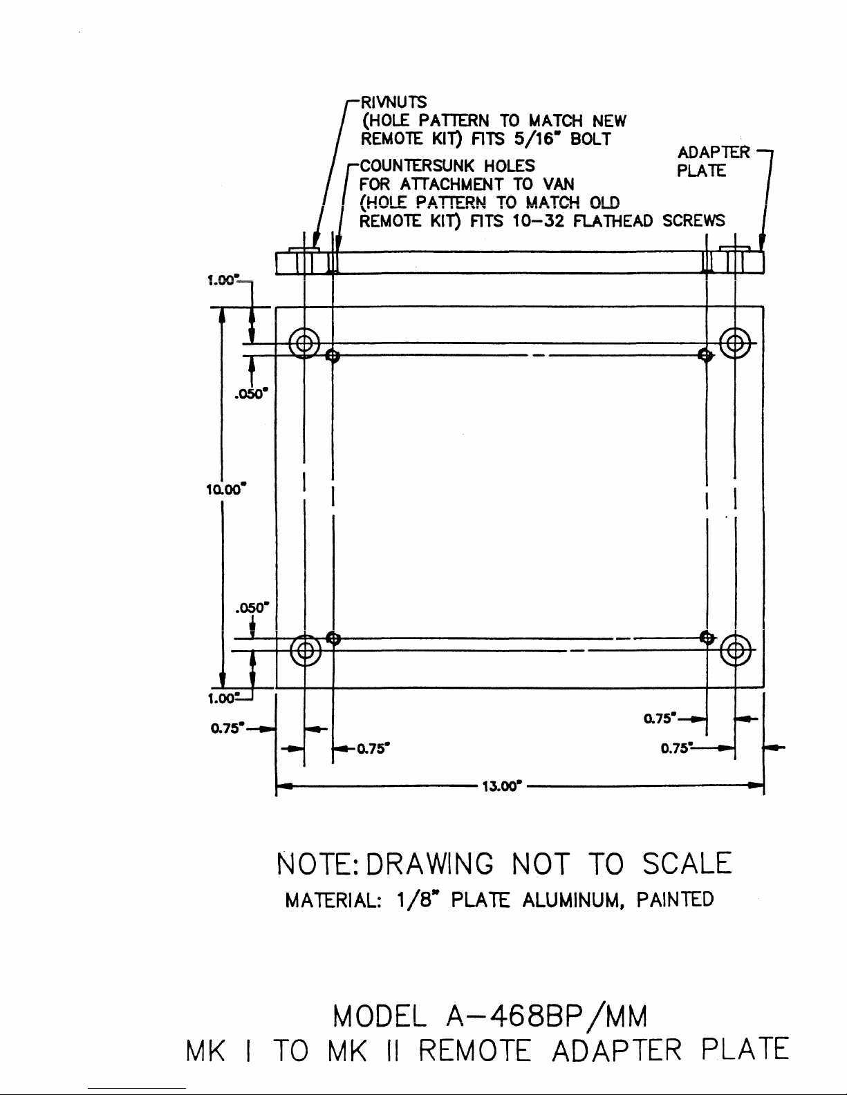
However,
we
can
still
accommodate
Martin
Marietta
van
application
by
providing
a
special
adapter
plate
to
be
installed
on
the
MK
II
Remote
Kit.
This
plate
will
allow
the
user
to
interchange
both
MK I and
MK
II
Remote
Kits.
Both
units
as
far
as
input/outputs
are
concerned.
are
The
mounting
holes
in
the
antenna
pedestal
baseplate
have
been
drilled
out
to
0.
459",
and
the
upright
mounting
stanchion
has
been
shorted
to
9.5"
to
conform
to
Martin
Marietta
Drawing
No.
850MROR0026.
Applicable
drawings
follow
this
page.
KINEMETRICS/TRUETIME: 3243 SANTA ROSA AVE., SANTA ROSA, CA 95407 (707) 528-1230 - TELEX 176687 - FAX (707) 527-6640
Page 4
·468DC-MRS
SYSTEM
DESCRIPTION
ITEM
-
l
2.
3
4
5
6
7
8
9
WARRANTY
PART
468~DC
NUMBER
MM
A-468MS/RK
A-468RK
MM
A-468Br/MM
A-468
A-468
MM -1.5
MM
- 20
A-468BC/MM
A-468AP1/MM
A-468PP1/MM
INFORMATION:
MM
2
DESCRIPTION
GOES
Satellite
GOES
Antenna Mark
Antenna Remote
Base
Plate
Cable Assembly
Cable
RG
214
"N" Bulkhead
Paint
Paint
Adapter
Assembly 20
with
"N"
Connector
Code 17925
Code 17925
Synchronized
II
Kit
for
Item
1.5
foot
length
Foot
length
Connectors
for
Item
for
Item
Clock
3
2 (White)
4 (White)
The
Kinemetrics/TrueTime
Kinemetrics/TrueTime's
perform
to
details.
their
warranty
end
user.
repairs.
Santa
Refer
design
to
of
the
468-DC-MRS
Rosa
factory
This
warranty
pages 1 through 3 of
is
the
is
transferable
is
considered
only
this
facility
from
manual
proprietary.
authorized
Martin
for
additional
to
Marietta
Page 5
APPENDIX
•A"
PAGE
DESCRIPTION
1
468-DC{MM ·
2
A-468MS/
~MM
3
A-468RK/MM· ·
4
A-468
BP/"·
MM·
Page 6
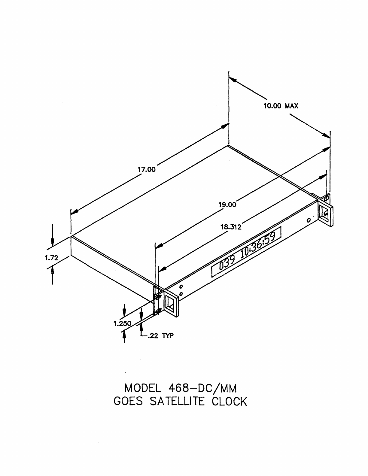
~
10.00
MAX
"'
<
T
MODEL
GOES
.22
TYP
468-DC/MM
SATELLITE
CLOCK
Page 7
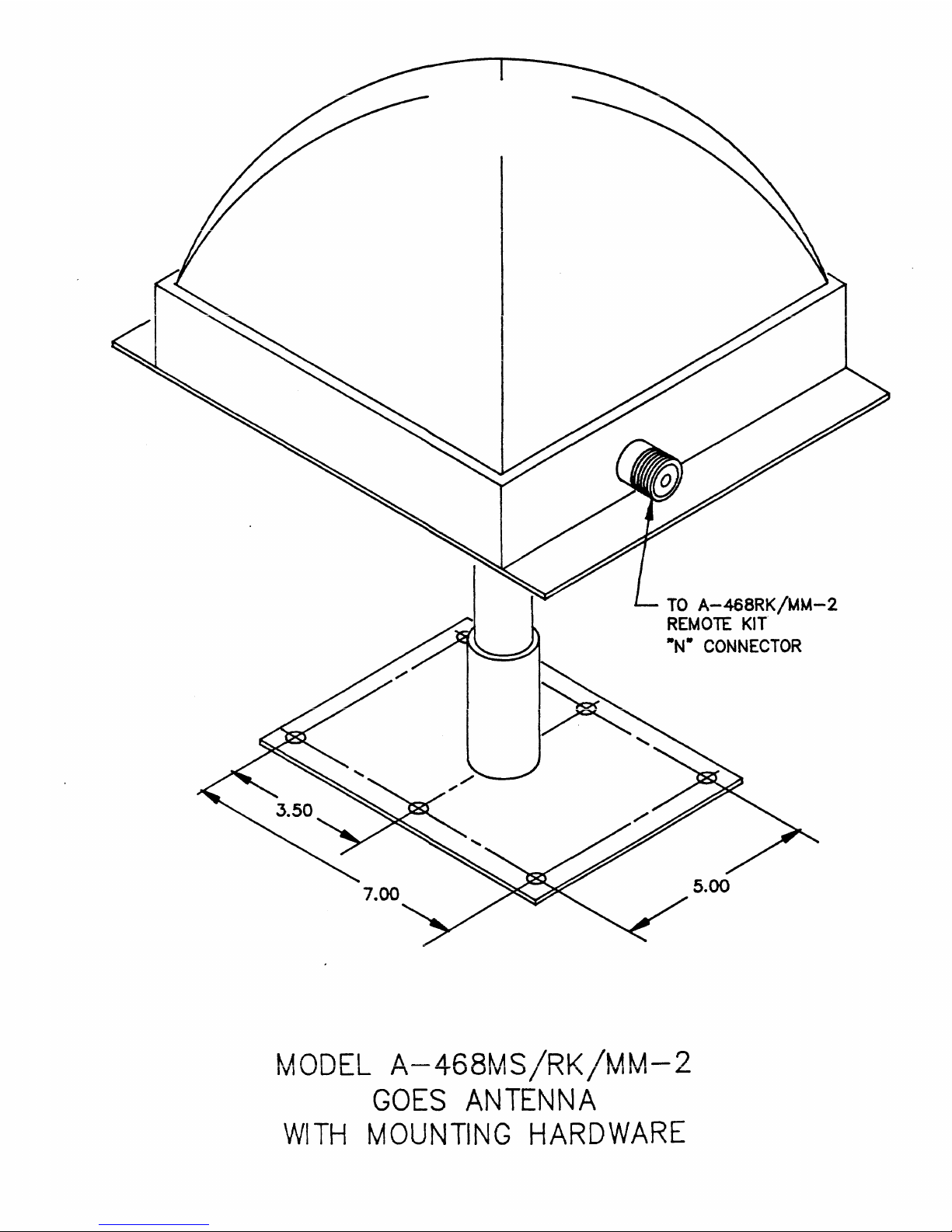
TO
A-468RK/MM-2
REMOlE KIT
"N•
CONNECTOR
~Annc-1
/\_.A~QU~
/DLt lt..At..A-?
IVIVLJLL
I\
IVUIVl....J/
l'I'/
1v11v1
'-
GOES
ANTENNA
WITH
MOUNTING
HARDWARE
Page 8
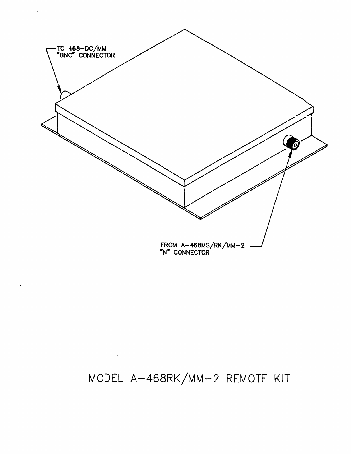
TO
468-DC/MM
·aNc·
CONNECTOR
FROM
A-468MS/RK/MM-2
•N•
CONNECTOR
MODEL
A-468RK/MM-2
REMOTE
KIT
Page 9
•
fV\._
··-
.050·
RIVNUTS
(HOLE
PATIERN
TO
MATCH
NEW
REMOTE
Kil)
FITS
5/16•
BOLT
ADAPTER
7
r
COUNTERSUNK
HOLES
PLATE
FOR
ATTACHMENT
TO
VAN
{HOLE
PATTERN
TO
MATCH
OLD
REMOTE
KIT)
FITS
10-32
FLATHEAD
SCREWS
10.00·
I I
1.00·
0.75•
......_------13.00•
-----------4
....
NOTE:
DRAWING
NOT
TO
SCALE
MATERIAL:
1/8•
PLATE
ALUMINUM,
PAINTED
MODEL
A-468BP
/MM
MK
I
TO
MK
II
REMOTE
ADAPTER
PLATE
Page 10
TABLE
OF
CONTENTS
SECTION
PAGE
I
GENERAL
INFORMATION
1-1
INTRODUCTION...................................
1-1
1-7
WARRANTY
.......................................
1-3
1-8
SPECIFICATIONS.................................
1-4
II
INSTALLATION
2-1
ANTENNA
INSTALLATION
................
~
..........
2-1
2-7
RACK
MOUNTING..................................
2-4
2-9
INSTRUMENT
START-UP
............................
2-4
III
OPERATION
3-1
3-3
3-7
3-11
3-13
3-16
3-18
3-24
3-26
3-28
3-36
3-41
3-45
3-51
3-55
3-66
3-74
3-7 5
3-79
3-84
3-88
3-92
3-94
3-97
3-98
3-104
3-106
3-114
3-123
3-125
'"\ 1 '"\
/""\
.)-1.)U
3-133
3-134
3-135
INTRODUCTION
..................................
.
SATELLITE
EAST-WEST
LED
.......................
.
DISPLAY
.......................................
.
HOURS
OFFSET
..................................
.
12/24
HOUR
CLOCK
OPERATION
....................
.
AUTOMATIC/MANUAL
SATELLITE
SELECTION
..........
.
PROPAGATION
DELAY
.............................
.
1 Hz
•••••••••••••••••••••••••••••••••••••••••••
1 KHz
•.•••••••••••.••••.....•.•.•••••••••••••••
IRIG-B
(REMOTE
DISPLAY
DRIVING
OUTPUT)
........
.
SLOW
CODE
.....................................
.
C..()
u~
vu
11~
•
•••••••••••••••••••••••••••••••••••••••••
EXTERNAL
OSCILLATOR
(Option)
..................
.
IRIG-H
(Opt
ion)
...............................
.
PARALLEL
BCD
TIME
OUTPUT
(Option)
.............
.
RS-232
TIME
OUTPUT
(Option)
...................
.
RS-232
MODE
DESCRIPTIONS
......................
.
MODE C ........................................
.
MO
DE
T
•••••••••••••••••••••••••••••••••••••••••
M 0
DE
F
•••••••••••••••••••••••••••••••••••••••••
MODE M ........................................
.
MODE P ........................................
.
MODE R ........................................
.
NOTES
.........................................
.
MODE
U -
DUT1
MODE
............................
.
M
0
DE
E . . . . . . . . .
...............................
.
I
-MODE
- (Opt
ion)
.............................
.
DAMS/HEALTH
MESSAGE
SOFTWARE
(Option)
.........
.
DAMS/HEALTH
MESSAGE
SET
UP
KEY
STROKESo••······
VERIFICATION
KEY
STROKES
......................
.
3-1
3-1
3-4
3-4
3-5
3-5
3'.'""5
3-7
3-8
3-8
3-9
3=9
3-10
3-10
3-11
3-15
3-19
3-19
3-19
3-20
3-21
3-21
3-22
3-22
3-23
3-24
3-24
3-25
3-27
3-27
DAMS/HEALTH
MESSAGE
INFORMATION
KEY
STROKES
....
3-29
OPERATING
NOTES
................................
3-29
IEEE-488
OUTPUT
(Option)
.......................
3-30
INTRODUCTION
...................................
3-30
1
Page 11
TABLE
OF
CONTENTS
(cont.)
SECTION
PAGE
III
OPERATION
(cont.)
3-137
3-140
3-142
3-146
3-151
3-156
3-158
3-161
3-165
3-167
3-170
3-173
3-177
3-179
HARDWARE.
. . . . . . . . . . . . . . . . . . . . . . . . . . . . . . . . . . . . . .
3-30
EXTERNAL
TRIGGER
...............................
3-31
SOFTWARE.
. . . . . . . . . . . . . . . . . . . . . . . . . . . . . . . . . . . . . .
3-31
MODE
F
.........................................
3-31
MODE M .........................................
3-32
MODE N .........................................
3-33
MODE P .........................................
3-33
MODE T .........................................
3-34
SAMPLE
PROGRAMS
. . . . . . . . . . . . . . . . . . . . . . . . . . . . . . . .
3-
3 5
D.C.
POWER
INPUT
(Option)
......................
3-37
SOus
TIMING
(Option)
...........................
3-37
DAYLIGHT
SAVINGS
TIME
CORRECTION
.......•.......
3-38
RS-232
STANDARD
MODES
.........................
3-38
ADVANCED
PERFORMANCE
OPTION
....................
3-39
IV
THEORY
OF
OPERATION
4-1
4-16
4-17
4-19
4-21
4-26
4-31
4-34
4-36
4-38
4-42
4-47
4-52
4-58
4-61
4-64
4-68
4-71
4-75
4-77
4-81
4-84
4-87
4-90
4-102
4-103
4-105
4-107
4-119
THEORY
OF
OPERATION
MODEL
468-DC
..............
.
DETAILED
DESCRIPTION
OF
OPERATION
.............
.
ACTIVE
ANTENNA
ASSEMBLY
86-170
................
.
PRE -AMP
L I F
IE
R . . . . . . . . . . . . . . . . . . . . . . . . . . . . . . . . . .
lST L.O.
MUL'NPLIER/MIXER
.....................
.
INTERMEDIATE
FREQUENCY
AMPLIFIER
..............
.
DETECTOR
BOARD
ASSEMBLY
86-73
.................
.
ANALOG
BOARD
ASSEMBLY
86-74
...................
.
RF
LOCK
DETECTOR
..............................
.
RF
LOCK
LOOP
..................................
.
DATA
DETECTOR
.................................
.
DATA
LOCK
DETECTOR
............................
.
COARSE
PHASE
LOCKED
LOOP
.......•...............
FINE
DATA
PHASE
LOCKED
LOOP
...................
.
EXTERNAL
OSCILLATOR
INPUT
(Option)
............
.
TIMING
CHAIN
..........................•......•.
DIGITAL
BOARD -ASSEMBLY
86-42
................
.
POWER
SUPPLY -ASSEMBLY
86-52
...............•..
DISPLAY
BOARD -ASSEMBLY
86-43
....•............
PARALLEL
BCD
TIME
OUTPUT
(Option)
-
ASSY.
86-44
RS-232
INTERFACE
(Option)
-
ASSEMBLY
86-46
.....
DAMS/HEALTH
MESSAGE
(Option)
..................•
IEEE-488
INTERFACE
(Option)
-
ASSEMBLY
86-47
..
.
D.C.
POWER
INPUT
(Option)
.....................
.
SOFTWARE
......................................
.
PROGRAM
DESCRIPTION
...........................
.
RECEIVER
CONTROL
AND
DATA
PROCESSING
..........
.
DESCRIPTION
OF
THE
STATE
DIAGRAMS
...•........•.
TIMING
OUTPUTS
................................
.
2
4-1
4-6
4-6
4-6
4-6
4-7
4-8
4-8
4-8
4-8
4-9
4-11
4-13
4-14
4-15
4-16
4-16
4-17
4-17
4-17
4-18
4-18
4-18
4-18
4-20
4-20
4-20
4-20
4-26
Page 12
V
MAINTENANCE
AND
TROUBLESHOOTING
5-1
MAINTENANCE
MODEL
468-DC
.......................
5-1
5-4
THIRD
I.F.
TRIM
-
AS~EMBLY
86-73
...............
5-1
5-8
DATA
SYMMETR~
ADJUSTMENT -ASSEMBLY
86-74
......
5-2
5-10
EAST
SWEEP
TRIM -ASSEMBLY
86-74
...............
5-2
5-12
WEST
SWEE?
TRIM -ASSEMBLY
86-74
...............
5-3
5-14
10
MHz
FINE
TIMEBASE
TRIM -ASSEMBLY
86-74
.....
5-3
5-16
1
MHz
COARSE
TIMEBASE,
ASSEMBLY
86-74
..........
5-3
5-18
FIRST
LOCAL
OSCILLATOR
PEAKING,
ASSEMBLY
86-74.
5-3
5-22
TROUBLESHOOTING
................................
5-4
5-49
TROUBLESHOOTING
THE
EXTERNAL
OSCILLATOR
(Opt.).
5-8
5-51
TROUBLESHOOTING
THE
D.C.
SUPPLY
(Option)
.......
5-8
VI
SCHEMATICS
AND
PARTS
LISTS
6-1
6-2
6-3
6-4
6-5
6-6
6-7
6-8
6-9
6-10
6-11
6-12
6-13
6-14
6-15
6-16
6-17
6-18
6-19
6-20
6-21
6-22
6-23
6-24
6-25
6-26
6-27
6-28
6-29
6-30
6-31
6-32
6-33
PARTS
LOCATION -ASSEMBLY
86-170
..............
.
SCHEMATIC -ASSEMBLY
86-170
...................
.
SYMBOL
DESIGNATION
REFERENCE
86-170
...........
.
PARTS
LOCATION -ASSEMBLY
86-173
..............
.
SYMBOL
DESIGNATION
REFERENCE
86-173
...........
.
SCHEMATIC -ASSEMBLY
86-173
...................
.
PARTS
LOCATION -ASSEMBLY
86-73
...............
.
SYMBOL
DESIGNATION
REFERENCE
8r
~1
............
.
SCHEMATIC -ASSEMBLY
86-73
....................
.
PARTS
LOCATION -ASSEMBLY
86-74
...............
.
SCHEMATIC -ASSEMBL'-
96-74
....................
.
SYMBOL
DESIGNATION
R~iERENCE
86-74
............
.
PARTS
10CATION -ASSEMBLY
86-42
.............
.
SYMBOL
DESIGNATION
REFERENCE
86-42
............
.
SCHEMATIC -ASSEMBLY
86-42
....................
.
PA~TS
LOCATION -ASSEMBLY
86-43
.........
~-
.....
.
SYMBOL
G:SIGNATION
REFERENCE
86-43
............
.
SCHEMATIC -ASSEMBLY
86-43
....................
.
PARTS
LOCATION -ASSEMBLY
86-44
...............
.
SYMBOL
DESIGNATI0N
REFERENCE
86-44
............
.
SCHEMATIC -ASSEMBLY
86-44
....................
.
PARTS
LOCATION -ASSEMBLY
86-46
...............
.
SYMBOL
DESIGNATION
REFERENCC
86-46
............
.
SCHEMATIC -ASSEMBLY
86-46.
,
................
.
PARTS
LOCATION
-
ASSEMBLY~:
-47
...............
.
SYMBOL
DESIGNATION
REFERENCE
86-47
............
.
SCHEMATIC -ASSEMBLY
86-47
....................
.
PARTS
LOCATION -ASSEMBLY
86-52
...............
.
SYMBOL
DESIGNATION
REFERENCE
86-52
............
.
SCHEMATIC -ASSEMBLY
86-52
....................
.
PARTS
LOCATION -ASSEMBLY
86-147
..............
.
SYMBOL
DESIGNATION
REFERENCE
86-147
...........
.
SCHEMATIC -ASSEMBLY
86-147
...................
.
3
6-2
6-3
6-4
6-6
6-6
6-7
6-8
6-8
6-9
6-10
6-11
6-12
6-14
6-14
6-15
6-16
6-16
6-17
6-18
6-18
6-19
6-20
6-20
6-21
6-22
6-22
6-23
6-24
6-24
6-25
6-26
6-26
6-27
Page 13
VI
SCHEMATICS
AND
PARTS
LISTS
(cont.)
VII
6-34
6-35
6-36
6-37
6-38
6-39
6-40
6-41
6-42
6-43
6-44
6-45
6-46
6-47
6-48
6-49
6-50
6-51 A-468
ANTENNA
A-468Rtc,
7-1
7-4
7
-9
7-10
7-14
7 - 1 5 M 0
21
7 7-27
PARTS
SYMBOL
SCHEMATIC -ASSEMBLY
REAR
PARTS
SUBCHASSIS
PARTS
MODEL
PARTS
MODEL
PARTS
MODEL
PARTS
MODEL
PARTS
MODEL
PARTS
INSTALLATION
EXTERNAL
GENERAL
MODEL
I
NS
TALLA
MODEL
INSTALLATION...................................
DEL
M 0
DEL A-4 6 8
EXTERNAL
LOCATION -ASSEMBLY
DESIGNATION
PANEL
LIST 220-30
LIST 221-30
468-DC
LIST
A-468MS
A-468MS
LIST 141-170
A-468HX
LIST 141-171
A-468HX
LIST 142-171
ANTENNA
ASSEMBLY
ASSEMBLY
151-70
LIST
FINAL
FINAL
142-170
SUB-ASSEMBLY
SUB-ASSEMBLY
FINAL
SYSTEMS
FOR
ANTENNA
INFORMATION
A-468MS. . . . . . . . . . . . . . . . . . . . . . . . . . . . . . . . . . 7 -1
TI
ON.
. . . . . . . . . . . . . . . . . . . . . . . . . . . . . . . . . . 7 -3
A-468HX..................................
A -4 6 8
RK
. . . . . . . . . . . . . . . . . . . . . . . . . . . . . . . . . . 7 -6
RK
C . . . . . . . . . . . . . . . . . . . . . . . . . . . . . . . . . 7 -8
ANTENNA
REFERENCE
86-53
220-30
..............................
221-30
..............................
ASSEMBLY
..............................
ASSEMBLY
.............................
.............................
.............................
ASSEMBLY
ASSEMBLY
..........................
MODELS
INPUT
............................
INPUT
86-53
.....................
.....................
.....................
A-468MS, A-468HX,A-468RK,
.........................
................
86-53
151-70
142-170
141-170
141-171
142-171
142-171
.............
.............
...........
.............
.............
...........
............
6-28
6-28
6-30
6-31
6-31
6-31
6-31
6-32
6-32
6-33
6-33
6-33
6-33
6-34
6-34
6-34
6-34
6-35
7-1
7-3
7-4
7-8
VIII
IRIG-B
8-1
8-4
8-11
AND
IRIG-H
INTRODUCTION...................................
IRIG
CONTROL
CODE
TIME
FORMAT
FUNCTIONS
CODE
...............................
FORMAT
..............................
4
8-1
8-1
8-2
Page 14

SECTION
I
GENERAL
INFORMATION
1-1
INTRODUCTION
1-2
This
manual
has
been
designed
and
written
to
provide
the
owner
of
the
Model 468-DC 'GOES'
Satellite
Synchronized
Clock
r.1 ; t- h a 1 1
/"\
f f- h o rt
!l t-!l
!l
n rt ; n f
/"\
r m
!l
t- ;
/"\
n n o o rt o rt t-
/"\ /"\
no
r
!l
t- o
!l
n rt 1 1 f- ; -
VY
...L.
'-
L J
\.A
..L ..L
'-J
.L.
'-
L J
"-
..._...
'-" '-\.A
\.A
L
J.
'"4
..&..
.L
J.
.L
..._,,
.L
l..l.J.
\.A
'-
.L
'-J
L J.
1.
.I
""-'" '-..._...
'-
"-& '-.._,.
'-'
t'
""""
.L.
'-" '-"-'
\.A
L J.
'-.&
\A
'-
..L
lize
all
its
features.
1-3
The
information
included
in
this
manual
is
as
complete
as
possible
and
includes
normal
maintenance
and
adjustment
data
that
may
be
required
to
facilitate
field
repair
of
the
unit.
1-4
The Model 468-DC
has
been
designed
to
receive
the
NOAA
"GOES"
Satellite
which
transmits
on a frequency
of
468
MHz
and
decode
the
time
information
from
the
broadcasts
as
well
as
dis-
play
outputs
for
supplying
the
time
information
to
other
equip-
ment.
The
Synchronized
Clock
in
its
standard
configuration
pro-
vides
a
front
panel
display
of
days,
hours,
minutes,
and
seconds
with
five
rear
panel
BNC
connectors
with
IRIG
B,
1
Hz,
1
kHz,
Precision
60 Hz, and
Slow
Code
locked
to
the
electrically
output-
ted
time
(and
options
if
ordered),
may
be
in
either
Universal
Coordinated
Time
(UTC),
more
commonly
referred
to
as
Greenwich
Mean
Time
(GMT),
or
in
local
time.
This
is
done
through
the
proper
time
zone
offset
selected
by
the
rear
panel
thumbwheel
switches.
The
Model
468-DC
is
shipped
to
display
the
time
of
year
in
the
twenty-four
hour
format.
By
simply
removing
the
cover
and
switching
the
position
of
the
small
switch
on
the
microprocessor
circuit
board,
the
unit
can
be
converted
to
dis-
play
and
output
time
in
the
more
conventional
twelve
hour
format.
1-5
This
instrument
has
been
designed
to
be
completely
automatic
requiring
only
antenna
installation
and
connection
of
the
unit
to
the
power
source.
Once
the
instrument
is
installed
and
turned
on,
the
microprocessor
will
lock
to
the
signal
from
the
"GOES"
Satellite
(either
East
or
West
Satellite
by
sweeping
for
lock),
decode
and
display
the
time.
From
that
point
on,
the
unit
will
require
no
further
attention
and
will
provide
time
to
an
accuracy
of
+1.0
ms,
continually
updated
by
and
phase
locked
to
the
transmissions
of
the
"GOES"
Satellite.
In
the
event
of
loss
of
signal,
the
unit
will
continue
operation
on
its
internal
crystal
time
base.
If
power
should
fail,
upon
restoration,
the
unit
will
again
read
the
time
signals
and
start
displaying
the
time
transmitted.
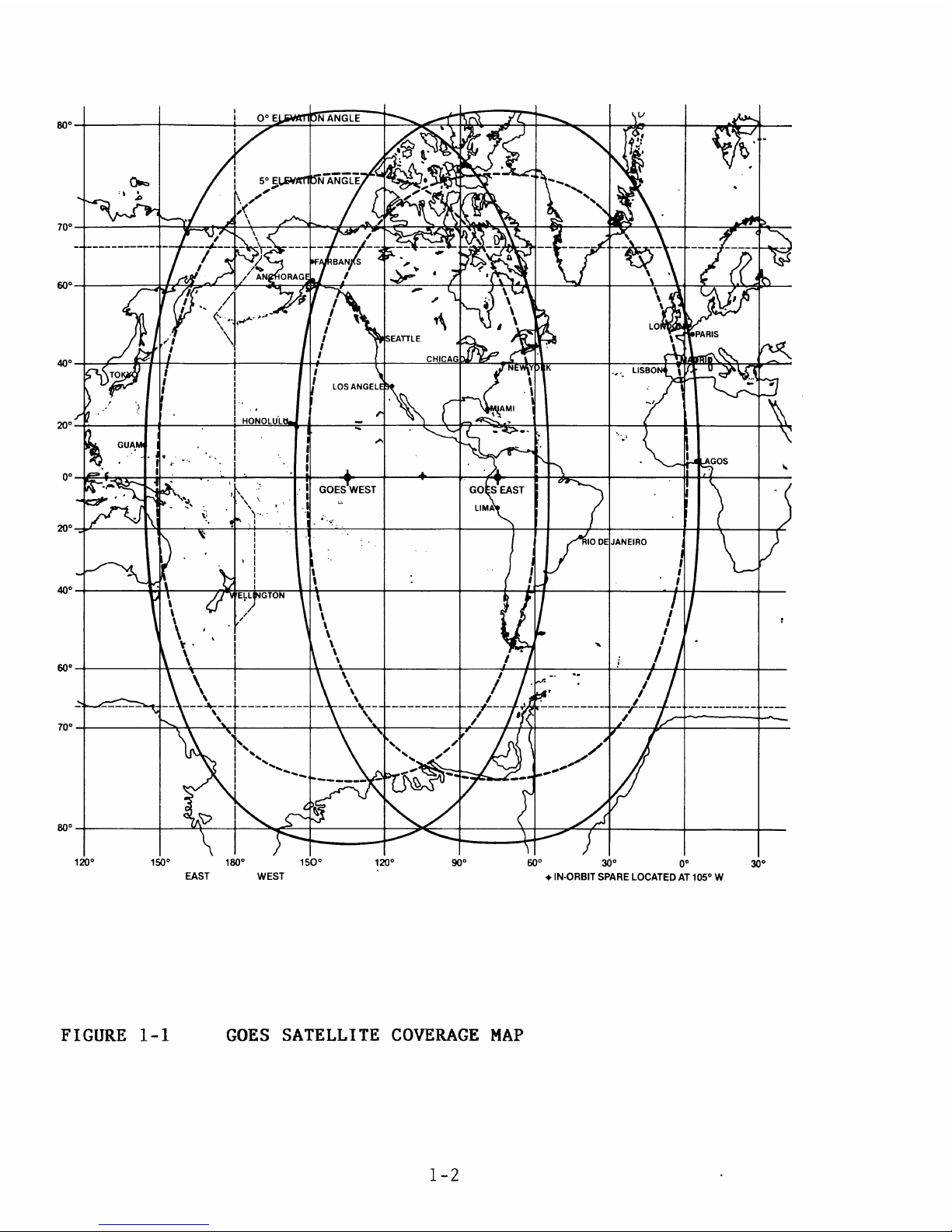
1-6
The Model 468-DC
Satellite
Svnchronized
Dis:dtal
Clock.
when
using
the
A-468MS
Antenna,
is
gu~ranteed
to
op~rate
~t
any
location
within
the
5°
viewing
angle
of
the
satellite
as
shown
on
the
map
enclosed.
For
viewing
angles
of
0°
- 5°
the
Model
468-HX
should
be
utilized.
1-1
Page 15
150° 180°
150°
120°
900
~o ~o
~
EAST WEST
+ IN-ORBIT
SPARE
LOCATED
AT
105° W
FIGURE
1-1
GOES
SATELLITE
COVERAGE
MAP
1-2
Page 16
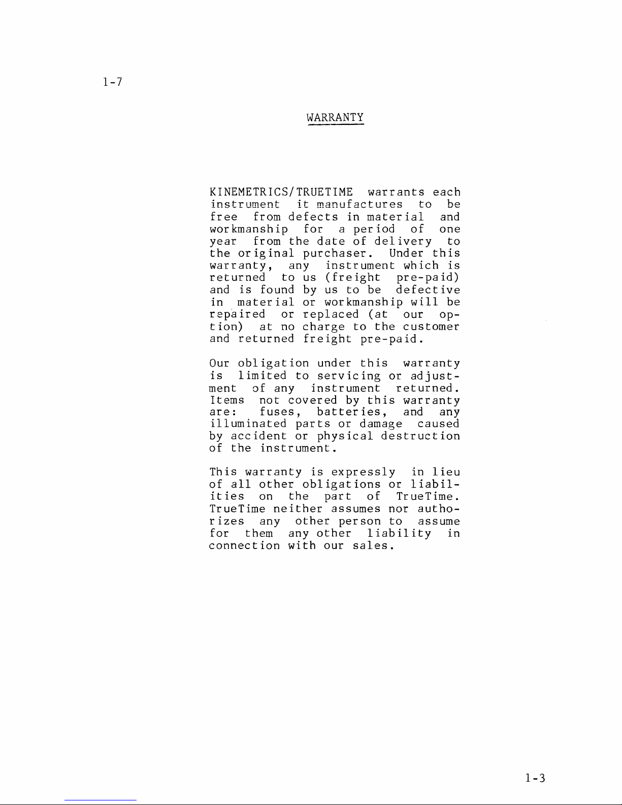
1-7
WARRANTY
KINEMETRICS/TRUETIME
warrants
each
instrument
it
manufactures
to
be
free
from
defects
in
material
and
workmanship
for
a
period
of
one
year
from
the
date
of
delivery
to
the
original
purchaser.
Under
this
warranty,
any
instrument
which
is
returned
to
us
(freight
pre-paid)
and
is
found
by
us
to
be
defective
in
material
or
workmanship
will
be
repaired
or
replaced
(at
our op-
tion)
at
no
charge
to
the
customer
and
returned
freight
pre-paid.
Our
obligation
under
this
warranty
is
limited
to
servicing
or
adjust-
ment
of
any
instrument
returned.
Items
not
covered
by
this
warranty
are:
fuses,
batteries,
and
any
illuminated
parts
or
damage
caused
by
accident
or
physical
destruction
of
the
instrument.
This
warranty
is
expressly
in
lieu
of
all
other
obligations
or
liabil-
ities
on
the
part
of
TrueTime.
TrueTime
neither
assumes
nor
autho-
rizes
any
other
person
to
assume
for
them
any
other
liability
in
connection
with
our
sales.
1-3
Page 17
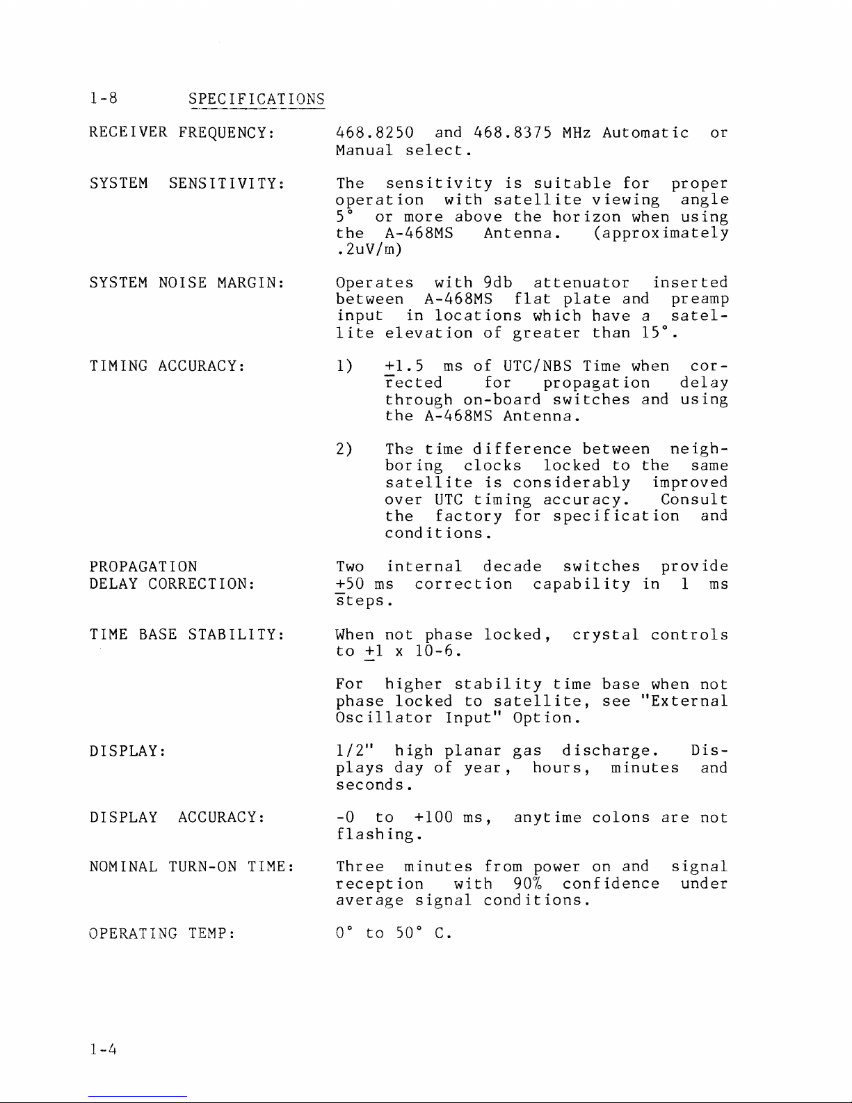
1-8
SPECIFICATIONS
RECEIVER
FREQUENCY:
SYSTEM
SENSITIVITY:
SYSTEM
NOISE
MARGIN:
TIMING
ACCURACY:
PROPAGATION
DELAY
CORRECTION:
TIME
BASE
STABILITY:
DISPLAY:
DISPLAY
ACCURACY:
NOMINAL
TURN-ON
TIME:
OPERATING
TEMP:
1-4
468.8250
and
468.8375
MHz
Automatic
or
Manual
select.
The
sensitivity
is
suitable
for
proper
operation
with
satellite
viewing
angle
5°
or
more
above
the
horizon
when
using
the
A-468MS
Antenna.
(approximately
.2uV/m)
Operates
with
9db
attenuator
inserted
between
A-468MS
flat
plate
and
preamp
input
in
locations
which
have
a
satel-
lite
elevation
of
greater
than
15°.
1)
+1.5
ms
of
UTC/NBS
Time when
cor-
rected
for
propagation
delay
through
on-board
switches
and
using
the
A-468MS
Antenna.
2) The
time
difference
between
neigh-
boring
clocks
locked
to
the
same
satellite
is
considerably
improved
over
UTC
timing
accuracy.
Consult
the
factory
for
specification
and
conditions.
Two
internal
decade
switches
provide
+50
ms
correction
capability
in
1
ms
steps.
When
not
phase
locked,
crystal
controls
to
+l
x
10-6.
For
higher
stability
time
base
when
not
phase
locked
to
satellite,
see
"External
Oscillator
Input"
Option.
1/2"
high
planar
gas
discharge.
plays
day
of
year,
hours,
minutes
seconds.
Dis-
and
-0
to
+100
ms,
anytime
colons
are
not
flashing.
Three
minutes
from power on and
reception
with
90%
confidence
average
signal
conditions.
0°
to
50°
C.
signal
under
Page 18
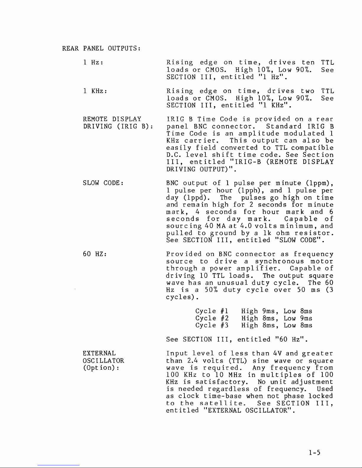
REAR
PANEL
OUTPUTS:
1 Hz:
KHz:
1
DRM()'l'R
.l\..LU:J
\J
..L
.U
DRIVING
SLOW
CODE:
f\T
~
LI.LU
(IRIG
DT
L.
.UC:J.
AV
.&..
B):
Rising
loads
SECTION
Rising
loads
SECTION
or
or
edge
CMOS.
III,
edge
CMOS.
III,
IRIG B Time
panel
Time
KHz
easily
D.C.
III,
DRIVING
BNC
1
pulse
day
and
mark,
seconds
sourcing
pulled
See
BNC
Code
carrier.
field
level
entitled
OUTPUT)".
output
per
(lppd).
remain
4
seconds
for
40
to
SECTION
on
time,
High
entitled
on
time,
High
entitled
Code
connector.
is
an
amplitude
This
converted
shift
time
"IRIG-B
of
1
pulse
hour
(lpph),
The
high
for
day
MA
at
4.0
ground
III,
entitled
10%,
"l
10%,
"l
is
provided
Standard
output
to
code.
(REMOTE
per
pulses
2
seconds
for
hour
mark.
volts
by a lk
drives
Low
Hz".
drives
Low
KHz".
modulated
can
TTL
See
minute
and 1
go
high
mark
Capable
minimum,
ohm
"SLOW
ten
90%.
two
90%.
on
a
TTL
See
TTL
See
rear
IRIG B
also
be
compatible
Section
DISPLAY
(lppm),
pulse
on
for
per
time
minute
and
of
and
resistor.
CODE".
1
6
60
HZ:
EXTERNAL
OSCILLATOR
(Option):
Provided
source
through
driving
wave
Hz
has
is
cycles).
See
SECTION
Input
than
wave
100
KHz
is
as
to
level
2.4
is
KHz
is
needed
clock
the
entitled
on
BNC
connector
to
drive
a
power
10
an
a
50%
Cycle
Cycle
Cycle
TTL
unusual
amplifier..
loads.
duty
#1
#2
#3
III,
of
less
volts
(TTL)
required.
to
10
MHz
satisfactory.
regardless
time-base
satellite~
"EXTERNAL
a
synchronous
The
duty
cycle
cycle.
over
High 9ms,
High 8ms,
High 8ms,
entitled
than
sine
Any
in
of
when
4V
wave
frequency
multiples
No
unit
frequency.
not
See
OSCILLATOR".
as
frequency
Capable
output
50
Low
8ms
Low
9ms
Low
8ms
"60
Hz".
and
greater
or
adjustment
phase
SECTION
motor
of
square
The 60
ms
(3
square
from
of
100
Used
locked
III.
.
1-5
Page 19
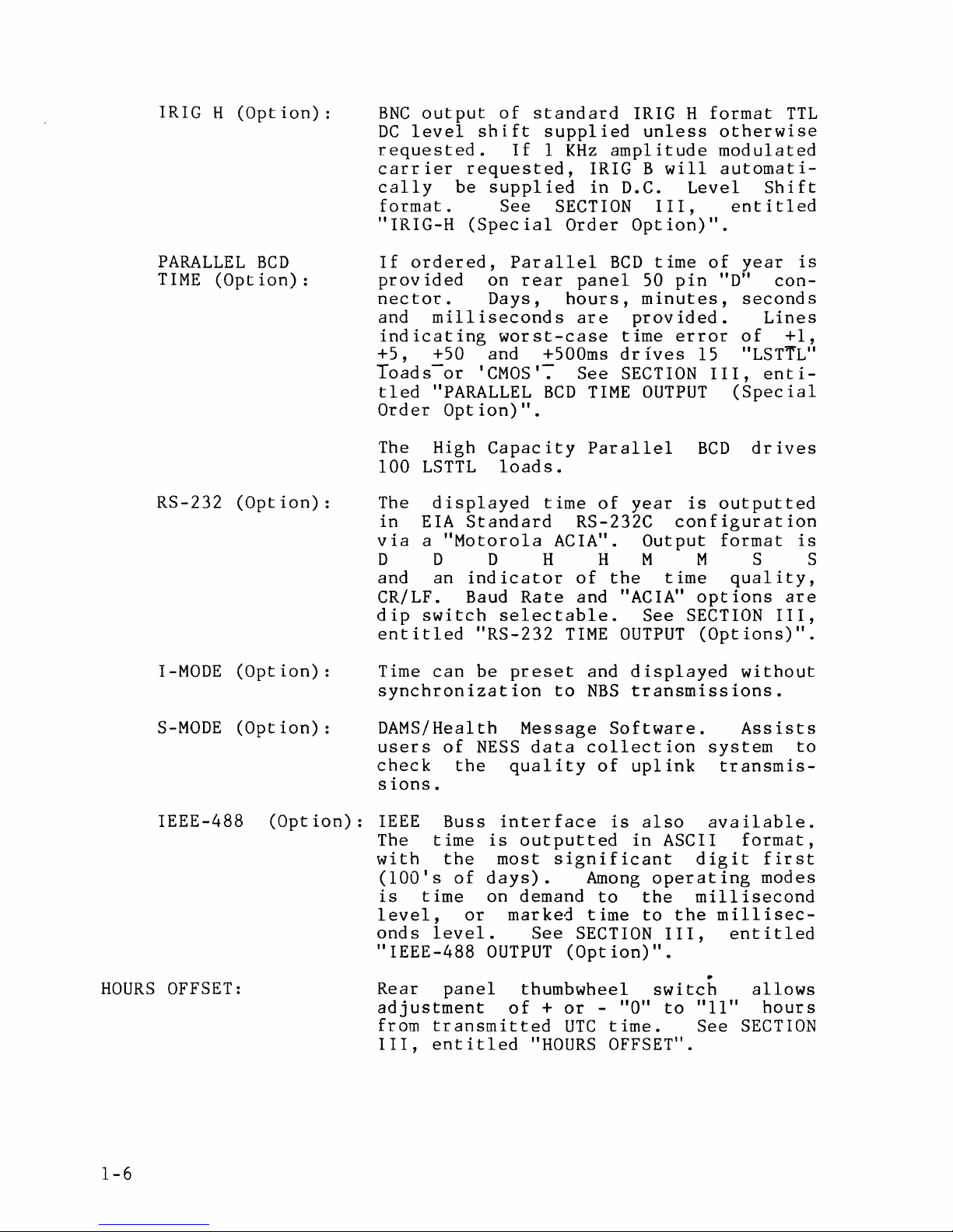
IRIG H
(Option):
PARALLEL
BCD
TIME
(Option):
RS-232
(Option):
I-MODE
(Option):
S-MODE
(Option):
BNC
output
of
standard
IRIG H
format
TTL
DC
level
shift
supplied
unless
otherwise
requested.
If
1
KHz
amplitude
modulated
carrier
requested,
IRIG B
will
automati-
cally
be
supplied
in
D.C.
Level
Shift
format.
See
SECTION
III,
entitled
"IRIG-H
(Special
Order
Option)".
If
ordered,
Parallel
BCD
time
of
year
is
provided
on
rear
panel
50
pin
"D"
con-
nector.
Days,
hours,
minutes,
seconds
and
milliseconds
are
provided.
Lines
indicating
worst-case
time
error
of
+l,
+5,
+50 and +500ms
drives
15
"LST'T"L"
Toads-or
'CMOS': See
SECTION
III,
enti-
tled
"PARALLEL
BCD
TIME
OUTPUT
(Special
Order
Option)".
The High
Capacity
Parallel
BCD
drives
100
LSTTL
loads.
The
displayed
time
of
year
is
outputted
in
EIA
Standard
RS-232C
configuration
via
a
"Motorola
ACIA".
Output
format
is
D D D H H M M S S
and an
indicator
of
the
time
quality,
CR/LF. Baud
Rate
and "ACIA"
opt
ions
are
dip
switch
selectable.
See
SECTION
III,
entitled
"RS-232
TIME
OUTPUT
(Options)".
Time
can
be
preset
and
displayed
without
synchronization
to
NBS
transmissions.
DAMS/Health Message
Software.
Assists
users
of
NESS
data
collection
system
to
check
the
quality
of
uplink
transmis-
sions.
IEEE-488
(Option):
IEEE
Buss
interface
is
also
available.
HOURS
OFFSET:
1-6
The
time
is
outputted
in
ASCII
format,
with
the
most
significant
digit
first
(lOO's
of
days).
Among
operating
modes
is
time
on demand
to
the
millisecond
level,
or
marked
time
to
the
millisec-
onds
level.
See
SECTION
III,
entitled
"IEEE-488
OUTPUT
(Option)".
•
Rear
panel
thumbwheel
switch
allows
adjustment
of
+
or
- "O"
to
"11"
hours
from
transmitted
UTC
time.
See
SECTION
III,
entitled
"HOURS
OFFSET
11
•
Page 20
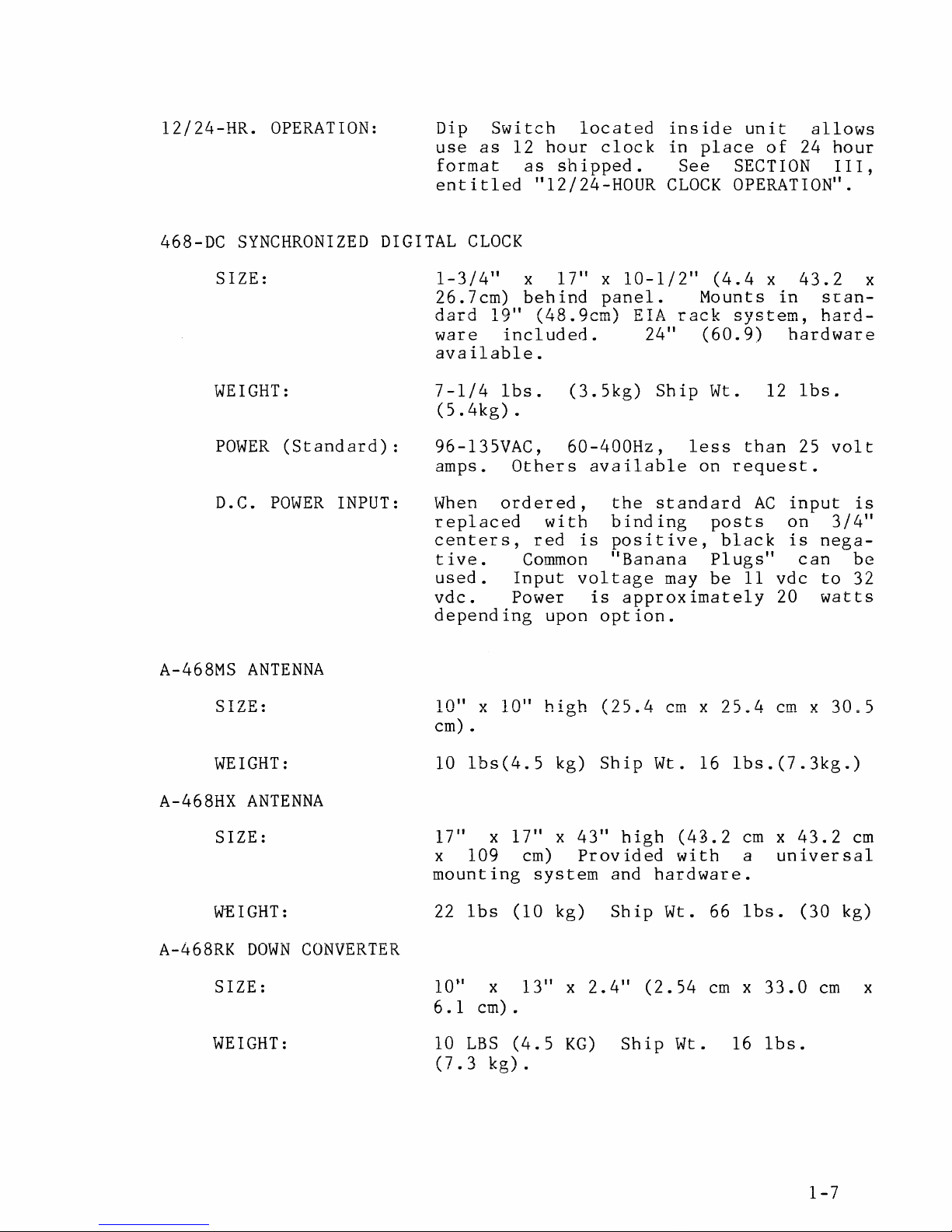
12/24-HR.
OPERATION:
Dip
use
Switch
as
format
entitled
located
12
hour
as
clock
shipped.
"12/24-HOUR
inside
in
place
See
CLOCK
unit
SECTION
of
allows
24
hour
III,
OPERATION".
468-DC
SIZE:
WEIGHT:
POWER
D.C.
A-468MS
SYNCHRONIZED
(Standard):
POWER
INPUT:
ANTENNA
DIGITAL
1-3/4"
26.7cm)
dard
ware
available.
7-1/4
(5.4kg).
96-135VAC,
amps.
When
replaced
centers,
tive.
used.
vdc.
depending
CLOCK
19"
included.
lbs.
Others
ordered,
Input
Power
x
17" x 10-1/2"
behind
panel.
(48.9cm)
(3.5kg)
60-400Hz,
available
with
red
Common
binding
is
"Banana
voltage
is
upon
option.
(4.4
Mounts
EIA
rack
24"
Ship
(60.
Wt. 12
less
on
the
standard
posts
positive,
Plugs"
may
be
approximately
x
system,
9)
than
request.
AC
black
11
43.2
in
stanhard-
hardware
lbs.
25
volt
input
on
3/4"
is
nega-
can
vdc
to
20
watts
x
is
be
32
CT7"R.
u.Lu:J.J•
WEIGHT:
A-468HX
SIZE:
WEIGHT:
A-468RK
SIZE:
WEIGHT:
ANTENNA
DOWN
CONVERTER
x
l 0
10"
cm).
10
lbs(4.5
17"
x
x 109
mounting
22
lbs
10
..
x
6.
1
cm)
10
LBS
(7
1.
...,,,
lro'i
..
~b
' , •
hi
oh
II
••
~b
..
kg)
Ship
17" x 43"
cm)
Provided
system
(10
kg)
13"
x
2.4"
.
(4.5
,/ •
KG)
(25.4
high
and
Ship
Ship
cm x
Wt. 16
(4'.1.2
with
hardware.
Wt. 66
(2.54
cm x 33.0
Wt. 16
25
..
4 cm x
lbs.(7.3kg.)
cm x 43.2
a
universal
lbs.
(30
lbs.
30.5
cm
cm
kg)
x
1-7
Page 21
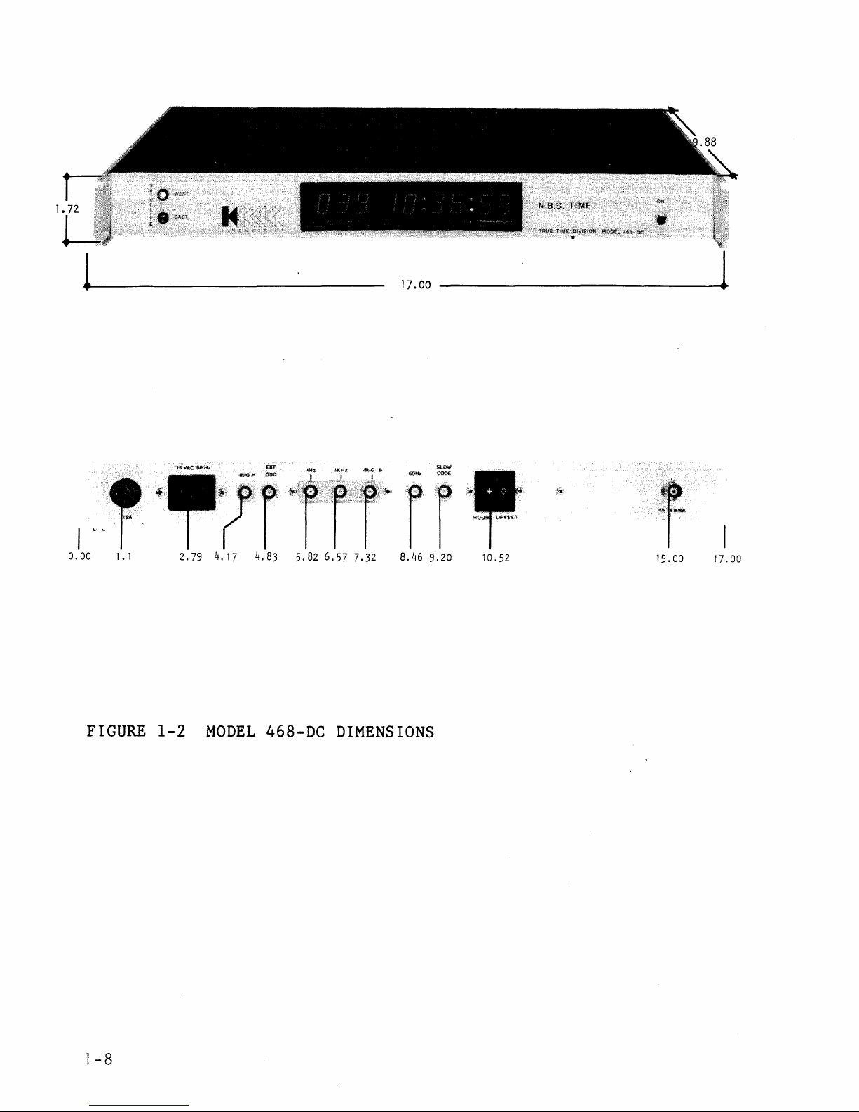
17.00
---------------·
15.00
17.00
FIGURE
1-2
MODEL
468-DC
DIMENSIONS
1-8
Page 22
SECTION
II
INSTALLATION
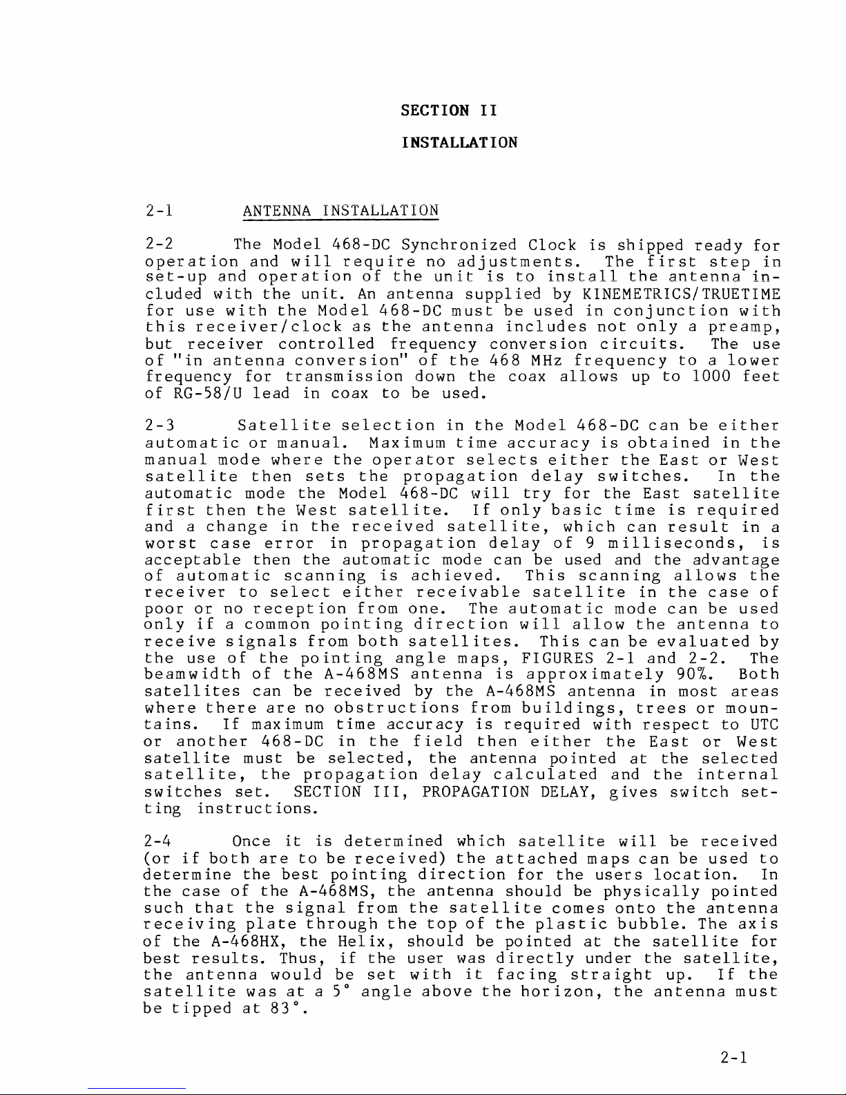
2-1
ANTENNA
INSTALLATION
2-2
The Model 468-DC
Synchronized
Clock
is
shipped
ready
for
operation
and
will
require
no
adjustments.
The
first
step
in
set-up
and
operation
of
the
unit
is
to
install
the
antenna
in-
cluded
with
the
unit.
An
antenna
supplied
by
KINEMETRICS/TRUETIME
for
use
with
the
Model
468-DC
must
be
used
in
conjunction
with
this
receiver/clock
as
the
antenna
includes
not
only
a
preamp,
but
receiver
controlled
frequency
conversion
circuits.
The
use
of
"in
antenna
conversion"
of
the
468
MHz
frequency
to a lower
frequency
for
transmission
down
the
coax
allows
up
to
1000
feet
of
RG-58/U
lead
in
coax
to
be
used.
2-3
Satellite
selection
in
the
Model
468-DC
can
be
either
automatic
or
manual.
Maximum
time
accuracy
is
obtained
in
the
manual
mode
where
the
operator
selects
either
the
East
or
West
satellite
then
sets
the
propagation
delay
switches.
In
the
automatic
mode
the
Model 468-DC
will
try
for
the
East
satellite
first
then
the
West
satellite.
If
only
basic
time
is
required
and
a
change
in
the
received
satellite,
which
can
result
in
a
worst
case
error
in
propagation
delay
of
9
milliseconds,
is
acceptable
then
the
automatic
mode
can
be
used
and
the
advantage
of
automatic
scanning
is
achieved.
This
scanning
allows
the
receiver
to
select
either
receivable
satellite
in
the
case
of
poor
or
no
reception
from
one.
The
automatic
mode
can
be
used
only
if
a
common
pointing
direction
will
allow
the
antenna
to
receive
signals
from
both
satellites.
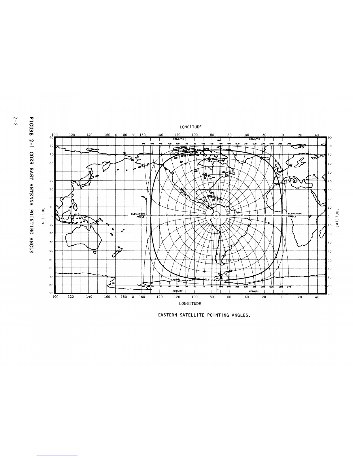
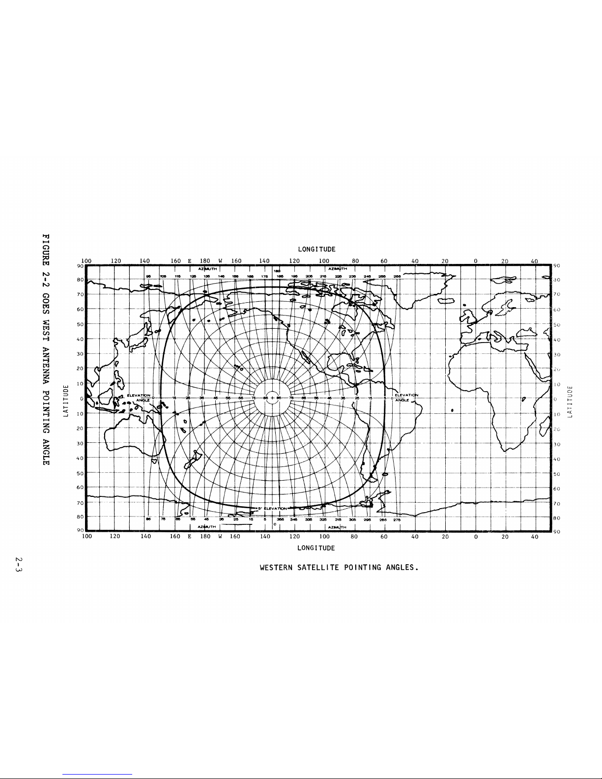
This
can
be
evaluated
by
the
use
of
the
pointing
angle
maps,
FIGURES
2-1
and
2-2.
The
beamwidth
of
the
A-468MS
antenna
is
approximately
90%.
Both
satellites
can
be
received
by
the
A-468MS
antenna
in
most
areas
where
there
are
no
obstructions
from
buildings,
trees
or
moun-
tains.
If
maximum
time
accuracy
is
required
with
respect
to
UTC
or
another
468-DC
in
the
field
then
either
the
East
or
West
satellite
must
be
selected,
the
antenna
pointed
at
the
selected
satellite,
the
propagation
delay
calculated
and
the
internal
switches
set.
SECTION
III,
PROPAGATION
DELAY,
gives
switch
set-
t i ng
instr
u c t
ions.
2-4
Once
it
is
determined
which
satellite
will
be
received
(or
if
both
are
to
be
received)
the
attached
maps
can
be
used
to
determine
the
best
pointing
direction
for
the
users
location.
In
the
case
of
the
A-468MS,
the
antenna
should
be
physically
pointed
such
that
the
signal
from
the
satellite
comes
onto
the
antenna
receiving
plate
through
the
top
of
the
plastic
bubble.
The
axis
of
the
A-468HX.
the
Helix,
should
be
pointed
at
the
satellite
for
best
results.
Thus,
if
the
user
was
d~irectly
under
the
satellite,
the
antenna
would
be
set
with
it
facing
straight
up.
If
the
satellite
was
at
a 5°
angle
above
the
horizon,
the
antenna
must
be
tipped
at
83°.
2-1
Page 23
N
'"1'.I
I
II-«
N
Cl
LONGITUDE
c::
~
tl;l
100 120 140 160
E 180
w
160
140 120 100
80 60 40 20
0 20
40
90
.-.z
TH
.-.z
H
90
~
I
,......
80
80
0
70
70
0
pj
(/)
60
60
t:zj
>
50
50
{/)
-1
40
40
>
z
30
30
t-i
t:zj
z
20
20
z
>
w
10
10
w
l'l:J
Cl
Cl
0
:::i
=>
1-4
~--
0
0
.....
z
I-
.....
1--J
c:(
10
10
<(
t-4
_J
....J
z
0
?O
20
>
z
30
30
0
t""4
40
40
1:11
50
50
60
60
lO
70
80
80
AZ
H
90
90
100
120 140
160
E 180 w 160
140 120
100 80
60
t~O
20
0 20
40
LONGITUDE
EASTERN
SATELLITE
POINTING
ANGLES.
Page 24
N
1
l;..)
N
I
N
0
0
~
en
w
Cl
::::>
II-
c:(
.....J
LONGITUDE
100
120
140 160 E
180
W
160
140 120
100
80
60
40
20 0
9
0.-
..
,_.~,._
......
..mi
.......................
A.Z
....
TH
..........................................
A.Z
.... H ..
.,.
.............
.,.
...........................
-~_.llliilp
.........
....,
.....
S'O
80
70
60
50
40
30
20
10
20
30
40
50
60
70
80
AZ
TH
dO
70
to
40
.30
10
Lu
C..J
::::>
0
1--
l·-
1 ()
~:5
30
AZ
H
90._
..........
-.
...........
-.
....................................
._
...
._
..
._
......... .-... .-... .-.. .-........ .-........
_..
...
11111111
...
...i.
...
...i.-.._.
..
_...
...
_...
.......
_.
90
100
120
140
160
E
180 W 160
140
120
100
80
60
40
20
0
20
40
LONGITUDE
WESTERN
SATELLITE
POINTING
ANGLES.
Page 25
2-5
Included
with
the
antenna
is
a
mounting
flange
with
a
shaft
attached
to
allow
versatile
tipping
as
well
as
rotation
for
proper
antenna
pointing.
The
stand
also
allows
attachment
of
this
antenna
to
a
flat
surface
for
mounting.
See
Section
VII.
2-6
Once
the
mounting
and
pointing
of
the
antenna
is
com-
plete,
attach
a
lead
in
coax.
For
this
purpose
RG-58/U
is
avail-
able
from
Kinemetrics/Truetime
in
50'
and
100'
lengths.
2-7
RACK
MOUNTING
2-8
If
it
is
desired
to
mount
the
Model 468-DC
in
a
stan-
dard
19"
rack
system,
use
the
rack
mounting
ears
provided
with
the
unit.
These
ears
may
be
attached
to
the
side
of
the
cabinet
~y
removing
the
two
8-32
flat
head
screws
on
the
side
of
the
instrument
and
placing
the
screws
through
the
counter-sunk
hole
in
the
bracket
and
re-installing
the
screw.
The
unit
now
may
be
mounted
in
a
1-3/4"
opening
in
any
EIA
standard
19"
rack
system.
2-9
INSTRUMENT
START-UP
2-10
After
the
antenna
installation
is
complete,
as
de-
scribed
in
SECTION
II,
entitled
"Antenna
Installation"
above,
the
lead-in
coax
should
be
connected
to
the
rear
panel
BNC
connector
labeled
"ANTENNA".
Connect
the
power
cord
to
the
socket
on
the
rear
panel
and
plug
the
unit
into
an
appropriate
power
source.
The power
switch
on
the
front
panel
may
now
be
turned
on.
2-11
When
the
power
is
turned
on,
the
initial
indication
of
proper
operation
of
the
Model 468-DC
is
the
colons
on
the
display.
The
colons
will
blink
off
and on
at
about
once
per
second.
This
indicates
to
the
user
that
the
unit
is
operating
properly
and
that
the
receiver
is
looking
for
phase
lock
to
the
carrier
of
the
signql
and
then
to
the
100
Hz
data
rate
of
the
information
broadcast.
Next,
after
the
468-DC
has
read
and
recognized
the
maximum
length
sequence
(MLS)
transmitted
each
1/2
second,
the
colons
will
be
locked
on
solid.
2-12
Following
this
data
lock,
the
synchronized
clock
will
recognize
that
it
is
reading
data,
a
satellite
location
(as
transmitted
in
the
message)
will
be
read.
From
this
information,
the
468-DC
can
determine
if
it
is
locked
to
the
"EAST"
OR
"WEST"
Satellite
and 1
ight
the
appropriate
"LED" on
the
front
panel.
2-13
Finally,
after
two 30
second
long
time
frames
of
infor-
mation
of
the
time
of
year
have
been
read
which
agree
as
to
the
time,
the
front
panel
display
will
light
indicating
the
correct
time
of
year.
At
this
same
time,
any
options
which
have
been
ordered
to
electrically
output
the
time
will
begin
to
function.
2-14
One
of
the
most
often
overlooked
and
yet
most
important
factors
in
the
installation
and
operation
of
the
Model 468-DC
is
proper
antenna
installation.
Without
a
proper
antenna
installation,
the
signal
from
the
satellite
will
not
be
received
and
thus
the
unit
cannot
possibly
function
properly.
In
many
2-4
Page 26

case
s
11
j us t
to
tr
y
it
out
11
, an
at
tempt
w i 11
be
mad e to
ope r ate
the
unit
with
the
antenna
inside
a
building
or
without
determining
the
proper
antenna
pointing
angle.
This,
as
often
as
not,
results
in
inability
to
lock
to
the
satellite
signal,
and
failure
to
decode
the
time.
2-5
Page 27

3-1
INTRODUCTION
SECTION
III
OPERATION
3-2
The
Model
468-DC
Synchronized
Clock
provides
the
user
with
a
means
of
obtaining
time
traceable
to
the
U.S.
National
Bureau
of
Standards
with
an
accuracy
of
+L5msy
For
stability,
the
time
base
is
phase-locked
to
the
satellite
data
rate.
The
time-of-year
information
broadcast
by
The
National
Oceanic
and
Atmospheric
Administration
through
the 11GOES
11
Satellite
is
dis-
played
in
days,
hours,
minutes
and
seconds
on
the
front
pan~l.
Also
available
are
outputs
of
this
time
information
in
the
form
of
Remote
Display
Driving
Output
(IRIG-B,
Parallel
BCD
Time,
or
RS-232C
compatible
interface,
or
IEEE-488
compatibility).
The
Model 468-DC
has
been
specifically
designed
to
minimize
operator
set-up
and
will
provide
many
years
of
service
without
attention.
3-3
SATELLITE
EAST-WEST
LED
3-4
Located
on
the
lower
left
hand
corner
of
the
front
panel
are
two LED's
labeled
"Satellite",
"WEST"
or
"EAST".
These
green
LEDs
will
light
anytime
the
unit
is
receiving
a
sufficient
signal
from
one
of
the
satellites
to
allow
the
internal
time
base
to
phase
lock
to
data
frequency
of
100
Hz. When
the
unit
is
initially
turned
on,
if
adequate
signal
is
present,
this
LED
will
light
within
30
to
45
seconds.
If,
during
the
course
of
opera-
tion,
phase
lock
with
the
satellite
is
lost
long
enough
for
the
R.F.
Circuits
to
sweep
for
phase
lock,
(about
150
seconds),
this
light
will
go
out.
When
phase
lock
is
regained
and a satellite
position
is
recognized
in
the
data,
the
appropriate
LED
will
again 1 ight.
3-5
Phase
lock
will
be
maintained
continually
in
most
areas
and
the
only
occasion
for
loss
of
lock
will
be
experienced
due
to
local
noise
interference.
The
most
common
source
is
"land
mobile"
transmitters
on
a
frequency
of
468.8250
MHz
which
is
directly
on
the
Western
Satellite
frequency.
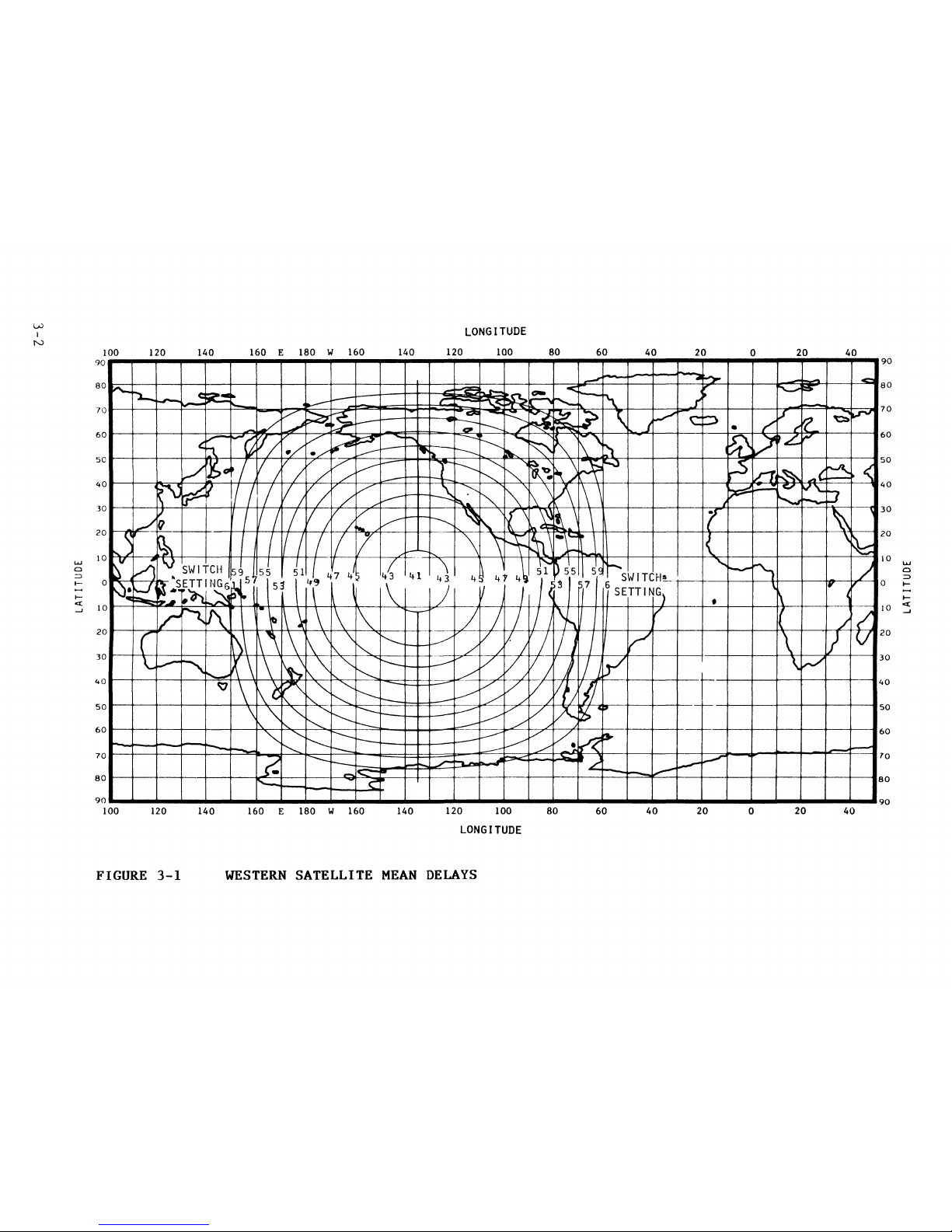
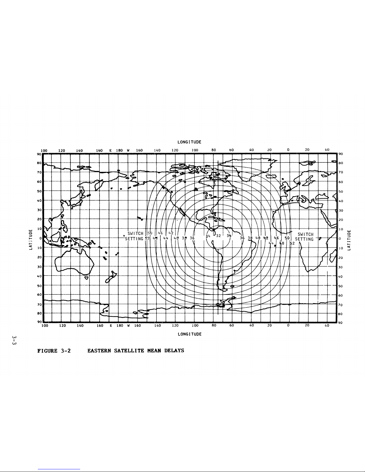
3-6
The
Satellite
LED
also
provides
information
as
to
the
Satellite
position.
If
the
468-DC
is
able
to
read
the
time
of
ye
a r
in
for
m a t
ion
b u t t
he
s a t e
11
i t e po s i t i
on
in
form
a t i o nr e ad
in
code
does
not
agree
with
the
position
shown
on
the
propagation
determination
maps,
(FIGURES
3-1
and
3-2),
the
LED
will
blink.
If
the
R.
F.
carrier
on
which
the
time
data
was
found
is
on
the
468.8250
MHz
frequency,
the
West
LED
will
blink,
if
on
468.8375
MHz,
the
East
LED
will
blink.
This
indicates
to
the
user
which
S3tellite
is
being
received,
but
that
propagation
delay
informa-
tion
may
be
incorrect
and
exact
satellite
position
should
be
determined
if
accuracies
to
the
millisecond
level
are
desired.
Satellite
LED
blinking
also
occurs
when
the
unit
is
in
"Auto-
matic"
satellite
selection,
the
468-DC
has
swept
to
the
other
3-1
Page 28
L.U
I
N
w
Cl
:::>
tt-
c:(
_J
LONGITUDE
100 120 140
160
E 180 W 160 140 120 100 80
60
40
20
0
20
40
90
...........................................................................................................................................................................
.,.
..........
90
50
20
10
w
Cl
::::>
0
I-
l-
*---l+---+-~-+--fll~-++--+--++~~~+-+--4f---+~-+-~-+-~~~+--~t----1'-~--
1 o
:3
20
50
90
...........................................................................................
1111111111
...................................................................................
90
100 120
140
160 E 180 W 160 140
120
100 80
60
40
20
0
20 40
LONGITUDE
FIGURE
3-1
WESTERN
SATELLITE
MEAN
DELAYS
Page 29
VJ
I
VJ
LaJ
0
:::;:)
II-
c(
....J
LONGITUDE
100
120
140
160 E 180 W 160
JL40
120
100
80
bO
40
0 20
40
90
.......................
--i,_.
......
..,.
................
,...
........................................................
,...
.............................. ~ ..................
l
.....................
~.90
80
60
50
40
10
40
10
LaJ
0
:::;:)
0
I-
40
50
60
90
.........................................................................................................................................................
l
.............................................
90
100
120
140
160 E 180 W 160 140 120 100 80 60 40 20 0 20 40
LONGITUDE
FIGURE
3-2
EASTERN
SATELLITE
MEAN
DELAYS
Page 30
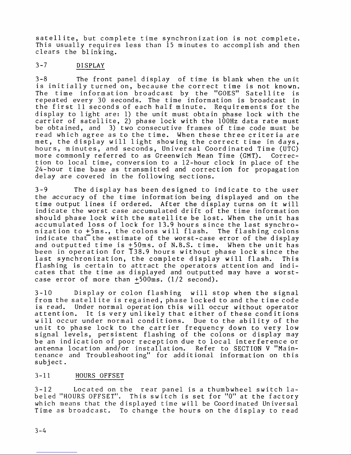
satellite,
but
complete
time
synchronization
is
not
complete.
This
usually
requires
less
than
15
minutes
to
accomplish
and
then
clears
the
blinking.
3-7
DISPLAY
3-8
The
front
panel
display
of
time
is
blank
when
the
unit
is
initially
turned
on,
because
the
correct
time
is
not
known.
The
time
information
broadcast
by
the
"GOES"
Satellite
is
repeated
every
30
seconds.
The
time
in
format
ion
is
broadcast
in
the
first
11
seconds
of
each
half
minute.
Requirements
for
the
display
to
light
are:
1)
the
unit
must
obtain
phase
lock
with
the
carrier
of
satellite,
2)
phase
lock
with
the
lOOHz
data
rate
must
be
obtained,
and 3)
two
consecutive
frames
of
time
code
must
be
read
which
agree
as
to
the
time.
When
these
three
er
iter
ia
are
met,
the
display
will
light
showing
the
correct
time
in
days,
hours,
minutes,
and
seconds,
Universal
Coordinated
Time
(UTC)
more
commonly
referred
to
as
Greenwich
Mean Time
(GMT).
Correc-
t
ion
to
local
time,
conversion
to
a
12-hour
clock
in
place
of
the
24-hour
time
base
as
transmitted
and
correct
ion
for
propagation
delay
are
covered
in
the
following
sections.
3-9
The
display
has
been
designed
to
indicate
to
the
user
the
accuracy
of
the
time
information
being
displayed
and on
the
time
output
lines
if
ordered.
After
the
display
turns
on
it
will
indicate
the
worst
case
accumulated
drift
of
the
time
information
should
phase
lock
with
the
satellite
be
lost.
When
the
unit
has
accumulated
loss
of
lock
for
13.9
hours
since
the
last
synchro-
nization
to
+Sms.,
the
colons
will
flash.
The
flashing
colons
indicate
that-the
estimate
of
the
worst-case
error
of
the
display
and
outputted
time
is
+SOms.
of
N.8.S.
time.
When
the
unit
has
been
in
operation
for
T38.9
hours
without
phase
lock
since
the
last
synchronization,
the
complete
display
will
flash.
This
flashing
is
certain
to
attract
the
operators
attention
and
indi-
cates
that
the
time
as
displayed
and
outputted
may
have
a
worst-
case
error
of
more
than
~SOOms.
(1/2
second).
3-10
Display
or
colon
flashing
will
stop
when
the
signal
from
the
satellite
is
regained,
phase
locked
to
and
the
time
code
is
read.
Under
normal
operation
this
will
occur
without
operator
attention.
It
is
very
unlikely
that
either
of
these
conditions
will
occur
under
normal
conditions.
Due
to
the
ability
of
the
unit
to
phase
lock
to
the
carrier
frequency
down
to
very
low
signal
levels,
persistent
flashing
of
the
colons
or
di
splay
may
be
an
indication
of
poor
reception
due
to
local
interference
or
antenna
location
and/
or
installation.
Refer
to
SECTION V "Ma
in-
tenance
and
Troubleshooting"
for
additional
information
on
this
subject.
3-11
HOURS
OFFSET
3-12
Located
on
the
rear
panel
is
a
thumbwheel
switch
la-
beled
"HOURS
OFFSET".
This
switch
is
set
for
"O"
at
the
factory
which
means
that
the
displayed
time
will
be
Coordinated
Universal
Time
as
broadcast.
To
change
the
hours
on
the
display
to
read
3-4
Page 31

local
time,
set
the
switch
to
the
number
of
hours
your
location
is
offset
from
Greenwich,
England.
For
example,
if
you
·are
located
in
the
Eastern
Time
Zone
and
desire
to
display
Local
Standard
Time,
the
switch
should
be
set
for
"-5",
or
for
Daylight
Savings
Time
set
for
"-4".
If,
in
this
case,
the
display
was
indicatin~
1800
UTC.
the
clock
would
subtract
5
hours
and
display
1300
hour~
for
Locai
Standard
Time.
If
the
unit
has
electrically
outputted
time
(IRIG-B,
Parallel
BCD,
RS-232,
or
IEEE-488),
the
time
supplied
on
these
outputs
will
agree
with
the
display.
Additional
information
on
these
outputs
is
included
in
the
fol-
lowing
sect
ions.
3-13
12/24-HOUR
CLOCK
OPERATION
3-14
The
Model
468-DC
is
shipped
from
the
factory
for
opera-
tion
on
the
24-hour
clock
system
as
broadcast
by
the
National
Bureau
of
Standards.
If
it
is
desired
to
convert
the
clock
to
a
12-hour
clock
display,
a
small
internal
switch
can
be
turned.
3-15
To
convert
a
clock
to
the
12-hour
format
refer
to
FIGURE
3-3.
Remove
the
four
screws
retaining
the
lid
and
slide
the
select
switch
indicated
in
the
photograph
to
the
12-hour
position.
Replace
the
cover
and
re-install
the
screws.
3-16
AUTOMATIC/MANUAL
SATELLITE SELECTION
3-17
As
described
in
SECTION I
I,
"ANTENNA
INSTALLATION",
the
Model
468-DC
can
be
used
to
automatically
select
the
"EAST"
or
the
"WEST"
satellite,
or
can
be
set
manually
for
lock
to
either
s.atellite.
The
receiver,
as
shipped
from
the
factory,
is
set
for
"Automatic"
scanning
of
the
satellites.
If
it
is
desired
to
lock
the
receiver
onto
either
satellite,
remove
the
four
screws
retaining
the
lid.
By
referring
to
FIGURE
3-1,
locate
the
"EAST"
and
WEST"
Satellite
Switch.
If
it
is
desired
to
lock
to
the
East
Satellite,
turn
the
"EAST"
Switch
to
"ON",
if
the
'WEST"
Satel-
lite
is
desired,
turn
the
"WEST"
Switch
to
"ON".
With
both
switches
"OFF"
the
unit
will
be
returned
to
automatic
scanning
operation.
3-18
PROPAGATION
DELAY
3-19
This
feature
is
included
with
the
Model
468-DC
to
allow
the
microprocessor
to
compensate
for
the
delay
in
the
displayed
and
outputted
time
and
timing
marks
due
to
the
time
required
for
the
signal
to
travel
to
the
receiver
from
the
transmitter.
3-20
This
feature
consists
of
two
switches
on
the
Digital
Board
Assembly.
To
adjust
these
switches,
first
remove
the
four
screws
which
hold
the
top
cover
in
place,
remove
the
lid
and
set
it
aside.
Refer
to
FIGURE
3-3
for
identification
of
the
"Pro
pa-
n-
':l
t-
; n n
Tl
o 1
!:l
u
~
r.7 ;
t-
,-.
ho
c
11
'T'h
o
t-
r.7 n c r.7 ;
t-
,-.
ho
c ,-.
':l
n
ho
,-.
nm
h ; n o
r1
t-
f"\
f:,U\,...L.VL.1
V'-..L.UJ
LJH..L.\...'-LJ\..-JiJ
e
.LLJ'-
ll....VV\..J
..:JVY..L\....\,,...LJ'-...:J'
'-'-'Ll
LJ'-
'-'\Jl.J.11.J.LLJ.\,,...'-.&
'-'-'
provide
for
a
total
of
99
ms,
propagation
delay
for
the
unit.
The
switch
toward
the
rear
panel
provides
0
to
9
ms.
and
the
switch
toward
the
front
adds
to
this
in
steps
of
ten
from
0
to
90
m
s.
The
r e
for
e , i f i t i s
des
i r
ed
to
com
pens
a t e
for
5 9 ms .
prop
a -
3-5
Page 32

l"rj
v.::i
""""
'
O"
~
Vo)
'
Vo)
Pd
~
~
C/'l
b
n
~
""""
~
'3.
0
~
t:""'
~
CJ'<
~
'
d
n
BY
UNLOCK
1NDICATOR
(RED
LED)
100B.z
UNLOCK
1NDICATOlt
(RED
LED)
kJ.TERNAL
osc1LLATOR
· .ftl»ICATOll (
GlU!-1!.ll
lE1>)
nuc-»
TTL/
AH
sll.J.J!.CT
JIJMPI!.11.
pR.Ol'AGATION
DELAY
EAST
SATELLITE
SELECT
sw1TCR
WEST
SATELLITE
SELECT
sw1TCR
SLOW
coDE
OUTPUT
Page 33

gation
delay,
the
front
switch
would
be
turned
to
5
(for
50
ms)
and
the
rear
switch
to 9 (for
9
ms).
3-21
Through
the
ground
station
at
Wallops
Island,
the
Nat-
ional
Bureau
of
Standards
advances
the
time
sent
to
the
satellite
by
260.000
ms.
Propagation
delay
from
Wallops
Island
to
the
Satellite
and
back
to
earth
varies
between
242.50
and
271.50
ms.
depending
on
satellite
position
and
the
receiving
location.
This
results
in
the
receiver
signal
being
advanced
up
to
17.50
ms.
or
retarded
by
11.50
ms.
relative
to
UTC-NBS
depending
on
receiver
location
and
satellite
being
received.
3-22
This
offset
can
be
compensated
for
by
the
propagation
delay
switches
described
above.
A
switch
setting·
of
50
as
ship-
ped
from
the
factory,
sets
the
output
time
of
the
synchronized
c 1
oc
k s i mu 1
tan
eo
us
w i
th
the
r e c e
iv
ed t i me o f
the
s i g n a
1.
Inc r ea
s -
ing
the
propagation
delay
switch
setting
advances
the
output
time
relative
to
the
received
time
by
LO
ms.
per
step.
Thus,
a
switch
setting
of
62
advances
the
time
output
by
12
ms.
as
a
setting
of
32
on
the
switches
retards
the
output
time
by
18
ms.
3-23
The
appropriate
setting
of
the
propagation
delay
switches
can
be
determined
by
the
use
of
the
attached
maps,
FIGURES
3-1
and
3-2.
If
the
clock
is
locked
to
the
"EAST"
or
"WEST"
satellite
as
described
in
SECTION
III,
entitled
"AUTOMATIC/MANUAL
SATELLITE SELECTION",
the
delay
can
be
deter-
mined
relatively
accurately.
If
the
unit
is
left
on
the
"auto-
matic"
mode,
the
best
compromise
must
be
determined
depending
on
the
receiver
location.
3-24
EXAMPLE:
1)
A
user
located
in
the
southern
tip
of
Florida,
USA
and
having
his
unit
locked
to
the
"EAST"
satellite
should
set
the
switches
to
read
36
ms.,
"3''
on
the
lO's
of
milliseconds
switch
and
"6"
on
the
units
of
millisecond
switch.
2)
If
a
unit
is
located
at
120°
west
longitude
and
40°
north
latitude
and
left
in
"automatic"
mode,
the
switches
should
be
set
to
read
46
or
47
milli-
seconds
at
the
users
option.
This
would
be
ob-
tained
by
setting
the
lO's
of
milliseconds
switch
to 114"
and
the
units
switch
to
"6
11
or
"7".
1
HZ
3-25
The
1 Hz
is
provided
as
a
rear
panel
BNC
connector
and
can
be
used
for
a
wide
variety
of
timing
functions.
This
output
is
a
pulse
going
high
as
the
second
remains
high
for
100
milli-
seconds
and
going
low
for
the
remaining
900
milliseconds.
This
output
is
driven
from
a
2N3904
(Q3)
on
the
microprocessor
board
(Assembly
86-42,
see
SECTION V).
The
collector
of
Q3
is
pulled
up
to
+SVDC
with
a
3.3K
ohm
resistor.
This
output
is
taken
off
of
Pin
#3
of
Assembly
86-42
and
capable
of
driving
10
TTL
loads.
3-7
Page 34

3-26
1
KHz
3-27
The 1
KHz
rear
panel
output
is
similar
in
form
to
the
1
Hz
above.
It
is
a
square
wave
going
high
on
time,
remaining
high
for
100
microseconds
and
low
the
remaining
900
microseconds.
This
output
is
driven
by
U23
on
Assembly
86-74
(see
SECTION
V)
which
is a CMOS
part
number
4050.
This
output
is
fed
to
Assembly
86-42
in
interconnecting
wire(s)
and
to
the
rear
panel
from
86-42
Pin
Number
#17.
3-28
IRIG B
(REMOTE
DISPLAY
DRIVING
OUTPUT)
3-29
The
primary
purpose
of
the
IRIG-B
time
code
output
is
to
drive
slave
displays
manufactured
by
Kinemetrics/TrueTime.
This
output
consists
of
the
standard
IRIG-B
time
code.
Refer
to
SECTION
VIII
for
a
full
description
of
this
code.
3-30
When
using
this
code
for
other
than
driving
the
K
in
em
et
r i c s I Tr u e T i
me
Mod
e 1
RD
- B , i t
sh
o u 1 d
be
no
t e d
th
a t f o u r
"Control
Functions"
are
used.
These
control
functions
encode
estimated
time
accuracy
as
fully
described
in
SECTION
VII.
3-31
This
output
is
supplied
on a
rear
panel
BNC
connector.
When
shipped,
this
output
is
in
a 1
KHz
carrier
amplitude
modu-
lated
format
but
can
be
field
converted
to
D.C.
level
shift
code
format.
In
addition
to
driving
remote
displays,
this
output
can
be
used
to
synchronize
commercially
available
Time Code
Genera-
tors
or
direct
recording
on
magnetic
tape.
3-32
The
modulated
1
KHz
format
is a sine
wave
driven
by
two
sections
of
a
Texas
Instrument
Part
Number "TL084"
in
series
with
50 ohm
located
on
Assembly
86-74.
The
high
level
of
the
code
is
3.3
volt
peak
to
peak
+0.SV,
at
the
low
level
it
is
1
Volt
peak
to
peak
+.2V.
This
output
is
fed
to
Assembly
86-42
via
the
jumper
wire
(Pin
Number "P") and
to
the
rear
panel
from
terminal
number
18.
3-33
If
it
is
desired
to
convert
che
IRIG-B
time
code
from
the
amplitude
modulated
1
KHz
form
as
shipped,
to a level
shift
output,
it
is
necessary
to
remove
the
lid
and
move
one
wire.
To
remove
the 1 id,
take
out
the
four
screws
in
the
cover
and
set
the
lid
aside.
Locate
the
Analog
Board,
Assembly
86-74,
which
can
be
identified
with
the
assistance
of
the
photograph
in
FIGURE
3-3
of
this
manual.
3-34
After
locating
the
Analog
Board,
Assembly
86-74,
note
on
the
right
side
of
the
board
near
the
edge
a
red
jumper
wire
has
been
installed
in
two
of
three
holes
in
a
triangular
shape
pattern.
The
rear
point
to
which
the
wire
is
soldered,
labeled
"AM",
should
be
unsoldered
and swung
forward
and
resoldered
into
the
hold,
labeled
"TTL"
toward
the
front
of
the
instrument.
This
connects
the
lead
from
the
2N3904
transistor
near
this
hole
to
pin
"P"
of
the
edge
connector.
Replace
the 1 id
and
the
IRIG-B
output
will
now
be
in
level
shift
format.
3-35
The
Level
Shift
format
is
driven
by
QlOO
(2N3904)
on
3-8
Page 35

Assembly
86-74
with
2.2K ohm
pull
up
to
+SVDC.
This
will
dr
about
10
TTL
loads.
After
leaving
QlOO,
the
IRIG-B
is
transtc..
red
to
Assembly
86-42
on
jumper
wire
pin
"P"
and
to
the
rear
panel
connector
via
pin
18 on
thib
assembly.
3-36
SLOW
CODE
3-37
The
"Slow
Code"
output
from
the
Model
468-DC
has
been
provided
primarily
for
the
purpose
of
providing
timing
marks
on
drum
recorders
such
as
the
Kinemetrics/TrueTime
Model VR-1.
This
output
is
a
single
line
which
goes
high
once
per
minute.
un
minute
marks
the
output
remains
high
for
two
seconds,
on
hour
marks
the
line
is
held
high
for
four
seconds
and
for
the
day
mark,
a
six
second
high
is
provided.
3-38
This
output
is
driven
by
Ql on
Assembly
86-42.
This
is
a MPS3702
transistor
and
will
source
40
ma
at
4.0VDC.
This
drive
is
provided
fro:m
Pin
#2
on
the
Assembly
86-42
through
a
wire
to
the
rear
panel
BNC.
3-39
A
second
format
of
this
slow
code
is
provided
and
can
be
easily
field
converted.
If
the
wire
from
Pin
#2
of
Assembly
86-42
is
connected
to
Pin
#1
on
the
assembly,
the
complement
of
Pin
#2
described
above
is
provided
(see
FIGURE
3-3).
Pin
#1
output
is
driven
by
Q2
(2N3904)
with
approximately
6K
ohm
pull
up
to
SVDC.
This
will
drive
2
TTL
loads.
When
wired
in
this
man-
ner,
the
output
on
the
rear
panel
BNC
will
be
normally
high.
On
the
minute
it
will
go
low 2 seconds,
4
s'econds
on
the
hour
and
6
seconds
for
a
day
indicator.
3-40
NOTE:
If
"External
Oscillator"
Option
is
ordered
in
conjuncc1on
w1cn
Parallel-BCD,
RS-232
or
IEEE-488
Output
Options,
the
"Slow
Code"
Output
is
not
on a rear
panel
connector
but
the
user
is
free
to
lift
the
lid
and
obtain
this
output
from
Pin
#1
or
Pin
#2
of
Assembly
86-42
for
use.
3-41
60 Hz
3-42
The
precision
60 Hz
output
on
the
rear
panel
BNC,
like
the
Slow
Code,
has
been
provided
primarily
for
the
purpose
of
supplying
a known 60 Hz
signal
to
drive
synchronous
motors.
This
output,
when
supplied
through
a
power
amplifier
such
as
the
Kinemetrics
Model PA-1,
will
provide
a
constant
60 Hz
signal
for
driving
drum
recorders
independent
of
local
power
line
varia-
tions.
3-43
A
quasi-square
wave
is
provided
for
this
purpose
with
transitions
on
exact
milliseconds.
The
half
cycle
periods
are
8ms,
8ms,
9ms,
8ms, 8ms,
and
9ms;
etc.,
then
repeating
the
pat-
tern.
This
provides
exactly
a 60
Hz
square
wave
after
the
av-
erage
of
three
cycles.
3-44
Driven
by
U
11
on
Assembly
86-42
(74LSOO)
this
output
is
capable
of
driving
5
TTL
loads.
The
output
is
from
the
front
edge
of
Assembly
86-42
from
a
bifurcated
terminal
labeled
"60
3-9
Page 36

Hz",
through
a
wire
to
the
rear
panel
connector.
3-45
EXTERNAL
OSCILLATOR
(Option)
3-46
If
optionally
ordered,
this
rear
panel
input
provides
for
a
local
lab
standard
type
of
oscillator
to
be
utilized
as
a
clock
time
base
during
periods
when
phase
lock
with
the
satellite
is
lost.
3-47
The
input
frequency
for
this
option
may
be
anywhere
between
100
KHz
and 10
MHz
in
increments
of
100
KHz.
The
signal
can
be
a
sine
wave
or
square
wave
with
the
low
level
less
than
0.4V
and
the
peak
greater
than
2.4
(TTL).
This
input
is
pre-
sented
from
the
rear
panel
BNC
through
a
coax
to
the
input
of
U 1
(74LS74),
which
has
a
lOK
ohm
pull
up
to
+5VDC.
This
input
therefore
is
one
TTL
load.
3-48
Operationally,
any
time
the
Model
468-DC
is
unable
to
phase
lock
to
the
100
Hz
data
rate
from
the
satellite,
the
clock
time
base
will
utilize
the
provided
input
in
the
"External
Oscillator"
BNC
connector.
If
a
reference
frequency
is
not
provided
on
this
BNC,
the
468-DC
will
continue
to
operate
on
its
own
internal
crystal.
3-49
On
Assembly
86-74,
a
green
LED
has
been
provided
(see
FIGURE
3-3)
to
show
the
user
that
the
468-DC
recognizes
the
presence
of
his
External
Oscillator.
If
the
LED
is
not
lit,
the
unit
does
not
recognize
the
input
signal
and
further
investigation
will
be
necessary
for
proper
operation
of
this
option.
3-50
When
the
situation
arises
that
lock
to
the
satellite
is
lost,
even
if
a
cesium
oscillator
is
used
for
the
External
Oscil-
lator,
the
indications
of
time
drift
continue.
Therefore,
the
colons
on
the
display
and
whole
display
will
blank
and
flash
in
the
usual
manner
to
indicate
loss
of
satellite
reception
even
in
case
of a "perfect"
external
time
base.
The
output
time
error
message
in
IRIG-B,
Parallel
BCD,
RS-232
and
IEEE-488
also
func-
tion
to
indicate
loss
of
accuracy.
3-51
IRIG H
(Option)
3-52
When
ordered,
IRIG
His
provided
on a rear
panel
BNC.
If
this
is
ordered
in
conjunction
with
Parallel
BCD
or
RS-232
or
IEEE-488,
the
1
Hz
described
in
SECTION I I I
is
deleted
in
favor
of
this
output.
The 1
Hz
is
available
on
assembly
86-42
as
des-
cribed
but
is
not
on a rear
panel
connector.
The
user
can
easily
open
the
lid
and
obtain
this
1
Hz
if
desired.
3-53
The
format
of
the
IRIG
H
time
code
is
covered
in
Sect
ion
VII
I.
3-54
As
shipped
from
the
factory,
the
IRIG-H
code
is
in
DC
Level
Shift
format.
This
output
is
provided
through
a 2N3904 (on
Assembly
86-42)
with
a 3.3K ohm
pull
up
to
+SVDC.
On
request,
3-10
Page 37

this
output
can
be
supplied
as
a 1
KHz
amplitude
modulated
car-
rier.
In
this
case,
the
IRIG-B
will
be
supplied
as
DC
level
shift
see
SECTION
III,
entitled
"IRIG-B
(REMOTE
DISPLAY
DRIVING
OUTPUT)".
The 1
KHz
generation
and
modulation
system,
orig
i-
nal
ly
used
for
the
IRIG-B,
also
under
"REMOTE
DISPLAY DRIVING
OUTPUT",
will
then
be
used
for
the
IRIG-H,
providing
a 1
KHz
carrier
amplitude
modulated
in
IRIG-H
format
as
described
in
SECT
ION I II,
under
"IRIG-B
(REMOTE
DI
SPLAY
ORI
VING
OUTPUT)".
3-55
PARALLEL
BCD
TIME
OUTPUT
(Option)
3-56
The
Parallel
BCD
Time
Output
option
is
designed
to
synchronize
other
equipment
at
the
time
provided
by
the
National
Bureau
of
Standards.
This
output
consists
of
42
lines
of
BCD
data
from
lOO's
of
days
to
units
of
milliseconds
as
shown
in
FIGURE
3-4.
Also
included
with
this
option
are
four
lines
to
indicate
the
worst
case
error
on
the
time
outputted.
Each
line
has
a
different
error
weight,
they
are:
+500rns,
+50ms,
+Sms and
one
indicates
+lms.
1
Hz
and 1 KHz
lines
are
available
on
the
output
connector
which
can
be
used
to
indicate
to
the
user
when
the
BCD
time
data
on
the
lines
are
changing
states.
If
this
option
is
included,
a 50
Pin
"D"
connector
will
have
been
instal-
led
on
the
rear
panel.
3-57
All
of
the
42
BCD
lines
are
driven
by
74HC244's and
are
capable
of
driving
fifteen
LS
TTL
equivalent
loads.
These 1 in
es
are
high
(+)
to
indicate
a
"l"
in
that
position
in
the
BCD
code.
The
high
capacity
version
of
the
Parallel
BCD
Time
Output
has
74LS244'S
as
the
line
drivers.
These
drivers
have
the
capability
to
drive
100
LSTTL
equivalent
loads.
For
further
information
regarding
the
output
of
these
lines
and
their
capabilities,
refer
to
SECT
ION
VI.
3-58
The
pin
of
each
output
is
shown
in
FIGURE
3-4
on
the
following
page.
3-59
During
normal
operation,
after
start-up
and
synchroni-
zation
with
the
Satellite,
the
four
time
quality
lines
will
be
in
a
low
state.
When
phase
lock
with
the
transmitter
is
lost,
the
Model 468-DC
will
provide
the
user
with
a
worst-case
estimate
of
the
accumulated
clock
drift
based
on
the
VCXO
drift
rate.
This
estimate
is
provided
by
each
of
the
four
lines
changing
to
the
high
state
in
turn
as
the
clock
time
base
drifts
from
synchroni-
zation
with
N.B.S. When
the
time
could
be
worse
than
+l.Oms
the
output
on
Pin
#50
will
go
high,
at
+5.0ms
Pin
#14
will
go
high
and on
through
Pin
#17
for
worse
than
+0.5
second
accuracy.
Each
of
these
lines
is
driven
by
an
RCA
fCD4050
and
is
capable
of
driving
two
TTL
loads
or
multiple
CMOS
loads.
It
will
be
noted
that
when
the
+50ms
line
goes
high,
the
colons
on
the
display
will
flash
and
when
the
+500ms
lines
goes
high,
the
complete
display
will
flash.
3-11
Page 38

w
I
1--'
N
PIN
if
OUTPUT
DATA
PIN
1F
OUTPUT
DATA
PIN
if
OUTPUT
DATA
1
GROUND
18
2's
of
!O's
of
hrs.
34
B's
of
seconds
2
IRIG B
Time Code
19
l's
of
!O's
of
hrs.
35
4's
of
seconds
3
2's
of
lOO's
of
days
20
B's
of
hrs.
36
2's
of
seconds
4
l's
of
lOO's
of
days
21
4's
of
hrs.
37
l's
of
seconds
5 B's
of
lO's
of
days
22
2's
of
hrs.
38
B's
of
lOO's
M-sec.
6
4's
of
lO's
of
days
23
l's
of
hrs.
39
4's
of
lOO's
M-sec.
7
2's
of
!O's
of
days
24
4's
of
10'
s
of
mins.
40
2's
of
100'
s
M-sec.
8
l's
of
lO's
of
days
25
2's
of
lO's
of
mins.
41
l's
of
lOO's
M-sec.
9
1
kHz
26
l's
of
!O's
of
mins.
42
B's
of
10' s of
M-sec.
10
B's
of
units
of
days
27
B's
of
minutes
43
4's
of
lO's
of
M-sec.
11
4's
of
units
of
days
28
4's
of
minutes
44
2's
of
lO's
of
M-sec.
12
2's
of
units
of
days
29
2's
of
minutes
45
l's
of
!O's
of
M-sec.
13
l's
of
units
of
days
30
l's
of
minutes
46
B's
of
units
of
M-sec.
14
+5ms.
(See
Note
#3)
31
4's
of
lO's
of
sec.
47
4's
of
units
of
M-sec.
15
+50ms.
(See
Note
#3)
32
2's
of
lO's
of
sec.
48
2's
of
units
of
M-sec.
16
1
Hz
33
l's
of
lO's
of
sec.
49
l's
of
units
of
M-sec.
17
+500ms.
(See
Note
#3)
50
+l.
Oms.
(See
Note
311)
NOTES:
1)
Mating
Connector
TRW
#DD-SOP
or
equivalent.
2)
Time
accuracy
lines
in
high
state
indicates
time
accuracy
worse
than
level
specified.
FIGURE
3-4
PIN
OUT
CONFIGURATION -PARALLEL
BCD
TIME
DATA -MODEL
468-DC
Page 39

3-60
When
phase
lock
is
regained,
the
lines
will
again
go
low
as
the
unit
re-corrects
to
the
proper
time.
On
initial
turn-on
of
the
instrument
or
after
a power
failure,
the
+500ms
line
will
remain
in
the
high
state
until
the
display
is
turned
on,
thus
indicating
that
the
time
on
the
parallel
output
lines
is
not
correct
to
the
accuracy
indicated
by
the
other
lines,
regardless
of
their
state.
This
line
can
therefore
be
used
as a read
inhi-
bit
line
since
the
data
should
not
be
read
when
this
line
is
in
the
high
state.
Refer
to
the
1
Hz
and
1 kHz
description
below
for
additional
parameters
on
reading
the
time
of
the
Parallel
Output
opt
ion.
3-61
The 1
Hz
output
line
on
Pin
#16
is
driven
by a #CD4050B
and
is
capable
of
driving
two
TTL
loads
or
multiple
CMOS
loads.
This
line
goes
to
the
high
state
on
time
and
remains
high
for
900ms.
At
any
time
the
1
Hz 1 ine
is
high,
the
data
on
the
parallel
output
lines
from
the
seconds
level
up
is
not
changing
states
and
is
available
for
reading.
3-62
If
it
is
desired
to
read
the
milliseconds
lines
as
well
as
the
seconds
through
days,
the
1
KHz
line
should
be
utilized
as
an
indicator
that
the
lines
are
not
changing
states.
The
800's
of
milliseconds
down
to
l's
of
milliseconds
are
driven
by
synchronous
counters
and may
be
changing
states
during
the
first
1/2
microsecond
of
any
millisecond.
3-63
The 1
KHz
line
is
driven
by
a #CD4049B
and
is
capable
of
driving
two
TTL
loads
or
multiple
CMOS
loads.
The 1
KHz
output
can
provide
information
to
the
user
in
two
formats.
The
first
format
is
as
shipped
from
the
factory.
The
second
output
format
can
be
converted
to
in
the
field
by
two
simple
internal
modifications.
See
FIGURE
3-5.
3-64
As
supplied
from
the
factory,
the 1 KHz
output
on
Pin
#9
of
the
"D"
connector
goes
high
on
the
millisecond
for
100
microseconds
and
then
goes
low
for
the
remaining
900
micro-
seconds.
Since
the
state
of
the
Parallel
Output
Time
data
may
be
changing
state
during
the
first
1/2
microsecond
of
any
milli-
second,
the
transition
from
the
low
to
the
high
state
has
been
delayed
to
allow
the
milliseconds
counter
to
stabilize.
The
rising
edge
of
the
1 kHz
signal
may
be
used
as
a
Data
Strobe.
If,
rather
than
one
point
in
time,
a
time
period
of
when
it
is
"OK"
to
read
is
desired,
the
time
period
starting
at
the
rise
in
level
of
the
1
KHz
line
and
continuing
for
the
next
500
micro-
seconds
can
be
used.
This
1 kHz
line
should
be
used
in
con-
junction
with
the
+500ms
line
as
described
above
to
determine
if
the
time
data
is
correct
and
readable.
3-65
The
second
format
for
the
1
kHz
output
line
will
pro-
vide
an
output
which
will
go
to
the
high
state
approximately
3.0
microseconds
before
the
millisecond
and
low 2 microseconds
later.
This
line
will
not
go
to
the
low
state
if
the
estimated
time
error
of
the
instrument
is
worse
than
+500ms and
will
also
stay
in
the
high
state
after
initial
turn-on
until
the
data
on
the
parallel
output
lines
are
correct.
This
line,
therefore,
pro-
3-13
Page 40

FIRST
FORMAT
(AS SHIPPED
FROM
FACTORY)
~
r-
100
µSEC
I
I
~.
5
µSEC
---
COUNT
UPDATING
I
I
MIN
I
l
.,...,
..
..,___
____
1.0mSEC
-----.....,.~~,
SECOND
FORMAT
(FIELD
INSTALLABLE
OPTION)
5
µSEC
TYPICAL
(NOT
TO
SCALE)
.5
µSEC
MIN
FIGURE
3-5
MILLISECOND
COUNTER
TIMING
DIAGRAM I kHz
SIGNAL
SHOWN
(PIN
#9
OF
OUTPUT
CONNECTOR)
3-14
Page 41

vides
one
line
which,when
in
the
low
state,
indicates
that
the
time
data
is
"OK"
to
read.
To
convert
the
Model
468-DC
to
this
configuration
on
the 1 KHz
line,
remove
the
bottom
cover
of
the
instrument
and
locate
Assembly
86-44.
For
identification
of
this
Assembly
and
its
parts,
see
FIGURE
3-6
of
this
manual.
Locate
the
jumper
wires
(looks
like
a
1/4
watt
resistor
with
one
black
band)
labeled
JPR3.
Unsolder
the
end
connected
to
the
hole
labeled
"A"
and
solder
it
into
the
hole
labeled
"B".
Unsolder
the
jumper
marked
JPR2
and
remove
it
from
the
board.
In
the
place
of
JPR2,
solder
in
a 33k
ohm
resistor
(1/4
watt
+5%
carbon
-roc--1
cf-1"\"r
nroforrorl'\
Ronl
:::lf"P
rho
('()\TPr
;:inn
rhP
~rrpw~.
thP
L
~
.::;J L
~'-''-'.I...
.t-'
L
"-"
L
...._..
L "-.........
..._..
./
e
""'"-
.t' ~ - - - -
...
- -
..._...
..,
- - - -
..
- ----
:..._.
._
- -
..
~
~
----
conversion
is
now
complete.
3-66
RS-232
TIME
OUTPUT
(Option)
3-67
The
RS-232
Time
Output
option,
available
on Model
468-
DC,
provides
time
communication
to
the
user
via
a
bi-directional
asynchronous
RS-232
port.
The
output
is
compatable
electrically
and
mechanically
with
the
E.I.A.
Standard
RS-232C
as
described
for
a
data
terminal.
Thus,
the
rear
panel
connector
is
a Cannon
#DBP.25PAA
or
equivalent.
Messages
are
sent
and
received
using
ASCII
coded
characters
in
most
standard
data
rates
and
formats.
3-68
Units
supplied
with
this
option
have
a
rear
panel
mounted
25
pin
"D"
connector
with
the
following
pinout:
PIN #
1
2
3
4
5
6
7
8-24
25
DESCRIPTION
Chassis
Ground
Transmitted
Data
Received
Data
*Request
to
send
(internally
connected
to
#5)
*Clear
to
send
Not Used
Signal
Ground
Not
Used
*Remote
Display
Driving
(IRIG
B)
*
These
are
non-standard
connections
which
are
nonetheless
compatible
with
most
data
terminal
equipment.
3-69
The
unit
as
shipped
is
set
for
a
baud
rate
of
300,
odd
parity,
one
stop
bit,
and
a
word
length
of
8
bits.
If
it
is
desired
to
change
these
functions,
it
will
be
necessary
to
remove
the
bottom
cover.
Remove
the
four
screws
which
hold
the
bottom
lid
on,
remove
the
lid
and
set
it
aside.
Located
on
this
board
are
two
eight
position
switch
assemblies.
One
assembly
is
for
the
baud
rates
of
110
to
9600 and
the
other
is
to
set
the
parity,
number
of
stop
bits,
the
work
length,
and
other
-functions
as
described
in
the
"NOTES"
section,
See
FIGURE
3-7.
3-15
Page 42

•
•
•
•
FIGURE
3-6
PARTS
LOCATION -PARALLEL
BCD
OUTPUT
OPTION
3-16
Page 43

FIGURE
3-7
PARTS
LOCATION
- RS-232C
OUTPUT
OPTION
3-17
Page 44

3-70
for
300,
position.
s w i t
at
ch
a
time.
The
to
change
Select
to t he
baud
"0
N"
rate
the
the
po s i t
switch
rate
desired
ion.
as
simply
rate
En
erg
shipped
slide
and
i z e
on
from
that
slide
1 y
thefactory
switch
the
one
s w i t
is
to
the
appropriate
ch
po
s i t
set
off
ion
3-71
stop
bits
Format
accomplished
assembly.
PARITY
ODD-
EVEN
ON
OFF
ON
OFF
ON
OFF
ON
OFF
3-72
are
per
EIA
tries
Association,
Washington,
user
this
of
this
interface
selection
(1
or
2)
by
the
NO.
OF
STOP
1
BITS
- 2
ON ON
ON ON
OFF
OFF
ON
ON
OFF
OFF
Electrically,
Standard
D.C.
system
system.
of
and
use
the
of
WORD
LENGTH
7
- 8
ON
ON
OFF
OFF
OFF
OFF
the
RS-232C
Engineering
20006.
as
it
This
is
the
parity
word
the
Even
Odd
Even
Odd
Even
Odd
length
second
Parity
Parity
Parity
Parity
Parity
Parity
levels
as
available
Department,
reference
the
industry
of
(odd
(7
eight
+
+
+
+ 1
+
+
the
from
accepted
or
even),
or
8
position
FORMAT
Stop
2
Stop
2
Stop
1
Stop
Stop
2
1
Stop
Stop
1
1
Stop
outputted
Electronic
2001 Eye
is
suggested
bits)
Bits
Bits
Bit
Bit
Bits
Bit
Bit
Bit
ASCII
Street,
standard
number
can
switch
Bits
7
+
Bits
7
+
Bits
+ 7
Bits
+ 7
Bits
8
+
Bits
8
+
Bits
+ 8
Bits
+ 8
code
Indus-
N.W.,
for
of
be
any
for
3-73
operation
the
RS-232
output
RS-232
note
the
#4,
ASCII
received
tion
of
MODE
C
T
F
M
P
R
U
I
S
With
are
option
mode
of
output
Position
control
to
override
these
Transmission
Transmission
Selection
Transmission
Transmission
Reset
Format"
DUT1
(Option)
signals.
(Option)
See
the
RS-232
possible.
automatically
operation.
opt
ion
will
6.)
stay
characters
the
modes.
DESCRIPTION
of
of
of
the
of a mark
of
Mode,
and
Mode,
which
then
transmits
Display
DAMS/Health
standard
MODE S description
output
When
the
Refer
always
in
its
previous
the
time
the
time
format
the
current
resets
goes
the
time
Message
option,
clock
is
defaults
to
MODE
(except
then
(C,
T,
ions
current
F,
command.
once
on
for
signal
each
request.
the
at
satellite
the
format
automatically
DUT1
without
as
synchronization
software.
at
several
initially
to
the
once
C,
in
SECTION
as
in
mode
M,
P,
R,
Below
second.
time
message.
a
pre-programmed
position.
to
to
Mode
sent
the
by
end
NBS
modes
turned
per
IIL
SECTION
until
U,
I,
is
a
the
"Default
C.
to
of
SECT.
on,
second
The
I I
one
S)
descrip-
time.
NBS
of
I,
of
is
III
3-18
Page 45

3-74
3-75
RS-232
MODE
DESCRIPTIONS
MODE
C
3-76
When
the
clock
is
turned
on,
the
RS-232
option
automa-
tically
defaults
to
the
once
per
second
output
mode
of
operation
in
a
format
as
described
below:
(CTRL
A)
DDD:HH:MM:SS
Q
(CR)
(LF)
WHERE:
DDD
is
the
3
rlicrir~
representing
r1
::lV
()
f
VP::lr
-
-o
- - -
--J
- -
J -
--
HH
is
the
2
digits
representing
hours
MM
is
the
2
digits
representing
minutes
SS
is
the
2
digits
representing
seconds
Q
is
a
time
quality
indicator
The
time
quality
indicators
are:
?
indicates
a
possible
error
of
+500
milliseconds
#
indicates
a
possible
error
of
+so
milliseconds
*
indicates
a
possible
error
of-
+s
milliseconds
indicates
a
possible
error
of
+1
millisecond
SPACE
indicates
a
possible
error
of
Tess
than
1
ms
3-77
When
in
Mode "C"
the
carriage
return
(CR)
start
bit
begins
on
the
second,
+0
to
1
bit
time.
If
the
maximum
timing
precision
is
desired
from
this
output,
it
is
recommended
that
Mode
"M"
be
used.
See
the
"MODEM"
section.
3-78
See
Notes
1 and
2,
in
the
"NOTES
section.
3-79
MODE
T
3-80
When
a "T"
is
received,
the
time
as
of
9
bits
after
the
center
of
the
start
bit
(of
the
received
"T"
character)
is
saved
in
a
buffer.
It
is
then
immediately
outputted
in
the
current
format.
No
further
data
is
outputted
on
the
RS-232
interface
until
receipt
of
one
of
the
valid
command
character
sequences.
3-81
A mode
similar
to
Mode
"T"
can
also
be
initiated
by
an
external
trigger.
When
the
external
trigger
is
used,
the
current
time
is
noted
when
the
"Clear
to
Send" 1 ine
(Pin
#5)
goes
low
(TTL
or
RS-232
levels).
No
further
action
occurs
until
"Clear
to
Send"
goes
high,
at
which
point
the
stored
time
is
outputted
in
the
current
format.
The
unit
then
awaits
further
instructions.
3-82
Since
this
external
trigger
takes
precedence
over
the
other
modes,
it
is
normally
locked
out
by a jumper
wire
on
the
option
board.
If
it
is
desired
to
use
this
mode,
remove
the
bottom
cover
of
the
instrument.
The
printed
circuit
board,
with
the
nArts
fac
insr
vou.
is
the
RS-232
oot
ion
card.
See
FIGURE
3-7.
C~t
~~t
or
unsold~r
the
jumper
labeled
"Trigger
Mode".
This
mode
is
now
in
operation.
Remember
when
this
jumper
is
cut,
the
external
trigger
takes
precedence
over
all
other
modes
and
all
other
normal
commands
are
locked
out
whenever
"CTS"
is
held
low.
3-19
Page 46

3-83
rear
"Clear
affect
on
other
edge
to
the
It
may
of
the
Send"
operation
equipment
also
circuit
lines
in
be
together
of
the
desirable
which
the
output
system.
to
connects
(Pin
option
remove
the
4
and
"Request
5).
but
may
the
jumper
to
This
have
at
Send"
will
an
effect
the
and
not
3-84
3-85
"Format
format
consisting
each
the
of
character
output
its
character
other
any
the
non-delimiter
of
clock
outputted
not
to
command
limits
(CTRL
3-86
can
be
point,
3-87
time.
in
Mode
MODE
After
Mode",
string
of
format.
respective
received
the
ASCII
will
as
use
of
to
an
Mode
the
A)
Each
almost
etc.
This
It
should
"C",
even
F
an
"F"
awaiting
consists
day-of-year
is
received
An
position.
for
control
see
them
understood
"M"
as
"M".
maximum
DDD
represents
any
ASCII
format
be
noted
if
"S"
that
pas
as
by
the
The
format
HH
will
so
formatted.
is
received,
a
time
of
a
17
through
it
controls
in
any
position
it
ions,
characters,
a
command,
the
unit
format
described
MM
SS SSS Q (CR)
a
character,
now
that
the
message
character
time
position
In
the
any
clock's
will
can
single
typically
be
the
milliseconds
the
unit
quality
its
respective
delimiter
will
character
(see
allows
time
see
this
be
below:
delimiter
format
is
format
dummy
character.
suppresses
positions,
be
outputted.
other
Section
that
system.
as
selected
(LF)
position
colons,
of
are
placed
string.
time
position
the
than
3-73),
position
Be
a
mode
within
a
the
outputted
not
available
in
the
This
message
output
any
In
the
"X"
since
to
certain
change
the
which
decimal
As
in
or
be
3-20
EXAMPLE:
If
the
will
with
from
be
colons
seconds.
between
string
time
quality
Secondly,
sult
will
seconds,
(LF)
•
As a
be
17
check
sent
character
option
printing
the
will
if
be
preceded
of
in
the
receives:
a
separating
A
decimal
seconds
be
preceded
indicator
slash
and
F
123/12:34:56.789Q,
between
hours
from
point
hundreds
by
(CTRL
(Q)
and
F XXXXXXXXXXXXX124X
printing
the
entered
new
format
only
by
format
string.
(CTRL
format,
after
the
A)
the
minutes
will
be
of
milliseconds.
A)
and
(CR)
is
received,
fractional
and
the
the
followed
current
completion
days
in
followed
(LF).
the
and
the
part
and
minutes
seconds
the
by
time
result
hours
This
by
re-
of
the
(CR)
will
of
the
a
Page 47

3-88
MODE
M
3-89
future
by
the
and
desired
desired
time
(this
board
to
may
-
3-90
the
unit
time.
#5,
change
and
when
the
This
to
connect
is
high
the
RS-232
3-91
delimiters
po s i t
is
ion
placed
successive
including
This
to
be
time
is
occur.
be
suppressed
See
Note
As a second
can
be
is
made,
otherwise.
user
desires
output
When
must
ma
k e s
in
any
set
the
milliseconds
EXAMPLE:
mode
notified
alarm
then
echoed,
When
4
in
converted
done
Pin
Pin
by
#4
#4
This
on
the
one
inputs
be
included
th
a t d i g i t a
position,
time
digits
allows
time
when
presets
the
this
and
the
desired
by
the
dipswitch
the
"NOTES"
indication
to
pull
moving
to
will
the
hole
be
form
the
highest
Model 468-DC.
the
string
for
"don
this
to
digits
user
time
the
~hen
time
section.
that
Pin
jumr
"N'.
held
of
time
possible
place
' t c a r
terminates
O,
otherwise
of
the
to
time
the
pos,ition
the
#4
'r
See
low
indication
for
holding.
e"
d i g i
time
preset
occurs.
into
option
occurs,
alarm
low
during
connector
FIGURE
through
time
the
alarm
t.
the
all
must
a
time
An
"M"
the
unit.
waits
an
"M"
1
on
time
is
Pin
3-7.
the
alarm
is
precision
time,
An
"X"
I f a
"L
string
16
characters
be
sent.
in
followed
for
that
is
sent
the
option
present,
the
alarm
#4
to
When
this
time
suggested
from
all
in
in e Feed"
and
sets
the
The
Pin
the
any
3-92
3-93
current
outputted.
Ml85*11:06:04.387
This
the
quest
above,
would
4th
to
this
of
trip
July
send
would
Ml85*ll:XX:XX.XXX
This
same
for
would
day
the
transmit
and
hour
MXXX*XX:XX:XX
This
at
line
MODE
When
position
the
in
put
start
would
P
ASCII
as
alarm
be
"P"
received
the
and
line
be
the
request
(through
(LF)
con
of
each
held
is
alarm
an
"M"
had
held
an
been
low
"M"
11:59:59.999).
figuration
second
low
for
received
from
the
feature
would
to
and
one
on
at
be
converted
for
that
at
eleven
send
line
would
the
millisecond.
the
Model
"GOES"
11:06:04.387
sent.
as
millisecond.
o'clock
would
provide
"Request
468-DC,
Satellite
If
the
described
on
stay
for
an
to
Send"
will
on
re-
the
low
"M"
the
be
3-21
Page 48

3-94
An
example
of
the
format
is:
13523+013+062
Where
in
this
example:
13523
Represents
the
longitude
of
135.23°
+
can
be + or
-
013
represents
the
latitude
of
+0.13°
+
can
be + or
-
062
represents
+62
microseconds
difference
in
the
radius
of
the
satellite
from
the
nominal
position
MODE
R
3-95
This
mode,
when
used,
is
similar
to
the
initial
turn
on
sequence
of
the
instrument.
When "R"
is
received,
the
unit
automatically
goes
to
the
"default
format"
and
into
Mode
"C".
3-96
The
initial
output
string,
after
an
"R"
command
is
r e c e
iv
e d
by
the
synch r on i zed
c 1 o c
k,
i s
no
t r e 1 i
ab
1 e e i
the
r a
st
o
data,
time
or
carriage
return.
This
is
due
to
internal
sychronization
with
the
data
rate.
This
is
also
true
when
the
baud
rate
is
changed
in
the
"R" and "C"
modes.
3-97
NOTES
3-22
1.
(CTRL
A),
(CR)
and
(LF)
are
the
ASCII
characters
01,
OD,
and
QA
in
hexadecimal
form.
They
are
not
under
format
mode
control.
(CTRL
A)
is
also
known
as a start
of
header.
2.
During
output,
Transmissions
are
continuous,
with
the
end
of
the
top
bit
of
one
character
coinciding
with
the
beginning
of
the
start
bit
of
the
next
character.
3.
The RS-232
output
option
will
stay
in
the
current
mode
it
is
in
(default
mode
at
turn
on)
until
one
of
the
valid
ASCII
control
characters
(C,
T,
F,
M,
P,
R,
U,
I,
S)
is
received
to
override
the
previous
command.
4.
As
described
in
the
previous
sections
of
this
manual,
the
dip
switch
on
this
option
printed
circuit
card
has
several
functions.
The
positions
and
the
functions
they
control
are:
Page 49

3-98
3-99
POSITION
FUNCTION
1
Output
of
an
ASCII
II M II
at
the
present
time,
as
programmed
by
Mode
M'
is
suppressed
when
II
ON"
.
2
NOT
USED
3
Parity
4
Number
of
Stop
Bits
5
Number
of
Data
Bits
6
NOT
USED
-,
...,
________
//"1ITIT'I
T
A'\
in
..J_.c_
•• , ....
.C~--
_.._
--1---
I
.:>uppi:e:::;:::;
\ l.J l
I\.L
ft)
Ut::1.dU.LL.
lVLllldL.
Wllt:!Ll
II
ON"
8
Suppress
colons
in
default
format
when
"ON"
5.
Input
and
out
put
is
via
an
MC6850
AC
IA.
Re
fer
to
manufacturer's
(Motorola)
data
sheet
for
further
information.
6.
Effective
spring
of
1984,
the
National
Bureauof
Standards
began
including
extended
satellite
position
data
and
parity
err9r
information
for
the
purpose
of
providing
users
with
a
higher
degree
of
timing
precision
with
respect
to
UTC.
This
data
is
accessible
through
the
use
of
ASCII
control
characters
"E"
and
"S".
These
new
modes
function
in
the
following
manner:
MODE
U -
DUT1
MODE
When
the
Model
468-DC
receives
a "U"
over
the
RS-232
interface,
the
response
will
be
the
current
correction
to
UTC-NBS
to
obtain
UT1.
This
correction
is
transmitted
via
the
GOES
Satellite
Time
Code
and
is
referred
to
as
DUT1.
The
RS-232
message
consists
of
3
items.
1)
Sign
of
correction
2)
3
digit
correction
in
milliseconds
3)
(CR) (LF)
3-100
The
sign
is
a
"+"
or
a
"-",
indicating
that
the
correction
must
be
added
to
or
subtracted
from
UTC-NBS
to
obtain
the
proper
value
for
UT1.
3-101
The 3
dig.it
correction
is
normally
transmitted
as
an
integral
number
of
hundreds
of
milliseconds,
such
as
+400. Thus
the
last
two
digits
should
always
be
zero.
3-102
Four
question
marks
(????)
will
be
transmitted
if
successive
transmissions
of
DUT1
do
not
agree.
3-103
A
complete
description
of
the
information
transmitted
by
WWVB
is
described
in
SECTION
IV.
3-23
Page 50

3-104
MODE
E
3-105
When
an
ASCII 11E
11
is
received
on
the
468-DC,
the
cur-
rent
satellite
position
with
the
extended
resolution
will
be
output.
3-106
An
example
of
the
format
is:
123.4567+1.2345-123.4
Where
in
this
example:
123.4567
Represents
the
longitude
of
123.4567
degrees
+
can
be + or
-
1.2345
Represents
the
latitude
of+
1.2345
degrees
can
be + or
-
123.4
Represents
-123.4
microseconds
difference
in
the
radius
of
the
satellite
from
the
nominal
position.
I-MODE
(Option)
3-107
This
option
is
intended
to
permit
the
user
to
preset
the
clock
to
any
desired
time,
without
waiting
for
the
clock
to
automatically
synchronize
to
N.B.S.
time.
Once
preset,
the
clock
outputs
will
function
normally
as
if
N.B.S.
sync
has
been
obtained.
If
an
antenna
is
connected,
switchover
to
N.B.S.
time
is
either
automatic
or
under
user
control
at
the
user
option.
3-108
While
the
preset
time
is
being
output,
two
indications
are
provided
to
alert
the
user:
the
time
quality
character
over
the
RS-232
link
to
set
to
110
"
and
the
front
panel
display
is
modified;
on
468-DC
the
two
satellite
indicator
LEDS
are
alternately
illuminated.
3-109
An
attempt
to
set
the
clock
after
N.B.S.
sync
has
been
ob
t a i n e d w i 11 r e s u 1 t
in t he
r e s po n s e "
DO
Y 0 U
RE
ALLY
WANT
T 0
PRESET
THE
TIME
?"
Any
answer
other
than
(Y)ES
will
abort
the
attempt.
A (Y)ES
answer
will
restart
the
clock
as
if
the
power
had
been
interrupted.
At
this
point
another
"I"
will
allow
presetting
the
clock,
without
the
previous
question.
3-110
To
set
the
time,
send
an
"I"
to
the
clock,
followed
by
the
desired
preset
time
in
the
format
DDD:HH:MM:SS.
This
input
line
can
be
edited
using
a
backspace
(control
H).
All
characters
to
the
right
of
the
correction
made
must
be
re-entered
after
the
correction.
When
the
input
line
is
correct,
carriage
return
enters
it
into
a
temporary
buffer,
and
echoes
the
time
for
verification.
This
echoed
back
time
has
been
examined
for
valid
upper
and
lower
bounds.
A
question
mark
(?)
will
be
placed
in
any
location
that is
not
valid.
As
an
example
432:13:10:11
would
return
?32:1?:10:11
if
the
clock
is
set
in
12
hour
format
and
3-24
Page 51

?32:13:10:11
must
process
will
enter
will
then
following
answer
other
the
set
quest
than
if
set
desired
occur.
the
ion
in
After
clock
if
in
(Y)ES
24
hour
preset
12
will
a
valid
if
hour
be
format.
time,
time
in
24
format.
interpreted
and
hour
At
the
is
format
"IS
as
this
same
entered,
THE
AM.
point
the
user
verification
a
line
and
ask
feed
the
TIME PM?". Any
3-111
the
(Y)ES
it
clock
will
becomes
institute
sequence:
NOW".
From
change-over.
3-112
will
MODE
N.B.S.
clock.
ever
initiate
under
time
If
time
character
three
the
PRESET
PM?".
enter
areas
RS-232.
THE
The
an
3-113
TIME,
during
all
"I"
transfer
before
"C"
the
MODE
After
will
institute
a
when
When
the
is
will
TI
user
"R"
During
outputs
MODE
to
N.B.S.
will
the
ask:
available..
change-over
the
this
the
is
point
an
an
RS-232
internal
valid,
"R"
clock
in
the
discriminate
in
"I",
MODE
These
are
ME?" , "AU T 0
must
reset.
the
will
TIME
N.B.S.
TIME.
transfer
still
be
clock
has
"AUTOMATIC
an
automatic
Anv
oO'ly
clock
the
is
obtains
user
entered
software
N.B.S.
the
correct
does
not
buffer
where
after
MAT
first
respond
transition
no
will
As
takes
the
active
been
resoonse
sends
have
will
against
an
the
IC
N.
longer
also
an
preset
N.B.S.
change-over
af'"ter
the
N.B.S.
a
to
initiate
reset
time
storage
time
val
id
be
output.
the
"R" w i 11
questions
B. S.
to
SYNC
the
periods
be
be
the
example,
place,
mode.
SYNC
other
sync,
Line
and
will
N.B.S.
two
not
"DO
quest
of
valid.
active
then
(with
?"
to
N.B.S.
than
following
it
Feed
place
the
to
reset
the
buffer.
be
displayed
time,
The
times.
initiate
YOU
? "
and " IS
ion
"I"
TIME
The
mode
if
"C"
after
the
Line
A
response
time
(Y)ES
handshake
sends
initiate
mode
user
then
time
There
a
REALLY
and
with
active
after
MODE
the
Feed)
when
will.
"SYNC
this
in
If
on
what
quality
reset
WANT
THE
TI
then
N.B.S.
mode
is
used
transfer
of
OK
the
"C"
the
the
are
of
TO
ME
may
the
3-114
3-115
DAMS/HEALTH
When
Kinemetrics/TrueTime
output
purpose
National
collection
option
of
this
Environmental
system
transmissions
conditions.
visit
or
in
3-116
works.
system
tion
This
to
back
3-117
Command
and
This
the
We
will
Test
measure,
to
the
As
each
Data
this
Model
described
software
of
any
can
field
during
first
Mode
format
field.
platform
Acquisition
MESSAGE
option
468-DC
in
package
Satellite
to
check
given
be
per
briefly
utilizes
and
SOFTWARE
the
this
is
the
platform
formed
the
actual
describe
three
transmit
message
Station,
(Option)
is
ordered
capabilities
section
to
assist
Services
quality
under
in
the
installation
how
portions
this
is
received
measurements
are
modified.
the
(NESS)
of
actual
lab
before
the
"DAMS
of
the
performance
at
with
of
the
users
"GOES"
the
operating
an
or
Test
NESS
the
of
the
RS-232
of
uplink
on-site
repair.
Mode"
ground
informa-
Wallops
signal
3-25
the
The
the
data
Page 52

strength,
frequency,
modulation
index
and
modulation
quality
are
made
by
the
"Data
Acquisition
and
Monitoring
Subsystem"
(DAMS).
This
in
format
ion
is
passed
to
the
Wallops
computer
where
it
is
interpreted
and,
for
selected
platforms,
a
command
message
is
formatted.
The
command
is
then
transmitted
back
through
the
"GOES"
satellite
utilizing
the
Data
Collection
Platform
Interrogation
Transponder.
This
message
appears
to
the
Model
468-DC
as
a
platform
address
at
first
glance.
3-118
Since
the
Test
Mode
has
been
designed
to
provide
information
to
many
DCP' s at
the
same
time,
the
command
message
consists
of
two
parts.
The
first
is
an
address
sequence
which
identifies
the
platform
for
which
the
data
is
intended.
The
second
part
is
one
of
4096
unique
addresses
which
have
been
reserved
for
this
purpose.
The
Model
468-DC
with
the
DAMS/HEALTH
Message
Software
option
has
the
ability
to
first
select
and
trap
only
the
message
for
the
platform
the
user
is
interested
in
(based
on
the
user
entering
his
platforms
primary
address)
and
to
decode
the
hexadecimal
transmission
of
the
platform
status
or
"HEALTH"
into
English.
3-119
This
Test
Mode
can
be
used
will
all
types
of
DCP's
interrogated,
self-timed,
random
reporting
and
international.
All
that
is
required
to
activate
the
Test
Mode
for
any
platform
is
for
the
NESS
computer
system
to
be
told
to
place
that
particular
platform
in
the
"Test
Mode".
This
can
be
done
by
c a
11 i ng t he
DC
S 0 PE
RAT
0 R a t
(3
0 1 ) 7 6 3 - 8 3 5 1
and g iv i ng t he
platform
"PRIMARY ADDRESS"
and
asking
to
have
this
platform
placed
in
the
"Test
Mode".
This
also
can
be
done
directly
by
computer,
consult
your
"GOES-DCS
USERS
INTERFACE
MANUAL"
for
the
procedure.
After
placing
the
platform
in
the
Test
Mode,
any
DCP
message
received
from
that
platform
will
generate
a
DAMS/HEALTH
Message.
In
addition,
if
the
platform
is
interrogated
or
is
scheduled
to
transmit,
the
NESS
computer
will
transmit
DAMS/HEALTH
Message
even
if
no
message
is
received.
This
will
tell
the
technician
in
the
field
or
lab
that
the
DCP
didn't
work
at
all.
3-120
The
first
step
in
the
use
of
this
unit
is
to
set
up
the
unit
as
for
the
reception
of
time
as
described
in
SECTION I I
of
this
manual.
The
second
step
unique
to
utilization
of
the
Model
468-DC
for
the
Health
Message,
is
to
insure
that
the
proper
satellite
is
selected
for
reception.
Be
certain
that
the
"EAST"
or
"WEST"
satellite
selection
switch
is
set
properly
for
your
application.
See
the
description
under
"EAST,
WEST,
AUTO,
SATELLITE
LOCK
SWITCH"
operation
in
this
section.
3-121
After
the
unit
has
locked
onto
the
proper
satellite
and
the
display
has
come
on
with
the
correct
time,
you
are
ready
to
use
the
Model
468-DC
in
the
DAMS/HEALTH
Message
Mode.
First,
an
RS-232
terminal
must
be
connected
to
the
output
port
of
the
Model
468-DC.
For
purposes
of
this
manual
it
will
be
assumed
that
a
G.R.
Electronics
Ltd.
"Pocket
Terminal"
is
used,
use
of
other
terminals
will
be
virtually
identical.
It
should
be
noted
here
that
one
main
difference
in
the
Pocket
Terminal
and
other
3-26
Page 53

terminals
is
that
the
display
on
the
Pocket
Terminal
has
only
8
characters
visible
at
one
time
on
its
32
character
display
memory.
Thus
the
"SL4"
(shift
left
4)
and
"SR4"
(shift
right
4)
keys
are
used
to
view
the
complete
message
as
needed.
3-122
When
the
terminal
is
first
plugged
in,
you
will
note
that
once
per
second
the
time
is
sent
to~the
terminal
by
the
Model
468-DC.
You
will
also
note
that
two
flashing
decimal
points
on
the
display
can
be
moved
left
and
right
by
using
the
"SL4"
or
"SR4"
keys.
The
proper
place
to
start
is
with
the
decimals
one
character
from
the
right
(press
SR4
several
times).
3-123
DAMS/HEALTH
MESSAGE
SET
UP
KEY
STROKES
3-124
The
first
step
in
obtaining
the
Health
Message
is
to
enter
the
"primary"
platform
address
for
the
respective
platform.
The key
strokes
for
platform
75C093C6 would
be:
1)
"S"
This
tells
the
Model
468-DC
that
the
next
eight
digits
will
be
the
primary
address
of
the
platform
for
which
data
is
desired.
2) "75C093C6"
This
enters
the
eight
digit
address
of
the
platform
desired.
3) "SHIFT"
This
prepares
the
terminal
to
send
an
"upper
case"
of
the
next
key
stroke.
4)
"CR"
This
"carriage
return"
enters
into
the
Model
468-DC
the
eight
digits
keyed
into
the
terminal
in
Step
#2.
NOTE:
The
display
on
the
Model 468-DC
has
now
converted
from
a
nine
digit
time-of-year
display
to
an
eight
digit
address
display.
the
9th
digit
is
not
significant,
and
as
new
platform
addresses
are
received
they
will
be
displayed
in
turn
on
the
panel
display.
Since
it
is
possible
to
receive
addresses
at
the
rate
of
one
each
1/2
second
these
digits
may
change
at
that
rate.
3-125
3-126
3-127
VERIFICATION
KEY
STROKES
"X"
When
this
key
is
struck,
the
Model 468-DC
responds
with
the
current
platform
primary
address
for
which
the
unit
has
been
programmed.
It
is
al
ways
wise
to
verify
the
entered
address
after
the
"CRn
is
entered
to
assure
there
are
no
errors.
If
you
have
incorrectly
entered
the
address,
simply
repeat
steps
1)
through
4)
above.
"Z"
This
key
stroke
will
provide
the
user
with
one
of
f-'J............,
.f="l
1 "-r_,..,:
........
,...
114,.....,..,....."-~,.,"",.,
•
l.LIC:
l.V.L..L.VWl.llO
LC:l::>J!Vlll::>C:l::>o
1)
"DAMS
FULLY OPNL"
This
indicates
that
everything
is
operating
properly,
both
at
the
users
end and
at
NESS.
3-27
Page 54

2)
11
SCHEDULED
problem
Weather
are
notpolled,
available
S.T.
exists
Building
at
this
ONLY"
in
the
and
thus
time.
Tells
link
the
between
interrogated
no
Health
user
that
the
platforms
Message
a
World
is
3-128
is
complete,
term
Model
yet
(in
3-129
happen
in
a 1
468-DC
this
(or
3)
4)
Until
striking
response
has
example
At
this
cause
1)
Your
when
respond
platform,
technician.
2)
Next
Station
signal
modulation
computer
message.
the
appears
the
not
it
"NOT
that
the
satellite.
"DAMS
lock
is
being
sequence
keys
of
"NO
received
75C093C6).
point
to
happen):
platform
it
is
in
the
Wallops
will
strength,
interprets
Data
at
LOCKED
Model
NOT
OPNL"
achieved,
transmitted.
outlined
G, H,
DA
TA
YET".
the
the
user
to
respond
poled
its
assigned
or
be
triggered
receive
frequency,
quality.
This
message
Collection
first
to
TO
SATELLITE"
468-DC
This
but
in
I,
K,
This
Health
must
wait
through
(75C093C6
time
Command
your
Once
the
data
is
Interrogation
be
a
platform
is
not
tells
no
"Health
the
or
following
L
will
ind i cat
Message
for
in
slot
to
respond
and
message,
modulation
this
is
and
then
This
locked
the
operator
Message"
result
es
for
the
the
following
the
"GOES"
this
if
example)
a
self-timed
by
Data
Acquisition
measure
index,
done
the
forms
transmitted
Link
primary
indicates
to a GOES
that
paragraph
in
the
that
the
platform
system
the
field
the
and
Wallops
a
command
over
which
address.
is
to
or
3)
The
Model
SOFTWARE
yours
address
eight
it
into
will
note
digits
This
is
used,
Health
4)
It
will
should
now
"Cd")
listed
INFORMATION
3-28
468-DC
option
(since
earlier).
digit
English
that
of
the
due
and
the
Message.
be
be
and
you
below
we
ASCII
through
when
clocks
to
the
8th
noted
locked
may
KEY
STROKES",
with
will
keyed
The
code
fact
and
that
onto
scroll
under
the
DAMS/HEALTH MESSAGE
recognize
in
our
unit
on
the
this
platform's
will
the
RS-232
occurs,
display
that
7th
this
the
the
are
DAMS/HEALTH MESSAGE
display
through
"DAMS/HEALTH
as
often
this
then
display
the
will
9th
~~~
as
message
lock
and
terminal.
left
show
digit
"Cd"
(starting
the
commands
MESSAGE
needed
primary
this
decode
You
three
"OCd".
is
not
for
with
until
as
a
Page 55

the
unit
the
"OPERATING
is
reset
NOTES"
by one
that
of
several
follow.
commands. See
3-130
3-131
NOTE:
DESCRIBED
IT
IS
NECESSARY
DAMS/HEALTH
MESSAGE
KEY
STROKE
"MESSAGE
"H"
"I"
"J"
"K"
"MESSAGE
"MODULATION
"ZERO"
"XMIT
(Where
"L"
"XMIT
(Where
IN
ORDER
ABOVE
WHEN
TO
TO
SCROLL
US
POWER
"XX"
FREQ.
"YYY"
VIEW
ING
THE
LEFT
INFORMATION
RESPONSE
RECEIVED"
GOOD"
GOOD"
SB
45-49
is
between
SB
+250 IS
is-between
THE
COMPLETE
"G.R.
(SL4)
ELECTRONICS
OR
KEY
or
or
or
or
"MESSAGE
"PARITY
"MODULATION
"ONE"
IS
XX"
26
and 56)
YYY
+700 and
ENGLISH
SCROLL
STROKES
ERROR(S)"
(NOT
HZ:
-800)
LTD."
RIGHT
(SR4).
NOT
RCVD"
BAD"
USED)
MESSAGE
TERMINAL
AS
3-132
made
reset
the
the
MESSAGE
"Y"
3-133
1)
be
set
up
this
section
terminal
is
complete
2)
ordered,section
facilitate
It
is
assumed
needed
adjustments
Model 468-DC
for
his
platform.
This
the
wili
Model 468-DC
MESSAGE
75C093C6
and
the
OPERATING
Any
RS-232
to
operate
of
has
been
as
received
When
the
several
"RS-232
the
use
at
to
once
This
re_set
for
is
automatically
75C093C6
previously
same
plus
NOTES:
terminal
with
the
this
manual.
purchased
into
"DAMS/HEALTH
of
TIME
of
the
this
commands
OUTPUT
software.
this
to
his
can
to
again
primary
CR
used
RS-232
If
from
Kinemetrics/TrueTime
the
(Option)"
ooint
platform
again
be
done by one key
set
address.
re-entered
were
with
outr.ut
the
panel
mounted RS-232
MESSAGE
described
that
look
for
platform
capture
struck).
this
software
port
'G.R.
SOFTWARE"
have
the
technician
and
will
the
DAMS/HEALTH
address
the
(In
as
DAMS/HEALTH
our
if
the
option
as
described
Electronics
in
the
been
changed
has
desire
stroke:
into
example
"S" key
must
Ltd."
this
set
connector.
option
previous
to
in
up
is
to
3-29
Page 56

KEY
STROKE
RS-232
TIME
W/O
DAMS
OUTPUT
(see)
DESCRIPTION
NEW
WITH
KEY
STROKE
DAMS
OPTION
"C" Time
"F"
All
section,
the
should
other
will
the
above and
Key
necessary
key
the
another
other
commands
are
3) Once
entry
be
Health
4)
of
be
than
removed
When
used
G,
Message you
the
Strokes"
and
is
struck.
appropriate
set
described
unchanged.
the
Model 468-DC
your
H,
platform
in
entering
I,
K,
from
the
system
Health
(G,
stroll~d
The
H,
Message
I,
next
adjustment
of
data
from
again.
3-134
3-135
IEEE-488
OUTPUT
INTRODUCTION
Format
address
any
L,
X, Y or Z are
the
"S"
Mode and
are
interested
has
has
Kand
L)
through
entry
to
Wallops
(Option)
once
time
in
has
other
been
been
can
time
might
your
per
message
"RS-232
entered
and
letters.
entered
will
in.
properly
"trapped",
be
re-struck
and
be
DCP
after
second
TIME
into
striking
not
set
time
"Y"
again
since
and now
your
OUTPUT",
the
the
If
the
Model 468-DC
trap
up
as
the
"Information
as
many
until
you
desire
platform
"O"
"Q"
"S"
Mode
"CR",
any
letters
and
retain
described
times
another
just
to
responds
this
by
care
as
made
get
3-136
468-DC
IEEE-488
ically
and
to
bus.
with
received
3-137
3-138
standard
switch
remove
remove
on
the
the
components
front
is
the
panel
set
using
address
WHEN
WHEN
WHEN
WHEN
WHEN
THE
ENCODED
The
IEEE-488
provide
This
the
IEEE-488
using
HARDWARE
The
user
IEEE-488
the
output
four
screws
cover.
facing
you
will
positions
in
binary
POSITION
POSITION
POSITION
POSITION
POSITION
POSITION
ADDRESS
BITS.
output
the
user
option
with
is
standard
strings
of
interface
connector.
option
circuit
which
Note
the
circuit
you. Toward
find
the 8 position
1-5
of
format:
II
IS
#1
!'ON"
IS
#2
#3
#4
#5
IS
IS
IS
II
"ON"
II
#6, 7 AND 8 NOT
OF
THE
option
a
is
communication
compatible
488-1978.
ASCII coded
The
with
"BUS
the
ADDRESS"
card.
hold
the
bottom
board
the
edge
this
ON"
ON"
ON"
switch.
A
BINARY
A
BINARY
A
BINARY
A
BINARY
BINARY
A
USED
INSTRUMENT
available
on
port
electrically
Messages
char~cters.
option
To
in
of
the
switch.
1
2 IS
4
8
16
IS
'THEN
access
cover
the
This
IS
IS
IS
IS
is
is
set
this
in
center
board
The
switch
ENCODED
ENCODED
ENCODED
ENCODED
ENCODED
THE
the
Model
via
the
and mechan-
are
sent
through
by a
dip-
switch,
place
with
nearest
and
the
the
"Address"
encodes
SUM
OF
THE
a
3-30
Page 57

3-139
address
all
others
of
The
11
5
are
Model
".
Therefore,
in
the
468-DC
"off"
is
shipped
switch
position.
from
numbers
the
factory
1 and 3
are
wit~
"on"
an
and
3-140
3-141
One
is
EXTERNAL
Also
provided
TRIGGER OUT".
but
of
Feed
line
the
return
use
of
3-142
3-143
ASCII
from
3-144
are
available
these
characters
the
clock
sequence.
feed
clock
and
SOFTWARE
Communications
character.
on
line
Inputs
characters.
or
EOI
will
string
stored
until
in
a 32
overflowed.
stored
in
the
TRIGGER
located
for
"EXTERNAL
These
for
triggers
as
are
always
The
the
Bus
bus
feed.
to
the
Whenever a
terminate
this
termination
character
This
first
will
position
on
this
are
not
the
will
user
be
over
mentioned
terminated
management
The
longest
is
20
Model
string
the
string
cause
circuit
TRIGGER
provided
to
bring
covered
the
earlier.
string
characters
468-DC
is
input
and
is
received.
buffer
the
33rd
and
so
board
IN"
and
on
rear
out
under
bus
"MODE
take
by a Carriage
"EOI"
is
of
including
are
also
to
the
no
action
which
character
on.
are
two
the
other
panel
if
he
T".
place
The
using
output
asserted
characters
the
strings
unit,
is
taken
Input
wraps
received
terminals.
"EXTERNAL
connectors
desires.
strings
Return,
for
output
carriage
of
a
Line
on
strings
around
The
strings
Line
the
ASCII
Feed
that
are
when
to
by
be
3-145
by
six
the
clock
first
fines
The
F
M
N
p
T
3-146
3-147
for
the
ch
a r a c t
This
format
response
Operation
different
a
string
valid
the
mode-defining
mode
valid
FORMATTING
MARKED
VERIFICATION
POSITION
TIME
MODE
This
time
message.
er s sent
string
of
the
modes.
the
mode
TIME
F
mode
to
clock.
of
the
clock
A
particular
containing
character
clock
will
characters
OF
THE
TIME
(ALARM
OF
CLOCK
MARKED
INFORMATION
allows
The
the
consists
the
format
u n i t f o
of
Each
character
outputs
mode
a
mode-defining
be
set
in.
are:
MESSAGE
MODE)
TIME
OF
GOES
user
17
to
is
determined
11
ow
in g the
characters
on
the
is
initiated
in
the
IN
MEMORY
SATELLITE
establish
in
the
bus
character.
string
a
by
rec
e i
to
string
is
received
desired
the
pt
o f
format
controls
organized
by
sending
format
strings
the
the
time
The
de-
of
"F
its
1
'.
3-31
Page 58

respective
position
in
the
new
output
format
of
the
clock.
3-148
output
positions
minutes
as
delimiter
string
that
position.
3-149
limits
3-150
be
any
An
of
its
between
and
to
format
The
of
the
Each
ASCII
EXAMPLE:
If
resulting
year,
the
and 1
Secondly,
unit,
fractional
return
"X"
in
respective
the
seconds,
positions.
the
format
maximum
""
character
the
option
a
slash,
seconds,
ine
the
and
any
days
and
clock
of
format:
above
except
response
a
feed.
if
resulting
part
line
position
position
and
seconds
Any
in
these
the
of
of
hours,
and
character
positions
unit
can
this
string
the
the
hours
thousandths
inserted
be
DDD_HH_MM_SS_tttQ
represents
a
delimiter
"X".
port
the
period,
receives:
by
hours,
the
the
clock
colons,
thousandths
Fl23/12:34:56.789Q,
FXXXXXXXXXXXXX124X
of
response
the
second
will
followed
feed.
time
and
are
will
selected
position
will
the
minutes,
carriage
is
received
be
printing
suppresses
message.
minutes,
referred
in
be
repeated
the
input
within
and
be
the
day
colons,
return
by
only
by a carriage
the
The
the
to
in
the
can
the
of
the
the
If
the
characters,
termination
the
format
3-151
3-152
future
lowed
When
and
the
the
MODE
and
by
the
desired
external
This
to
desired
M
mode
be
notified
trigger
"EXTERNAL TRIGGER"
the
external
3-153
command,
using
mode
serial
ASCII
"M".
standards
3-154
must
be
poll.
included
The
by
"N"
NOTE:
for
When
trigger
service
setting
(see
The
the
an
as
format
the
of
operation.
allows
alarm
time
is
occurs,
set
line
request
a new
SECTION
status
This
IEEE-488
alarm
place
string
positions
the
format
the
when
time
output
low.
is
alarm
byte
is
in
bus.
string
holders.
is
user
that
presets
a
"service
line
When
returned
will
be
time,
III,
returned
conflict
is
input,
terminated
in
the
message
to
preset
time
occurs.
that
request"
(see
the
preset
to
SECTION
the
cleared
by
reading
entitled
in
with
all
An
"X"
short
time
string
will
time
time
high
by a device
"MODE
a
serial
at
least
of
in
any
be
unchanged
a
time
An
into
is
III,
has
state.
the
alarm
N")
poll
the
delimiters
position
of
the
after
"M"
the
in
the
the
fol-
unit.
initiated
entitled
passed
clear
time
or
by
is
Tektronix
makes
17
by
a
an
3-32
Page 59

that
digit
a
"don't
care"
digit.
If
a
line
feed
is
placed
in
any
position,
the
string
is
terminated
and
sets
the
successive
d~gits
t 0
II
O".
EXAMPLE:
••
.,f"\r-
... • ...
,,
nr
l'\I
"lot
lVJ
l 0
::>
""
l l : U 0 : U 4 • ) 0 I
This
input
to
the
unit
would
trip
the
alarm
feature
at
11:06:04.387
on
the
4th
of
July
and
the
external
trigger
would
be
held
low
for
that
millisecond.
MXXX*XX:XX:XX
(line
feed)
3-155
This
program
configuration
would
provide
a
service
request
at
the
start
of
each
second
and
the
external
trigger
output
line
would
be
held
low
for
one
millisecond.
3-156
MODE
N
3-157
Mode "N"
is
provided
for
the
purpose
of
verifying
the
alarm
time
programmed
into
the
unit.
When
the
Model
468-DC
r e c e
iv
e s
an
"N"
the
r e s
po
n s e w i
11
be
the
pr
e v i o
us
1 y
pr o gr
am
m e d
time
in
the
''M"
mode.
After
transmitting
the
complete
time
string,
the
model
468-DC
returns
to
"M"
mode.
3-158
MODE
P
3-159
Whenthe
unit
is
placed
in
the
"P"
mode,
the
current
position
of
the
satellite
being
received
is
outputted
on
the
bus.
This
position
information
is
provided
over
the
satellite
link
by
the
National
Bureau
of
Standards
for
the
purpose
of
determining
propagation
delay
of
the
received
signal
at
the
user's
site.
This
position
information
is
based
on
predictions
of
the
satel-
lite
30
days
in
advance
and,
as
such,
has
obvious
limitations.
Currently,
the
National
Bureau
of
Standards
only
provides
cer-
tainty
that
this
information
is
accurate
to
~100
microseconds
for
propagation
delay
calculations.
-
3-160
Kinemetrics/Truetime
makes
no
claims
as
to
the
accuracy
of
this
information
but
does
provide
it
interested
in
this
information.
f
,....
...
.L
VL
t-ho
11cor
\...LJ"'-
UU\,.,....L
3-33
Page 60

EXAMPLE
OF
CLOCK
RESPONSE:
10523+013-062
Carriage
Return
Line
Feed
Where:
10523
represents
the
longitude
of
105.23°
West
+
Can
be + or
-
013
represents
the
latitude
of
+0.13°
can
be + or
-
062
represents
-62
microseconds
difference
in
the
radius
of
the
satellite
from
the
nominal
position.
3-161
MODE
T
3-162
When a
"T"
is
received,
the
time
as
of
the
completion
of
the
handshake
of
the
string
terminator
(LF
or
EOI)
is
saved
in
a
buffer.
This
saved
time
can
then
be
read
out
by
addressing
the
clock
as a talker
and
retrieving
the
time
message.
If
the
unit
has
not
had
a
format
specified
by
the
"M"
Mode,
the
default
format
of
the
time
response
will
be:
DDD
HH
MM
SS.tttQ
carriage
return
line
feed
This
format
being
day
of
year,
hours,
minutes,
seconds,
millisec-
onds
and
time
quality
character.
This
is
19
characters
incuding
the
carriage
return
and
line
feed.
3-163
"Q"
is
the
time
quality
character
showing
the
estimate
of
worst
case
time
error:
WORST
CASE
ERROR
ASCII
CHARACTER
MORE
THAN
+
500
ms.
?
MORE
THAN
+
50
ms.
#
MORE
THAN
+
5
ms.
*
MORE
THAN
+
1
ms.
LESS
THAN
+
1
ms.
(ASCII
SPACE)
If
a
format
change
is
desired
see
SECTION
III,
entitled
"MODE
F".
3-164
Either
a
Group
Execute
Trigger
command
or
a
positive
transition
on
the
External
Trigger
In
line
will
also
catch
the
time
for
output
when
read.
If a "T"
or a Group
Execute
Trigger
is
received,
the
time
will
be
caught
whether
or
not
any
previous-
ly
caught
time
has
been
read.
The
External
Trigger
In
line
will
ignore
the
positive
transitions
after
the
first
one,
until
the
time
has
been
completely
read
out.
3-34
Page 61

3-165
SAMPLE
PROGRAMS
3-166
To
help
the
user
in
learning
to
interface
their
IEEE-
488
System
to
the
Kinemetrics/Truetime
Model 468-DC
with
IEEE-488
output,
below
are
sample
programs.
These
programs
are
direct
print-outs
and
proven
to
operate
with
the
Model 468-DC.
We
trust
these
will
be
of
assistance.
Most
of
the
problems
encountered
by
users
in
initially
interfacing
with
the
Model 468-DC on
the
"bus"
seem
to
have
been
in
specifying
the
clock's
address,
and
in
properly
handling
the
terminating
sequence
of
<CR>, <LF>
which
the
clock
needs
and
supplies.
1.
HP
9825A
Program:
u ~ .-
.
·i
:i··
i
1
.i
~~ r ~~~
o J
i
~
:~~~
~:.
(:';
·r
:t.:
c
~~
~J
J
:::'. ~ 1;;=
,.,
':
f'1
:f
2.
HP
9830A
Program:
REM
**
TRUE
TIME 60DC
CONTROLLED
BY
H/P 9830A.
**
27
FEB
81
**
LIST
5 DIM
A$[
20
J
1(1
CMD
"?U"
20
FOF.:MAT
E:
30
OUTPUT
(13,20)768;
4~?.
CMD
II
?U~~
II
50
OUTPUT
( 1
~:'*>II
FDDDDHHHMMM::;::::::
1111"
55
CMD
"?U\
11
6(1
OUTPUT
(
13'
*)II
T"
65
CMD
"'?'E5
11
70
ENTER
(13,*)A$
:::
[1
D I
::; P ..
TI
ME
: "
As
c 1 ,
::::
J "
DA
'r'
, • · A
:t
c 5 ,
t:
J
II
H
~:
::: " A$
[ s ,
·:;.
J
..
M
rtr
:::
II
A
:n
n , 1 2 J
..
:::
E c '
·:;
10(1
GOTO
55
110
EMD
3-35
Page 62

3.
"PET"
Program:
Program
via
10
20
30
40
50
to
set
tiffie
strinq
format
and
read
the
IEEE-488
OPEN
5,5
PRINT#5,aFDDDXHHXMMXSSXTTTXn
PRINTts,
INPUT#5,
PRHH
4.
bus
using a PET
Informs
Sets
Ara
A$
A$
instructs
Reads
Displavs
SYSTRON-DONNER
clock
time
3520
time
fro~
PET
of
clock"s
for1at
clock
to
from
clock
time
Program:
True
to
omit
catch
Time
clack.
address
on
delimiters.TD
time
the
bus
flaa
3-36
PROGRAM
10
20
30
40
TO
BUS
BUS
BUS
BUS
READ
TRUE
TIME
CLEAR
ADDRESS
PRitWT"
00101
IN
CLOCK
USIN6
Just
5
in
Address
Address
SYSTRON-DONNER
in
case
binary
clock
as
listener;
clock
as
talker;
MODEL
3520
send
"T<CRLF>"
read&display
'BUSSER'
ti1e
strin~
Page 63

3-167
D.C.
POWER
INPUT
(Option)
3-168
The D.C.
Supply
Option
is
available
at
extra
cost
and
is
installed
in
place
of
the
standard
95-135
VAC
60-400
Hz
power
supply.
This
option
allows
the
clock
to
operate
from
direct
current
sources
of
a
nominal
12
or
24
VDC
ratings.
The D.C.
Supply
option
will
operate
with
an
input
voltage
between
the
absolute
limits
of
11
and
30
V.D.C. The
power
required
will
be
approximately
20
watts,
depending
on
the
other
options
installed
and
the
input
current
will
decrease
as
the
input
voltage
in-
3-169
Power
connection
is
made
through
a
pair
of
"5
way
binding
posts"
located
on
the
rear
of
the
unit.
They
are
spaced
3/4"
apart
to
accept
the
common
"double
banana
plug".
The
pos-
itive
terminal
is
red
and
the
negative
terminal
is
black.
Nei-
ther
is
connected
to
the
chassis
ground.
3-170
50us
TIMING
(Option)
3-171
This
option
may
be
specified
at
the
time
of
order
when
two
or
more
Model
468
Satellite
Synchronized
Clocks
are
pur-
chased.
It
provides
for
the
selection
and
adjustment
of
all
clocks
in
the
order
group
to
provide
the
user
with
50
microsecond
timing
correlation
between
clocks
when
several
operating
condi-
tions
are
met.
3-172
The
conditions
necessary
to
assure
the
50
microsecond
timing
correlation
are:
1)
All
clocks
are
receiving
the
same
satellite
(GOES
EAST
or
GOES
WEST).
See
SECTION
III,
entitled
"AUTOMATIC/MANUAL
SATELLITE
SELECTION".
2) The
receiving
antenna
must
be
properly
aimed
at
the
satellite
being
received.
An
error
in
point-
ing
of
no
more
than
30'
is
allowable.
See
SECTION
II,
entitled
"ANTENNA
INSTALLATION"
for
antenna
pointing
information.
3)
Both
units
have
maintained
100
Hz
data
lock
for
a
minimum
of
1/2
hour.
Momentary
local
interference
will
probably
not
deteriorate
the
timing
agree-
ment.
4)
The
antenna
of
each
unit
has
an
unobstructed
view
of
the
satellite.
This
means
that
there
must
be
no
reflecting
surfaces
which
will
create
strong
multipath
interference.
By
multipath,
we
mean
the
antenna
receiving
the
satellite
signal
from
both
the
satellite
directly
and
after
bouncing
off
of
a
nearby
reflective
surface.
5) The
ambient
temperature
difference
of
receiver
to
receiver
is
held
within
l0°C.
The
ambient
temper-
3-37
Page 64

ature
held
difference
within
l0°C.
of
antenna
to
antenna
is
also
3-173
3-174
dards
the
user
3-175
"HOURS
rear
affect
to
continue
laws.
began
when
OFFSET"
panel
your
6)
When
properly
be
each
period
expected.
this
an
network
the
factory
tances
your
applicability
DAYLIGHT
Effective
including
the
For
users
(See
set
to
displayed
to
function
the
propagation
taken
the
propagation
clock
when
The
"propagation"
acceptable
configuration
next.
be
consulted
between
system
SAVINGS
spring
two
bits
United
who
Sect
"O",
or
States
are
ion
this
output
in
into
in
the
the
distance
range
It
is
units,
to
assist
of
TIME
of
1984
operating
I I
I,
change
"UTC"
path
account.
path
from
system
50
microsecond
between
difference
will
and
therefore
with
and
in
the
this
option
CORRECTION
the
National
in
the
"GOES"
is
on
Daylight
the
entitled
in
time.
This
which
is
differences
This
the
satellite
at
any
timing
clocks
can
vary
from
geographic
recommended
the
configuration,
geographic
determination
to
your
time
Savings
Model
"HOURS
the
will
time
allow
unaffected
have
is
intended
time
during
accuracy
over
be
held
one
location
that
location
needs.
Bureau
code
of
to
Time.
468-DC
with
OFFSET") on
code
will
these
by
the
been
used
the
which
within
user's
the
dis-
for
of
the
Stan-
inform
the
the
not
users
DST
to
to
is
to
3-176
positions
rect
for
displayed
changed
small
the
switch,
Digital
automatic
switch
applied.
Daylight
switch
local
time.
3-177
3-178
number
this
is
*
0 - 7
For
-4
the
time
to
provide
DST
in
the
Those
Savings
in
the
RS-232
When
from
as
0
follows:
Means
Represents
value.
those
thru
change
and
located
Board
correction.
OFF
users
ON
STANDARD
an
to F or
the
users
-11,
the
between
any
electrical
the
user
adjacent
(Assembly
position
located
Time
will
position
ASCII
an
clock
the
Interpreted
with
the
Model 468-DC
DST
with
to
86-42),
(Refer
the
automatic
in
want
MODE
"S"
"*"
is
to
is
will
currently
to
continue
S
received
satellite
as
a
"HOURS
and
output
this
the
to
areas
operate
be
returned.
position
number
will
Standard
change
12/24
will
FIGURE
DST
which
to
on
not
N
OFFSET"
Switch
automatically
Time.
of
the
Hour
enable
in
local
Select
or
time
3-3).
correction
do
not
the
468-DC
display
the
468-DC,
Interpretation
synchronized
accuracy
which
is
set
Both
will
time.
Switch
inhibit
With
will
observe
with
the
correct
an
ASCII
expectation
used
in
in
cor-
the
be
A
on
the
this
be
U.S.
this
of
the
3-38
Page 65

following
2
[2N+l]
equation
=
~
number
to
give
of
microseconds.
a
deviation
in
microseconds.
8 Means
acceptable.
an
expectation
3-179
3-180
additional
analog
board
firmware.
1) 10
2)
Normally
to
an
this
expected
microseconds.
that
data.
Combinations
For
example
value
ADVANCED
The
468-DC
printed
PERFORMANCE
circuit
(86-74)
The
following
to
1
improvement
compensation
Automatic
each
of
the
Spare).
number
accuracy
a
parity
of
expectation
a "B"
of 3 which
Advanced
board
and
digital
features
(100
microsecond
selection
three
GOES
will
be a 3,
of
error
was
value
would
is
represent
equal
OPTION
Performance
(86-147),
board
are
provided
in
resolution
of
proper
satellites
which
no
worse
detected
and
parity
a
parity
to
+128
microseconds.
Option
modifications
(86-42),
by
of
propagation
increments).
delay
compensation
(East,
is
equivalent
than
in
the
consists
and
this
additional
APO:
West,
+128
position
error
error
of
to
delay
are
and
an
the
for
and
3)
Positive
is
4)
Reduced
millisecond
5) Improved
6)
3-181
Loss
FIGURE
phase-lock-loop
Performance
the
dashed
switches
same name
The
normal
is
explained
shown
in
detector
3-182
only
is
3-183
set
by
the
lines.
are
that
acquisition
their
and
A
more
shown
The
operator.
being
of
3-8
circuits.
Option
solid
originate
in
SECTION IV
normal
fine
detailed
in
FIGURE
86-147
identification
received.
timing
or
less).
internal
lock
indication
is
are
The
state
a
shown
seek/trace,
switches
at
and
tracking
VCXO
are
3-9.
PCB
The
has
switches
error
time
block
The new
in
the
tracking
of
part
block
nine
of
the
when
base
in
stability
IRIG-B
diagram
circuits
the
lower
lock/freeze,
controlled
digital
operation
this
manual.
position,
of
the
diagram
ten-position
are
satellite
switching
time
of
right
processor
where
data
loop.
of
in
groups
(1 x
the
for
by
of
The
the
switches
whose
satellites
10-6)
code
baseband
the
corner,
and
signals
board
these
switches
the
option
of
three,
signal
output.
data
Advanced
within
fine/coarse
of
the
(86=42).
switches
are
fine
phase
circuits
that
are
marked
(1
3-39
Page 66

w
~
I
~
100
Hz
~
C'l
0
c:
~
LOCK
DETECTOR
-
\,,lo)
I
TP4
9--
00
=
>
en
DATA
~
r
DETECTOR
tr.i
=
~
D
D
c
c
>
r
P3
1-i
>
1J
~
;
f"A
OM
en
tJ
I
5-8
tr.i
'~
~v
I
t:""'
COARSE
0
n
~
PHASE
,.
~
DETECTOR
I
t:""'
0
0
""d
t
T
n
T0
T9.5
~
~
0
~
1-i
lD
o
~
en
FINE
_..,,
PHASE
r
DETECTOR
~
r
E
DATA
~
,
.J_
....
-....
T0
~
,.
~~]~
L/F
~
TRACK
--
......
_J_
.....
100
Hz
LOCK
SIGNAL
DATA
1
MHz
COARSE
osc.
10
MHz
FINE
,
osc.
T4.5
T5.5
~
10
'~
5
MHz
100
Hz
T9.S
.t..
--
F/C
TS.5
.it!..
--
.-
T4.5~
Tf
-E-
F/C
·~
~
_
...
-:-
100
I-+
-:-
10
~
~
10
~--r
j 100
Hz
±
_f
4
......
ADDRESS
-
4..J..
DATA
~
--·
---
--- ----
--~-S]!:J________
--
-f--------------------
~--.
..-~-------'-.,
s
-:-
100
MK
1. 5 CIRCUITS
IRIG B
MOD.
_f
.i_
OUT
1------~_\,,_
1 kHz
,
Page 67

~
1-1
C':>
c:::
~
w
I
"°
EAST
>
'"'d
0
t:X'
["'4
0
C"l
~
WEST
0
1-1
>
C':>
~
SPARE
PROPAGATION
DELAY
SWITCHES
10
1.0
0.1
10
.___.
1.0
0.1
10
1.0
0.1
1 M
Hz
4 ~ '-
7
,,.
4 ,/ "'
7 7
4L."'-..
7
7
4..L
"'-
/
-,
4L
'-
I
7
4_L_
\,.
77
4 ,/
\...
/
7
41
'
/
7
4
..L
.....
/
7
,~
""
7
7
100
MUX
1
...,,
3~
,,
~3
.....
....
,
HUX
4.L
2
7
...y
~1
PULSE
SELECT
..,..
IRIG
...
,,.
MODULATOR
)'10
..:...
10
41
7
41
,
PULSE
SHAPER
.../
'"lllf"
)
r-L
>-
>
DATA
ADDRESS
RESET
I
L
M
RIG
IN
S
OUT
ODULATED
OUT
>l
kHz
Page 68

'EAST', 'WEST', and 'SPARE',
respectively.
Each
switch
is
label-
ed
'10',
'1.0',
or
'0.1',
indicating
the
multiplier
value
of
the
switch
setting
in
milliseconds.
3-184
The
operator
must
know
the
468-DC
location
to
within
18.6
miles
(30
km).
This
is
15
minutes
(1/4
degree)
of
latitude
or
longitude.
The
propagation
delay
can
be
determined
by
running
the
program
shown
in
FIGURE
3-10,
or
by
calling
Kinemetrics/
TrueTime
at
707/528-1230.
The
operator
then
sets
the
switches
to
the
correct
setting.
EXAMPLE:
The
operator
has
determined
that
propagation
delay
for
the
East
GOES
satellite
should
be
37.4
milliseconds.
On
the
'EAST'
group
of
switches,
the
'10'
switch
would
be
set
to
'3',
the
'1.0'
switch
to
'7',
and
the
'0.1'
switch
to
'4'.
3-185
The
satellite
selection
switches,
previously
on
the
digital
board
assembly,
are
now on
the
option
board.
Operation
of
the
switches
is
the
same
as
before
(see
SECTION
III,
"AUTOMATIC/MANUAL
SATELLITE
SELECTION").
3-186
The
VCXO
drift
is
reduced
by
clamping
the
10
MHz
fine
oscillator
DC
input
voltage
to a fixed
value
that
was
set
when
the
receiver
was
calibrated.
Component
and
crystal
aging
will
still
cause
an
increasing
error
with
time,
but
cla~ping
the
input
is
more
accurate
than
allowing
the
integrator
to
drift
to
one
of
the
supply
voltage
rails.
The
time
quality
flags
are
set
for
an
error
rate
of
approximately
three
milliseconds
per
hour.
This
is
much
worse
than
actual
measurements
have
shown,
and
allows
for
crystal
aging.
Reference
SECTION
III,
"DISPLAY", SECTION
VIII,
"CONTROL
FUNCTIONS".
3-187
When
the
operator
selects
either
the
East
or
West
sat-
ellite,
the
selection
data
is
compared
against
the
received
signal
to
verify
that
the
receiver
is
phase
locked
to
the
correct
satellite
signal.
The
satellite
signals
contain
position
infor-
mation
as
part
of
the
data
stream.
This
position
information
is
decoded
and
compared
to
positioh
data
stored
in
memory.
The
correct
signal
is
being
received
when
the
data
stream
information
and
the
position
data
in
memory
are
compared,
and found
to
agree.
In
non-'Automatic'
mode,
if
the
receiver
is
locked
to
the
wrong
signal,
the
sweep
will
continue
until
the
correct
signal
is
found.
If
the
receiver
has
not
found
the
correct
signal
after
10
to
20
minutes,
the
operator
should
check
the
antenna
pointing
direction,
or
select
the
other
satellite.
In
the
'Automatic'
mode
the
receiver
locks
to
the
first
satellite
signal
it
finds,
whhich
can
be
either
East
or
West.
3-188
With
the
Advanced
Performance
Option,
timing
errors
are
minimized
when
the
operator
switches
satellites,
or
the
receiver
3-42
Page 69

switches
achieved
drift,
that
tor
for
generate
fails
more
VCXO
satellites
by
and
than
are
Fine/Coarse
faster
lock
and LiF
tor
from
added
has
into
the
error
slewing
been
cioses,
the
data
When a valid
satellite
time.
multiplexer
second
one
the
loop
switch
of
the
three
dividers
divide-by-ten
delay.
the
extra
removal
the
to
indicate
3
seconds,
connected
2
closes,
of
obtained
reconnecting
data
loop
in
timing
relock
After
2
in
to
ten
outputs
due
propagation
from
timing
data
into
and
the
data
for
loop.
during
occurs,
FIGURE
the
select
shown.
circuit,
to
low
the
1
KHz.
lock
the
the
Fine/Coarse
loop
32
Because
acquisition,
is
one
there
the
satellite
3-9
reconnects
circuit.
from
the
This
producing
signal-to-noise.
delay
data
loop
Whenever
after
coarse
phase
data
and
data
seconds,
the
fine
the
fine
millisecond
is
immediate
signal
divide-by-ten
causes
switches,
of
the
divider
the
100
RF
lock
has
detector
loop
1
(Lock/Freeze
opens).
acquisition.
F/C 2 opens,
VXCO
its
and
VXCO
drift
or
less,
fine
has
synchronization
has
the
correct
The
select
circuit
a
the
phase
fractional
shift
This
Hz
been
This
is
very
been
circuit
has
reduced
circuits
lock
detec-
achieved
and
coarse
opens,
allows
After
F/C 1
phase
been
closes,
detec-
removed
low;
as
a
result.
identified,
'0.1'
micro-
to
in
the
propagation
been
VCXO
for
data
the
to
picks
reset
data
3-189
to
maintain
3-190
This
=
lock
carrer
bit
Control
indication
lock
3-191
propagation
for
The
8032
use
with
program
computer.
The
IRI
the
A
loss-of-lock
is
located
Element
for
The
program
delay
Kinemetr
has
NOTE
1:
Enter
in
degrees.
NOTE
2:
Preface
sign.
G-B c
accuracy
ire u its
during
bit
at
pr+530
4
(see
SECTION
is a software
more
than
150
in
switch
settings
ics/TrueTime
been
longitude
written
coordinates
Southern
have
reacquisition
is
added
milliseconds.
VIII,
modification
seconds.
FIGURE
in
BASIC
latitude
been
moved
to
the
Pr+530
FIGURE
that
3-10
and
provides
antenna
Model 468-DC
and
can
in
terms
coordinates
to
the
time.
IRIG-B
8-1)
indicates
the
elevation
GOES
be
of
West
option"board
Time
Code.
milliseconds
The
loss-of-
loss
user
angles
receivers.
run
on a CPM
longitude
with
a
minus
of
with
A
hard
pLe~e
TrueTime
with
operator
for
a
copy
copy
listing
prompts
of
this
of
a
is
available.
program.
more
detailed
-contact
program,
com-
Kinemetrics/
3-43
Page 70

8
REM
PRGM
14
PI=3.141592654000001#
20
R0=140580~:R~M
30
R1=21223~REM
40
L1=75.46*PI/180:
42
F1=37.85*PI/180
.44
F'R I !···.IT
47
PF-t'.INT~PF:INT
!56
PR I NT"
~~;7
PF-<
:r.
NT"
!:::iti
PF.:
t:-~.e
70
130
1.40
1
160
170
190
:2
2 J 0
250
260
~;::6~5 T t:~===
'..?68
:~269
27'4
2"/~S
280
285
:?Bf:-
'..?-=)6
297
::::;oo
500
510
~";20
530
~;::=:;~~'
~::i60
600
601
602
610
612
I l\rl
PF\: I NT
PR I NT
REM
L..O:::=L:I.
;'~!
0 F 0
::::
GOSUB
Tl==TO
REM
0 0
L.
O:::::L
FO===F:S
REM
T4=100-C310000'-T3-T1)/1000
PF:INT:PRINT
PF: I NT
F'Flt·~T'it)~'-IITCH
GOSUB
PR
PRINT:PRINT:PRINT:PRINT
PPINT
PF:
PF< I Ni
END
REM
B=COSCABSCL2-L..O>>*CDS<F2>*CDS<FO)
B==::B+s
TO=SQR<RO*RO+R1*R1-2*RO*R1*8)
PETUF<:N
FETUF'.N
REM
REM
REM
C=SQR(i-B*B)~
REM
DATE
Ii
ENTER
USERS
usEF<'.3 t...nT I
~Ph:
I
11
:::;?.YTELL.
ii
~3(.~TEL..L..
1/15/83~
EARTH
THE
UJNG I TUDE
r.n·
:i:
TE
I
TE
L.
SAT
RADIUS
RADIUS
REM
WALLOPS
FOL..LO!/J I NG
TUDE
LONG
L.(~T
11
r
TUDE
I
TUDE
";
; :
~
INPUT
CALCULATE WALLOPS>SATELL..ITE
F.
:I.
500:REM
NOW
SATELLITE
:.::;
CALCULATE
l
N.T
( T
..
q.)
600
I
t·rr
ll
ELE\/{\T I
RETURN
TO
WITH
SITE
SWITCH SETTING &
SETTINb
UN
{i!"o.ff3L..E
'';T4;
"; I NT
INT
CALCULATE 1 WAY
u
..
1 <
F<2)
"*·~=.;
n~
CALCULATE
GIVEN
ANGLE
B,
AT
WHICH
CENTER
ELEVATION
REM
TO
GEl
ANGLE
(
FO
> :
GET
AT
TRAVEL
F~EM
IS
COS
OF
EARTH
SIN<B)
SATELLITE
ELMORE, G. HARDIN
LONG
CUORD I
INPUT
i;;
11
; :
f-..!f.~TE:'.:)
L.:~:;:
F~:; = F:~;:=::FS*-P
: 1
NPUT
INPUT
L.:3=:::t
...
L.2:
L'.Z::=L2-iw
F:2:
F2o.::F2·*-P
IN
:~:;"*.p
r / t
TO=TIME
PRINT
1
'MILLif3EC::OND~:;
( (
H·fi·
1
E!O)
/ p
I+"
TIME
< cus ( B:;
1
:i
ANGLE
BElA,
DEGPEES
I!
l BO
:30
1/1
I/
1.
:5) ;
;;
DE
(:jr.!D
DEC I MnL
c:o
i:30
(_;::;FEE~)!!
DEGREES:
11
630
H~ATN(C/SQR(-C*C+i))~REM
640
REM
650
652
654
660
(:."/()
FIGURE
ANGLE
80=-ATN<B/SDR<-B*B+i))+PI/2
REM ARCCOSINE
H=PI-BO-C~REM
H::::H····F'I
F'.E:TLIFI\)
3-10
AT
SATELLITE
SUM
/2
COMPUTER
3-44
ARC
OF
ANGLES
PROGRAM
SIN
IS
180
Page 71

SECTION
IV
the
THEORY
The
NBS
4-1
4-2
using
(Geostationary
which
are
operated
Administration).
4-3
frequency
modulation
second
1/2
second
available
first
their
The
near
of
rate.
100
4
bits
controlled
OF
468-DC
supported
Operational
transmission
468
the
carrier
The
code
sections,
bits
*
are
used
information.
1
SECOND
THEORY
OPERATION
receiver
time
by
NOAA
which
MHz.
The
(Manchester
format
each
in
the
second).
by
the
OF
OPERATION
MODEL
468-DC
decodes
code
transmitted
Environmental
(National
carries
data
is
encoding)
breaks
each
consisting
During
National
and
Satellite)
Oceanic
the
encoded
second
of
50
this
Bureau
outputs
via
and
time
by
at
a 100
down
bits
1/2
of
Standards
the
the
time,
"GOES"
Satellites,
Atmospheric
code
phase
is
at
shift
bit
into
(1/2
two
of
second,
a
per
the
the
for
1/2
SECOND--l·~t
46 BITS 4 BITS 46 BITS 46 BI
NOAA
CONTROL
FIGURE
4-1
4-4
Th
i s
in
for
character
second
is
repeated
*
NOAA
a
synchronization
gation
for
The
for
the
Address"
GOES
The
1.
2.
3.
4.
5.
m a t
of
30
every
purpose
..
---
CONTROL CONTROL
NBS
1/2
SECOND _ _.,+4--1/2
NOAA
TRANSMISSION
NBS
Information
Synchronization
Days,
UTl
hours,
correction
Predicted
Remaining
ion
ob
v i o u s 1 y c
a
1/2
seconds
remaining
second,
30
seconds.
of
is
46
"MAXIMUM
word and
which
is
FORMAT
consists
minutes,
satellite
space
an
therefore,
utilized.
of
for
the
main
word
position
is
used
no t b e c
the
50
LENGTH
data
collection
purpose
SECOND
CON
of:
seconds
for
on
v e y e d
one
The
data
available
SEQUENCE"
of
f-1""'1---
I I
experimental
in
a s
character
in
items
bits
(MLS)
platform
their
channel.
1/2
SECOND--~
46 BITS
NOAA
CONTROL
purposes
in
g 1 e 4 b i t
each
1-5
are
used
which
"Interro-
1/2
above
by
is
4-1
Page 72

4-5
A
phase
locked
receiver
is
used
to
receive
and
recqver
raw
data
from
the
satellite
signal.
The raw
data
is
processed
by
analog
circuitry
and
then
passed
to a microprocessor
for
conver-
sion
to
useful
outputs;
among which
are
a
visual
display,
one
Hertz
and
one
kilohertz
timing
pulses,
and
several
optional
communication
ports.
An
overall
block
diagram
of
the
hardware
involved
is
given
in
FIGURE
4-2.
i
:~f£::::
HX
1 r
::
:S::C-:R~C--
--1
I
ASSY
I RG-58U
DETECTOR
ANALOG
1---~
IRIG-B
I
I
LEAD
BOARD
BOARD
86-170
IN
ASSY
86-73
ASSY
86-74
~--EXT
OSC
I I
COAX
(OPTION)
I I
L
______
_J
PANEL
DISPLAY
ASSY
86-.43
OR
ASSY
86-100
POWER
SUPPLY
ASSY
86-52
OR
ASSY
86-53
MICROPROCESSOR
BOARD
ASSEMBLY
86-42
OPTIONS
AS
ORDERED
ASSY
86-44
PARALLEL
BCD
OR
ASSY
86-46 RS-232
OR
ASSY
86-47 IEEE-488
1----~
SLOW
CODE
PRECISION
-------•
60Hz
....__~
lHz
EXTERNAL
INTERFACE
EXTERNAL
INTERFACE
L ________
_J
FIGURE
4-2
OVERALL
BLOCK
DIAGRAM -MODEL
468-DC
4-6
The
receiver
portion
of
the
clock
consists
of
the
active
antenna,
the
detector
board
(Assembly
86-73),
and
part
of
the
analog
board
(Assembly
86-74)
-
all
under
control
of
the
program
on
the
digital
board
(Assembly
86-42).
The
active
anten-
na
receives
the
satellite
signal,
amplifies
it
by
about
120
db,
4-2
Page 73

and
translates
it
in
frequency
to
4.5
MHz,
using
the
first
local
oscillator
frequency
generated
on
the
analog
board
in
the
main
instrument
and
sent
up
the
connecting
coax
together
with
the
12
VDC
power.
The
second
local
oscillator
is
contained
in
the
antenna.
A
block
diagram
of
the
active
antenna
is
shown
in
FIGURE
4-3.
r---
-------------------,
468
MHz
PREAMP
86-170
P.W.
BOARD
1'
POWER
REGULATOR
&
447MHz
TO
COMPONENTS
DC
FILTER
I
25.9MHz
OSCILLATOR
X24
5 MHz
LO-PASS
FILTER
..._~1_8_.
6_4_MH_z--1
B~~
6
~~~
FILTER
I
I
I
ANTENNA
hNPUT/OUTPUT
-1-5-MH-.z - ,
CONNECTOR
HI-PASS I
FILTER
I
1
I
I
I
I
- - - -
AUT~!!_C
..::::vEL
~o~~
- -
--
- - - -
--
- - -
_J
FIGURE
4-3
ACTIVE
ANTENNA
BLOCK
DIAGRAM -MODEL
A-468MS
4-7
The
4.5
MHz
output
of
the
active
antenna
comes down
the
coax
to
the
detector
board
(Assembly
86-73),
where
it
is
trans-
lated
to
baseband
using
the
third
local
oscillator
in
conjunction
with
two
balanced
modulator/demodulators;
one
in
phase,
the
other
in
quadrature
with
the
satellite
signal.
4-8
On
the
analog
board,
the
in-phase
baseband
signal
is
an
indication
of
signal
strength,
and
is
compared
with
a
reference
level
to
decide
whether
a
satellite
signal
is
being
received.
This
information
is
passed
on
to
the
digital
board,
as
well
as
being
displayed
by
the
LED
RF
unlock
indicator.
4-9
The
quadrature
baseband
signal
constitutes
the
Manchester
data
and
goes
to
the
data
phase
locked
loop.
It
also
used
by
the
RF
phase
locked
loop
as
the
error
signal
force
the
RF
loop
to
stay
in
lock.
4-3
raw
.,
....
i;:;;,
to
Page 74

TO
ACTIVE
ANTENNA
,--lSTL.o.fil}-----1
,--------,
DC
POWER
UP
I.F.
DOWN
18.64
MHz
*CONTROL
LINES
FROM
PROCESSOR
BOARD
86-42
DC
LO
PASS
+
12V~--11~
..._
....
.._
15
MHz
HI
PASS
vcxo
....
~----
EAST/WEST
CONTROL*
5MHz
LO
PASS
4.5MHz
FILTER
(1
KHz
WIDE)
4.5
MHz
FIXED
XTAL
OSCILLATOR
......,..
__
_,
lST L.O.
CONTROL
VOLTAGE
SIGNAL
STRENGTH
MANCHESTER
DATA
RF
PLL
LO
PASS
FILTER
RF
UNLOCK
DETECTOR
RF
LOCK
STATUS
•~---
SWEEP
CONTROL*
~--~AMPING
RATIO
CONTROL*
~--~SWEEP
RESET*
FIGURE
4-4
PHASE
LOCK
LOOP
BLOCK
DIAGRAM -MODEL
468-DC
4-10
In
order
to
recover
Manchester
coded
data,
two
func-
tions
must
be
performed,
synchronization
(data
clock
recovering)
and
data
decoding.
The
data
PLL
circuitry
does
both.
There
are
two
data
PLL
circuits,
a
coarse
and a
fine.
The
coarse
PLL
allows
rapid
sync
to
data
at
turn-on
while
the
fine
loop
serves
for
precise
sync
once
coarse
sync
is
obtained.
One
or
the
other
of
these
PLL1s
is
always
operating,
under
processor
control.
Whichever
data
PLL
is
selected
runs
the
timing
circuitry
which
supplies
the
timing
for
the
processor
and
hence,
all
clock
func-
tions.
Data
clock
recovery
is
performed
by
a PLL.
At
turn-
on,
a
coarse
PLL
is
used
to
quickly
sync
to
the
data.
Thereafter,
a
fine
PLL
refines
and
maintains
this
sync.
The
fine
PLL
has
three
configurations,
under
processor
control:
4-4
1.
In
normal
operation,
the
PLL
locks
to
the
incoming
data
using
the
fine
data
phase
detector.
2.
If
satellite
signal
is
lost
and
if
an
external
oscillator
signal
is
supplied,
the
PLL
locks
to
the
external
oscillator.
Otherwise,
it
freezes
its
present
frequency.
3.
On
re-acquiring
satellite
signal,
the
PLL
seeks
data
lock
using
the
coarse
data
phase
detector.
See
FIGURE
4-5.
Page 75

MANCHESTER
DATA
,----------------,
I
~~
I
I
I
COARSE
I
~PHASE
I
DETECTOR
I
I
I
I
I
I
I
I
I
I
I
I
I
I
I
,,
COARSE
LO
PASS
FILTER
i
I
I
I
~
COARSE
vco
I
I
I
EXT
oscl
-41.._
... EXT
osc
~
INPUT I
.,.-
r
PHASE
DETECTOR
I
I
EXT
osc
I
~
INPUT
DETECTOR
..
FINE
PHASE
..
~a---11~-..i~.~.,.
DATA
...,_ _
_...,DATA*
-..-
DETECTOR
MUX
,,
FINE
LO
PASS
FILTER
DETECTOR
DATA
LOCK
DETECTOR
...,_~..._~DATA
LOCK*
..,.~
...
N~I---+------------+--
SEEK/TRACK*
..
N~I---+-----------+--
LOCK/FREEZE*
...--
DATA
UNLOCK
LED
FINE
..,.._
__
.......
______
_...,.
PROCESSOR
CLOCK*
I
vcxo
i
,,
~
MUX
"---.i~
..
DIVIDERS
0
C.
I/,
TI
T.T
12(),\
"OT\
1----~-
lKHzBASIC
TIMING*
1------~•.,DATA
CLOCK*
,,
FINE/COARSE*
*
CONTROL
LINE
TO
OR
FROM
PROCESSOR
BOARD
86-42
I
L
uu-1'-t
.L
.vv
•
.uvC"l..L'U..J
_J
---------------
FIGURE
4-5
BASEBAND
DATA
PHASE
LOCK
BLOCK
DIAGRAM,
MODEL
468-DC
4-5
Page 76

4-11
The
data
detector
which
decodes
the
raw
Manchester
data
is
an
integrate
and dump
type,
(which
constitutes
a
matched
filter
for
the
code)
and
is
located
on
the
analog
board.
The
output
of
the
data
detector
goes
to
the
processor
for
further
analysis.
4-12
Also
on
the
analog
board
is
the
external
oscillator
input,
allowing
use
of
a
stable
external
oscillator
during
per-
iods
of
interrupted
signal
reception;
and
the
modulation
circuit-
ry
for
the
IRIG-B
time
code
output.
4-13
The
microprocessor
Board
(Assembly
86-42)
controls
the
whole
instrument
by
means
of
the
program
stored
in
its
memory.
The
program
is
discussed
in
the
section
on
software,
SECTION
IV,
entitled
"SOFTWARE".
All
information
in
the
instrument
flows
through
this
board.
In
addition
to
controlling
the
receiver's
two
phase
lock
loops
and
recovering
the
data,
the
86-42
board
pro-
vides
all
information
for
the
front
panel
display,
generates
the
several
timing
outputs
of
the
clock,
controls
the
timebase
for
the
clock,
and
optionally
communicates
with
the
rest
of
the
world
via
the
RS-232,
IEEE-488,
or
Parallel
BCD
interface.
4-14
The
display
board
is
controlled
by
the
digital
board.
It
contains
multiplexed
planar
gas
discharge
displays
and
their
drivers,
providing
an
easily
visible
visual
display
of
the
time.
4-15
The
output
options
also
controlled
by
this
board
are
the
communications
options.
These
boards
(only
one
of
which
can
be
installed
in
an
instrument)
provide
the
ability
to
communicate
the
time
to
other
instruments
finding
application
in
larger
systems.
Presently
available
options
include
Parallel
BCD
out-
puts,
RS-232
Link,
and IEEE-488 Bus
capability.
4-16
4-17
DETAILED
DESCRIPTION
OF
OPERATION
ACTIVE
ANTENNA
ASSEMBLY
86-170
4-18
The
active
antenna,
A-468MS
or
A-468HX,
contains
a
pre-
amplifier,
an IF
amplifier
and a
first
L.O.
multiplier/mixer.
See
FIGURE
4-3
for
a
block
diagram
and
SECTION
VI
for
the
sche-
matic
of
Assembly
86-170.
4-19
PRE-AMPLIFIER
4-20
Helical-tuned
resonators
provide
50
ohm
matching
as
well
as
high
selectivity
at
468.8
MHz.
Gain
is
greater
than
8 db
and
rejection
at
the
image
frequency,
426
MHz,
exceeds
40
db.
TLl and
TL2
are
quarter-wave
stubs
which
are
used
to
minimize
out-of-band
responses.
4-21
1st
L.O.
MULTIPLIER/MIXER
4-22
The
18.64
MHz
first
L.O.
signal
from
the
main
instru-
ment
is
multiplied
by
24
to
provide
the
actual
first
local
oscil-
lator
frequency.
468.8
MHz
(signal
frequency)
-
21.4
MHz
(first
4-6
Page 77

intermediate
quency).
level
at
frequency)
Automatic
0 dbm.
=
level
447.4
control
MHz
maintains
(first
local
the
oscillator
first
L.O.
fre-
power
4-23
passes
CR5
MHz
through
insure
in
its
producing
Q7.
Helical
signals
the
mixer.
60
db.
4-24
one
drives
rema1n1ng
"preamp
between
4-25
468.8
21.4
MHz
MHz
applied
the
ALC
4-
2 6
4-27
Q2,
acting
monolithic
Y2).
This
signals,
and
gain
quartz
Q9
at
filter
internal
When
a
collector
447.4
the
a
high
constant
MHz
18.64
drive
circuit.
which
filters,
which
could
cause
Typically,
CRl
samples
Of
the
the
four
red
the
sections
1st
two form a window
active"
3 and 7
The
satellite
IF.
as
negative
indicator,
MA.
balanced
signal
The
output
feedback
loop.
-~
NTERME
The
D
!:~!.§_E:.REQU~~~~~~PL
21.4
MHz
as a buffer,
quartz
provides
which
and
their
21.4
which
receiver
can
MHz.
crystal
the
be
common
associated
Y3
further
noise
MHz
pass
and a
is
FL5
undesired
447
L.O.
if
mixer
of
signal
and
primary
and
at
this
signal
bandpass
level
at
Q4, 5 and 6
applied
and FL4,
undesired
components
MHz
level
of
Ul,
unlevel
comparator
the
preamp
takes
and
converts
the
ALC
to
the
from
filter
is
the
then
centered
protection
in
the
components
Y4
are
reduce
undesired
point.
enters
Q3,
which
to
serve
responses
for
one
which
supply
the
447.4
them
amplifier,
emitter
IF I ER
mixer
applied
468
MHz
provide
a
second
the
filter.
quadruples
each
the
final
to
eliminate
are
the
ALC
is
the
indicator
lights
MHz
to
of
Q5,
passes
to
on
21.4
against
land
21.4
signals,
board,
Diodes
act
drive
in
the
down
circuitry.
ALC
LED,
current
L.O.
a
signal
Ul
thus
first
a 13
MHz
strong
mobile
up
to
Mhz
it
CR4
to
as
doublers
spurious
output
by
at
amplifier,
and
the
demand
and
at
pin
14,
closing
through
KHz
(Yl
nearby
band.
40
db
monolithic
primarily
first
and
55.8
stage,
of
least
the
green
is
the
the
is
wide
and
Q8
of
4-28
MHz
second
ed down
the
4.5
ACG
rectifier.
this
from
the
4-29
of
the
and
at
IF
amplifier.
4-30
U2, an
current
QlO
local
to
4~5
MHz
amplifier,
sample
IF
amplifier.
L25, C77,
IF
amplifier
the
same
Power
eight
consumption
is
Mhz,
to
volt,
MA.
the
second
oscillator,
while
It
samples
the
ACG
L26
to
time
for
filter
the
three
for
providing
which
line,
match
50
active
terminal
the
mixer.
Ql3 and Y5,
provide
the
received
maintains
the
high
ohms
18.6
for
MHz
antenna
voltage
entire
In
conjunction
the
10 db
up
to
signal,
a
impedance
the
transmission
power
circuitry
antenna
frequency
gain.
60
db
constant
to
keep
regulator.
is
approximately
with
Qll
gain.
and
output
4.5
it
is
the
is
shift-
and Ql2
CR2
is
by
applying
Mhz
output
down
out
of
provided
Nominal
4-7
25.9
are
the
level
line,
the
by
50
Page 78

4-31
DETECTOR
BOARD
ASSEMBLY
86-73
4-32
Signals
pass
in
both
directions
through
the
Detector
Board.
The
18.64
MHz
first
L.O.
comes from
the
Analog
Board
Assembly
86-74,
goes
through
the
high
pass
filter
C2, L4,
C3
and
then
goes
up
the
coax
to
the
antenna..
See
Schematic
SECTION
VI
for
Assembly
86-73
and
block
diagram
SECTION
IV,
FIGURE
4-4.
4-33
The
4.S
MHz
signal
from
the
antenna
proceeds
through
the
low
pass
filter
Ll,
C4,
L2
into
the
4.S
MHz
crystal
filter
Tl,
Yl,
Y2, T2,
R4
and
then
to
the
two
balanced
modulator/demodu-
lators
U2
and
U3.
The
bandwidth
of
this
filter
is
narrow,
about
1
KHz.
Ql,
Q2
with
Y3
are
the
third
L.O.,
running
at
18
MHz.
Ul
divides
this
by
four
to
provide
both
in-phase
and
quadrature
reference
signals
for
U2
and U3. The
frequency
of
the
oscillator
is
trimmed
by
C9
to
center
the
received
signal
in
the
4.S
MHz
filter
passband.
U2
and
U3
phase
detect
the
signal
and
output
balanced
baseband
signals
to
the
analog
board.
4-34
ANALOG
BOARD
ASSEMBLY
86-74
4-3S
See
FIGURES
4-4
and
4-S
for
a
block
diagram
and
SECTION
VI
for
the
schematic
of
Assembly
86-74.
4-36
RF
LOCK
DETECTOR
4-37
The
in-phase
signal
from
U3
on
the
detector
board
is
converted
to
a
single-ended
signal
by UlS
(pins
12,
13 and
14).
It
can
be
examined
at
TP2.
Typically,
this
point
is
at
-2.4V
when
locked
to
a
satellite.
Reliable
decoding
requires
less
t ha n - 1 . 0 V . U 1 S ( p
in
s 1 , 2 , 3 ) i s
the
s i g n a 1
st
r en g
th
comp a r a -
tor.
The
in-phase
signal
from UlS
(pin
14)
goes
through
a low
pass
filter
to
reduce
the
effects
of
modulation
and
noise,
and
is
then
compared
with
a
reference
level
fixed
at
-0.6V.
If
the
in-
phase
signal
is
more
negative
than
the
reference
level,
UlS
(pin
14)
extinguishes
the
RF
unlock
indicator
(D7)
and,
through
U2S
(pins
7,
6)
sends
this
information
to
the
processor
board.
U2S
serves
merely
as a level
translator
for
signals
going
to
the
processor
board
from
the
analog
board.
4-38
RF
LOCK
LOOP
4-39
The
Quadrature
signal
from
U23
on
the
detector
board
is
converted
to
single-ended
by
UIS
(pins
8,
9,
10) and
can
be
examined
on TP3.
This
is
the
raw
Manchester
data
from
the
satel-
1
ite
used
by
the
data
PLL's
and
the
data
detector.
See
FIGURE
4-6
below
which
depicts
approximately
SO
bits
of
superimposed
data.
4-40
The
Manchester
data
is
then
inverted
and
level-shifted
to
compensate
for
offset
voltage
by
Ull
(pins
1,
2,
3) and by
R4S,
the
symmetry
control.
The
signal
then
g·oes
to
the
RF
loop
low
pass
filter,
Ull
(pins
5,
6,
7).
4-8
Page 79

FIGURE
4-6
RAW
MANCHESTER
DATA
(SHOWS
APPROXIMATELY
50
BITS
SUPERIMPOSED)
4-41
The
RF
loop
low
pass
filter
is
an
integrator
with
two
inputs.
One
is
the
satellite
data
as
described
above,
the
other
is
a
sweep/reset
input
via
Ul2
(pins
1,
2,
13).
When
the
receiv-
er
is
locked
to
a
satellite
signal,
Ul2
(pins
1,
2)
is
an
open
switch,
allowing
undisturbed
phase
lock;
but
when
phase
lock
is
not
present,
the
processor
can
close
the
switch,
allowing
current
to
flow
out
of
the
summing node
through
R31.
This
forces
the
output
of
the
integrator,
Ull
(pin
7)
to
ramp more
positive
at
about
150mV
per
second.
If
a
satellite
signal
is
acquired,
the
processor
stops
the
sweep by
opening
the
switch.
If,
on
the
other
hand,
no
satellite
signal
is
detected
after
the
sweep
has
continued
long
enough
for
Ull
(pin
7)
to
approach
+SV
(it
takes
40
seconds),
the
processor
issues
a
reset
pulse
through
UlO
(pins
1,
2,
3).
This
causes
Ull
(pin
8)
to
go
high,
forcing
current
into
the
summing node
through
R25.
This
much
larger
current
(than
that
through
R31)
rapidly
drives
Ull
(pin
7)
negative.
The
reset
ends
when
the
node
at
R27
and
R28
becomes
negative
enough
to
pull
Ull
(pin
10)
below
ground,
thus
driving
Ull
(pin
8)
negative,
and
removing
the
source
of
reset
current.
Meanwhile,
the
processor,
subject
to
manual
override
by
Sl
or
S2,
can
select
the
other
satellite
as
the
target
by
opening
one
and
closing
the
other
of
the
analog
switches
Ul2
(pins
6,
8,
9)
and
U2
(pins
3,
4,
5).
These
switches
select
one
or
the
other
of
two
DC
voltages
set
by
R37
and R38,
to
be
averaged
with
the
output
of
the
RF
loop
low
pass
filter
to
control
the
frequency
of
the
first
local
oscillator,
Y2,
Q5,
Q6,
D6.
The
output
of
this
oscillator
is
sent
up
to
the
antenna,
thus
closing
the
RF
phase
locked
loop.
4-42
DATA
DETECTOR
4-43
See
FIGURE
4-5
(the
baseband
Data
Phase
Lock
Diagram) and
SECTION
VI
for
the
schematic
of
Assembly
Also
see
FIGURE
4-7
for
a
timing
diagram
showing TO.O,
TS.5,
T9.5.
Block
86-74.
T4.5,
4-9
Page 80

TO.O
T4.5
TS.5
T9.5
TO.O
I
l I I
LL
_L
I
I
I
I
100Hzl
I
I
I
L
I
I
I
I
I
I
+
I
I
I
I
I
I
,
...
4.SmS
.,,
I
I
1
....
s.sms
..
1
I
I
,
....
9.SmS
~1
FIGURE
4-7
ANALOG
BOARD
TIMING
4-44
The
heart
of
the
data
detector
is
U30
(pins
12,
13,
14)
the
data
integrator.
Its
output
is
available
at
TP4. The
data
integrator
is
reset
by
switch
U29
(pins
6,
8,
9)
at
the
beginning
of
each
data
bit
time.
Its
input
for
the
first
half
of
the
data
bit
time
is
the
raw
Manchester
data,
which
for
a
"l"
is
positive
during
the
first
half
of
the
data
bit
time
and
negative
for
the
1
as
t ha 1 f . A "O"
is
neg
at
iv
e f i r
st
, po s
it
iv
e 1
as
t . For
the
second
half
of
each
data
bit
time,
the
inverted
Manchester
data
from
U28
(pin
1)
is
applied
to
the
data
integrator
input.
Thus,
for
a
"1",
the
input
is
always
positive,
while
for
an
"O",
always
negative.
The
resulting
data
integrator
output
is
a
negative
going
ramp
for
a
"l"
and a
positive
going
ramp
fo"r
an
"O".
FIGURE
4-8
.shows
the
data
integrator
output
on
the
top
line,
and
the
raw
Manchester
data
on
the
bottom.
4-45
The
data
integrator
output
is
sliced
by
U30
(pins
1,
2,
3) and
sampled
near
the
end
of
the
data
bit
time
by
U26
(pins
3,
4,
5)
together
with
C34
and
U30
(pins
5,
6,
7).
4-46
U24
inverts
the
sample
so a "l"
is
positive.
U25
(pins
9,
10)
buffers
the
data
to
the
processor
and
U24
(pins
1,
2,
3)
provides
inverted
data
for
the
data
phase
detectors.
4-10
Page 81

FIGURE
4-8
DATA
INTEGRATOR
OUTPUT
4-47
DATA
LOCK
DETECTOR
4-48
There
are
two
slicers
operating
on
the
output
of
the
data
integrator.
They
have
small
opposite
offsets
so
that
both
have
high
outputs
for
zero
volts
in.
·
U27
(pin
7)
is
high
for
"l"s,
while
U30
(pin
1)
is
high
for
"O"s.
These
outputs
are
each
'Anded'
with
a
timing
pulse
(T9.5)
near
the
end
of
the
data
bit
time
and
used
to
sample
the
output
of
the
data
integrator.
If
the
data
integrator
output
is
positive
at
sample
time,
(data
=
"O")
U 2 6 (
pins
10 ,
11
, 12) d
ir
e
ct
the s amp
1 e
to
C 3 2 , w h i 1 e i f
the
output
is
negative,
(then,
data
=
"l")
U26
(pins
6,
8,
9)
directs
the
sample
to
C31. Thus
C31
accumulates
the
average
final
value
of
the
data
integrator
output
for
"l"s
and
C32
for
"O"s.
4-49
The
diode-resistor
networks
between
each
switch
and
its
capacitor
serve
to
weight
small
(bad)
values
more-
heavily
than
large
ones.
U27
(pins
8,
9,
10) and
U27
(pins
12,
13,
14)
are
followers
to
prevent
loading
of
C32
and C31.
U27
(pins
1,
2,
3)
is a comparator
with
offset
which
determines
whether
the
differ-
ence
between
"l"s
and
"O"s
is
greater
than
a
threshold
value
set
by R81.
If
so,
DlO
is
extinguished
and
the
processor
is
notified
via
buffer
U25
(pins
14,
15)
that
reliable
data
lock
is
obtained
(See
FIGURE
4-9).
4-11
Page 82

FIGURE
4-9
"CLEAR
SIGNAL"
4-50
integrator
from
towards
indicated,
(See
the
FIGURE
If
output
"O"s,
zero,
if
4-10).
the
signal-to-noise
ramps
and
the
eventually
the
signal
will
voltages
no
causing
becomes
ratio
longer
on
C31
an
too
drops
cleanly
and
out-of-lock
poor
too
C32
for
low,
separate
will
reliable
both
condition
the
the
data
"l"s
move
to
decoding
in
be
FIGURE
4-51
is
(pins
discharge,
4-12
4-10
close
1,
"POOR
If
no
to
zero
2, 3)
rapidly
SIGNAL"
antenna
and
have
causing
is
both
high
connected,
slicers
outputs
an
out-of-lock
U27
the
(pins
causing
indication.
data
5,
both
integrator
6,
7) and
C31
and
output
C32
U30
to
Page 83

4-52
COARSE
PHASE
LOCKED
LOOP
4-53
The
coarse
phase
detector
begins
with
U28
(pins
5,
6,
7)
which
slices
the
Manchester
data.
This
improves
the
phase
detector
gain
a
little
for
weak
signals.
Next
comes
U28
(pins
12, 13,
14),
an
integrator,
reset
at
the
start
of
each
bit
time,
'.f
0 . 0
by U 31
(pins
6 , 8 , 9 ) • The
out
p ~ t o f
th
i s
integrator
is
sampled
at
T9.5,
near
the
end
of
the
data
bit
time
by
U31
(pins
10,
11,
12)
onto
C36.
Follower
U32
(pins
5,
6,
7)
minimizes
loading
while
U32
(pins
8,
9,
10)
provides
an
inverted
version
of
the
sample
value.
Switches
U32
(pins
1,
2,
13)
and
U33
(pins
3,
4,
5)
select
either
the
sample
or
the
inverted
sample,
based
on
whether
the
data
bit
was a -t'l"
or
a
"O".
This
results
in
the
desired
error
voltage,
proportional
to
the
phase
difference
be-
tween
the
local
data
clock
and
the
incoming
data.
4-54
When
timing
is
exactly
in
phase
with
incoming
data,
the
output
of
U28
(pin
14)
is
a
triangle
wave;
for
a
"l",
the
wave-
form
starts
out
in a positive
direction.
Then,
at
mid-bit,
it
turns
back
negative
going,
just
reaching
zero
at
the
end
of
bit
time.
A "O"
gives
the
mirror
image.
Thus when
data
and
clock
are
in
phase,
the
detector
output
is
OV.
See
FIGURE
4-11.
FIGURE
4-11
COARSE
DATA
PHASE
DETECTOR
INTEGRATOR
OUTPUT
(IN
LOCK
CONDITION)
4-55
If
timing
is
advanced
with
respect
to
data,
a
"l"
will
contain
some
contribution
from
the
previous
bit,
which
is
un-
correlated
and
provides
no
average
output,
so
U28
(pin
14)
will,
on
the
average,
have
insufficient
time
to
get
back
to
zero,
and a
net
positive
charge
will
be
stored
on C36. A "O"
will
leave
a
negative
charge,
for
this
timing.
A
data
:=1
11
will,
however,
select
the
inverted
sample
for
output.
while
a
uo"
uses
the
non-
inverted
sample;
the
·end
result.for
either
case
is
a
negative
output
for
timing
advanced
with
respect
to
data.
A
similar
argument
shows
that
for
timing
retarded
with
respect
to
data
a
positive
output
results.
4-13
Page 84

4-56
The
above
argument
strictly
holds
only
for
the
second
of
two same
bits,
a
bit
following
its
complement
produces
no
net
contribution.
The
coding
scheme on
the
satellite
has
been
designed
with
this
in
mind.
The
complete
coarse
phase
detector
characteristic
is
shown
in
FIGURE
4-12.
+5
VOLTS
OUTPUT
IN
VOLTS
-5
VOLTS
RELATIVE
PHASE
IN
RADIANS
FIGURE
4-12
COARSE
DATA
PHASE
DETECTOR
CHARACTERISTIC
4-57
Pins
8,
9,
10
of
U4
is
the
coarse
low
pass
filter.
Its
output
is
clamped
at
zero
by
the
processor
via
U3
(pins
8,
9,
10)
and
U3
(pins
1,
2,
13)
until
the
coarse
timebase
is
selected.
This
speeds
coarse
data
lock
acquisition
by
guaranteeing
an
initial
frequency
close
to
the
correct
value.
Ql,
Q2,
Dl
comprise
the
coarse
data
clock
oscillator.
It
is
controlled
in
frequency
by
the
output
of
U4
(pin
8)
and
runs
at
1
MHz
+2%.
When
the
coarse
oscillator
is
selected
by
the
processor,
Tt
provides
all
the
timing
for
the
analog
board
and
for
program
execution
on
the
processor
board.
Selection
is
controlled
via
US
(pins
3,
4,
5)
and
U6
(pins
6,
8,
9).
4-58
FINE
DATA
PHASE
LOCKED
LOOP
4-59
The
fine
phase
detector
operates
similarly
to
the
coarse
detector,
but
with
two
notable
exceptions;
it
has
no
slicer
at
the
input,
and
its
timing
is
such
that
integration
takes
place
only
during
the
central
millisecond
of
the
data
bit
time.
These
differences
tend
to
reduce
the
effects
of
noise
and
of
op-amp
offsets
on
the
systematic
sync
error;
but
they
also
destroy
the
detector's
effectiveness
far
away from
lock.
FIGURE
4-12
shows
the
output
of
the
fine
phase
detector
integrator
for
many
cycles,
all
superimposed.
It
is
clamped
until
T4.5
and
sampled
at
TS.S.
These
times
correspond
to
4.5
and
5.5
divisions
on
the
scope.
The
fine
phase
detector's
characteristic
is
shown
in
FIGURE
4-13.
4-14
Page 85

FIGURE
4-13
OUTPUT
IN
VOLTS
-lf
FIGURE
4-14
FINE
DATA
PHASE
DETECTOR
INTEGRATOR
OUTPUT
+5
VOLTS
5
VOLTS
RELATIVE
PHASE
IN
RADIANS
FINE
DATA
PHASE
DETECTOR
CHARACTERISTIC
4-60
The
output
of
the
fine
phase
detector
can
be
applied
to
the
input
of
the
fine
PLL
low
pass
filter
through
U6
(pins
1,
2,
13) and
U3
(pins
10,
11~
12).
Opening
this
switch
enables
the
processor
to
open
the
loop
and
freeze
the
data
clock
oscillator
frequency
at
its
present
value,
in
case
of
interference.
4-61
EXTERNAL
OSCILLATOR
INPUT
(Option)
4-62
As
an
alternative,
the
output
of
the
coarse
phase
de-
tector,
or
an
external
input
phase
detector
can
be
selected
as
4-15
Page 86

the
input
to
the
fine
loop
via
U6
(pins
10,
11,
12),
or
U3
(pins
3,
4,
5)
respectively.
The
coarse
detector
is
used
to
re-acquire
data
lock
after
it
has
been
lost.
The
external
input
phase
detector
will
be
selected
during
a
"freeze"
condition,
but
only
if
an
external
oscillator
is
connected.
This
is
accomplished
by
gating
in
U9
(pins
1-10)
and
QSOO,
the
"External
Oscillator"
de-
tector.
Q7
(pins
8,
9,
12)
serves
to
provide
a
50%
duty
cycle
for
pins
2,
3,
5,
6,
the
external
input
phase
detector.
U4
(pins
12,
13,
14)
converts
the
balanced
output
of
this
detector
to
single
ended
form.
The
external
input
phase
detector
is
edge
sensitive
and
locks
to
even
harmonics
of
its
reference
frequency
of
10 kHz.
4-63
U4
(pins
1,
2,
3)
with
Rl3,
Rl4,
and
ClO
is
the
fine
loop
low
pass
filter.
Its
output
(available
at
TP8)
is
averaged
with
the
fine
trim
voltage
from Rl7
to
control
the
frequency
of
the
fine
data
clock
oscillator.
The
fine
data
clock
oscillator
consists
of
Q3, Q4,
Yl
and D2.
It
runs
at
10
MHz
+7
PPM,
and
is
divided
by
two,
in
U8,
to
provide
5
MHz
for
the
processor
and
also
is
divided
by
ten
in
U8
to
provide
1
MHz
for
the
timing
chain.
4-64
TIMING
CHAIN
4-65
Ul8
divides
whithever
1
MHz
source
is
selected
by 100
to
provide
10
KHz.
Its
output
is
level-shifted
by C26,
R63
and
R64
from
SV/OV
levels
to
+2.5V
levels
which
drive
Ul9.
Ul9
provides
a
further
division"-by
10,
and
provides
timing
for
gener-
ation
of
a
stepwise
approximation
of
the
1
KHz
sinewave
carrier,
using
Rl07
through
Rll6,
used
in
generation
of
IRIG-B.
This
stepwise
approximation
is
smoothed and
buffered
by
UlOO
(pins
12,
13,
14) and
then
modulated
by
the
processor
using
0102
(pins
1,
2,
13),
Rl04
and
Rl05.
This
modulated
code
is
buffered
by
UlOO
(pins
1,
2,
3) and
UlOO
(pins
5,
6,
7)
for
output.
4-66
If
level-shift
code
is
desired,
output
transistor
QlOO
provides
TTL
signal
levels.
l
KHz
timing
for
the
processor
also
comes from
Ul9.
This
is
the
basic
timing
for
all
processor
activity.
This
output,
along
with
all
other
outputs
to
the
processor,
is
buffered
by U21.
4-67
U20
divides
the
1
KHz
output
of
Ul9 by
ten
to
the
100
Hz
timing
for
the
processor
and
also,
with
U21,
for
data
lock
and
detection
circuitry.
4-68
DIGITAL
BOARD -ASSEMBLY
86-42
provide
timing
4-69
See
SECTION
VI, Assembly
86-42,
for
schematic
of
the
digital
board.
The
digital
board
utilizes
a
M6802
microprocessor
as
the
central
processor.
The
processor
controls
data
flow
over
a
multiline
bus
in
a
typical
microprocessor
configuration
as
a
controller,
stored
program
memory,
read/write
data
memory, and
input/output
interface.
U2, U3,
U4
are
the
I/O.
interface
devices.
All
communications
with
the
other
areas
flow
through
them.
Ul2,
Ul3
are
type
2114 rams and
comprise
the
read/write
memory
used
4-16
Page 87

for
used
storage
for
decoding
generates
turn-on.
of
program
to
direct
a
reset
program
storage.
data
pulse
variables.
U9,
flow
to
to
ensure
UlO,
and
US
Ull,
from
orderly
and
U7
and UlS
the
proper
start
2716
perform
of
EPROMS,
address
devices.
operating
are
Ul4
at
4-70
wide
scope
range
of
program,
section
4-71
4-72
supply
assembly.
4-73
no
explanation.
4-74
+SV
supplies
the
reset
long
as
against
4-75
4-76
play
board
controlled
of
digits.
driving
are
presented
ing,
colon,
latched
of
which
The
by
this
however,
to
aid
POWER
See
The
The
flip-flop
ripple
erratic
DISPLAY
See
assembly.
by
A
the
anode
and
by
US
the
function
the
manual
a
in
the
of
the
program
to
describe
general
understanding
SUPPLY -ASSEMBLY
SECTION
power
reset
and
generates
is
operation
VI,
supply
circuit,
on
Assembly
present
Assembly
itself
during
BOARD -ASSEMBLY
SECTION
the
processor.
given
to
in
BCD
satellite
as
the
lOO's
The
pair
+180V.
to
absent
of
days
VI,
is
the
Assembly
display
decoder-drivers,
LED
is
86-42
stored
outline
U6,
a
negative
86-42,
on
either
times
The
selected
At
the
indicator
left
hand
the
in
board
in
detail
is
of
is
US-U8.
provided
the
86-52
86-52,
for
is a standard
senses
ripple
going
forcing
+SV
of
line.
low
86-43
86-43,
board
display
by
same
for
provides
is
the
time,
drives
digit
right
hand
determined
It
is
the
operation
in
clock's
schematic
design
on
pulse
a
program
This
line
voltage.
schematic
a
visual
multiplexed
processor
the
desired
Ul and
are
of
the
pair
digit.
within
beyond
of
the
software
behavior.
of
and
either
which
goes
reset
protects
of
display
by
via
U2.
Unblank-
encoded
of
a
the
this
power
needs
of
the
to
as
dis-
pairs
Ql-QlO
digits
and
digits
4-77
4-78
parallel
time
as
display
of
U8-U9
buffer
provide
4-79
U29-U31,
time
NBS
into
time
4-80
provide
PARALLEL
See
output
shown
data
and
is
sent
increased
A
millisecond
provide
the
via
The
either
SECTION
on
lines
U22-U24.
output
the
function
an
BCD
TIME
option
the
display.
and
to
the
outside
drive
milliseconds
buffer.
''time
ok" 1
of
edge
or a level
OUTPUT
VI,
Assembly
provides
latching
On
the
capability.
counter,
output,
ine
U21
and
logic
It
does
the
second,
world
U25-U27,
This
through
its
for
(Option)
86-44,
level
this
data
the
through
and
counter
trigger
associated
controlling
-
ASSEMBLY
for
schematic.
output
by
demultiplexing
in a buffer
data
drivers
together
also
control
is
synchronized
latch
circuitry,
sampling
86-44
of
the
consisting
in
the
74HCC244
with
loading
Ul
9.
The
same
the
output
drivers
with
is
of
the
4-17
to
of
to
Page 88

BCD
output
lines.
U29
is
an
output
driver
for
several
miscella-
neous
outputs.
A
timing
diagram,
showing
the
relationship
of
the
1
KHz
line
to
the
data
output
lines
is
shown
in
SECTION
III,
to
assist
in
reading
the
lines
during
the
time
when
they
are
stable.
4-81
RS-232
INTERFACE
(Option)
-
ASSEMBLY
86-46
4-82
See
SECTION
VI,
Assembly
86-47,
for
schematic.
Ul,
a
Motorola
MC6850
ACIA,
handles
the
conversion
between
processor
bus
data
and
serial
data.
U4
and
US,
line
d~iver
and
receiver
type
1488 and 1489
respectively,
convert
between
NMOS
and RS-232
signal
levels.
U6,
a
Motorola
MC14411
BAUD
rate
generator
with
Yl
provides
an
assortment
of
clock
rates,
one
of
whLch
is
select-
ed
by
S2
to
drive
the
ACIA. U3, a
74LS138,
decodes
addresses
to
direct
information
flow;
while
U2,
a 81LS96,
permits
reading
of
the
option
switches,
Sl.
4-83
Use
of
this
option
is
covered
in
SECTION
III,
entitled
"RS-232
TIME
OUTPUT"
(Option).
4-84
DAMS/HEALTH
MESSAGE
(Option)
4-85
This
option
is
designed
to
aid
users
of
the
National
Environmental
Satellite
Service
GOES
Data
Collection
System.
It
allows
users
concerned
with
Data
Collection
Platform
performance
to
check
the
quality
of
the
uplink
transmissions
under
actual
operating
conditions.
4-86
Use
of
this
option
is
under
program
control
and
is
described
separately.
See
SECTION I I
I,
under
"DAMS/HEALTH
MESSAGE".
4-87
IEEE-488
INTERFACE
(Option)
-
ASSEMBLY
86-47
4-88
See
SECTION
VI,
Assembly
86-47,
for
schematic.
The
IEEE-488
(GPIB, HPIB)
interface
uses
Ul,
a
Motorola
MC68488
GPIA,
to
handle
the
handshaking
and
other
bus
management
activities.
Inter
face
to
the
bus
is
through
U4-U7,
MC3448
bus
transceivers,
with
U8, a
74LS138,
provides
address
decoding;
while
U9, a
MC6821,
allows
for
reading
the
device
address
switches,
and
for
sending
and
receiving
external
triggers.
4-89
Use
of
the
option
is
under
program
control
and
is
de-
scribed
separately.
See
SECTION
III,
entitled
IEEE-488
(Option).
4-90
D.C.
POWER
INPUT
(Option)
4-91
This
additional
cost
option
allows
clock
operation
with
a
variety
of
motor
vehicle,
uninterruptable
and
portable
battery
power
sources.
4-92
The
circuit
is
the
"Flyback
Switching"
type
with
com-
plete
D.C.
isolation
between
power
source
and
clock
chassis.
4-18
Page 89

4-93
protects
provides
transistor
The
against
a
constant
drive
input
the
circuits.
filter
application
8
volts
consists
of
for
the
of
ClS,
reversed
operation
Cl6,
C2S
polarity
of
the
and
L!
power.
starting
CR6
U2
and
4-94
vide
4-9S
When
mately
high,
C20)
clock)
isolation
The
applied
10.5
and
the
starts
is
applied
approximately
4-96
windings,
operating
US.
the
When
circuit
signal
signal
is
applied
of
the
of
R36
the
starting
4-97
reaches
this
of
voltage
its
desired
The
and
power
which
at
Ul0-6
regulator's
and
The
the
output
value.
Q2
is
the
between
supply
voltage
volts),
multivibrator
to
oscillate.
20%
energy
capacitors
for
the
voltage
of
US
is
is
to
Ull-S,
Cl8
is
clock
voltage
regulator
is
reached,
waveform
power
the
is
started
is
sufficient
pin
4
to
U8, Q3,
duty
cycle
stored
CS,
the
load
across
will
begin
coupled
input
to
which
output.
sufficiently
is
continually
across
set-point,
the
to
switching
power
of
source
Ul3
(consisting
The
signal
and
Q4
at
a
in
Tl
C6,
C7
and
also
C4
rises
to
oscillate
through
the
drivers
sets
Ull
Ull-7
is
long,
C7
will
regulator
maintain
element,
and
by
circuits
for
clock
goes
low
of
and
Ul0-10,
labeled
etc.
rate
is
transferred
and
and
of
about
C8
are
to
the
to
approximately
with
U7
to
Ul0-6
of
Q2
into a low
re-triggerable
that
while
inhibited.
continue
approximately
will
the
reduce
output
and
the
clock
UlO,
operation
in
STLC*
turns
20
to
charged
switching
a
and
and
the
state
US
to
S.2S
voltage
Tl
and
circuits.
Ull
11
of
Ull-9,
(for
Q2
on
KHz.
the
to
SO%
duty
Ull-5.
same
each
and
the
oscillates,
rise
VDC.
the
duty-cycle
U2
pro-
and
Ul3.
(approxi-
UlO
goes
R38 and
starting
with
secondary
provide
regulator
3.S
volts,
cycle
The
signal
cycle
period
until
When
at
this
an
it
4-98
output,
regulator
operated
under
application
4-99
voltage
R26.
with
from
on.
R-26,
US
This
4-100
signal
During
should
is
without
no-load
The
across
U6
re-sets
again
provides
U4
which
working
conditions,
of
over-·vol
current
R27
interrupting
sets
provides
goes
VDC.
4-101
which
Ul,
provide
U3
the
trouble-shooting,
never
be
changed
properly.
a
°load,
as
tage
through
with
U9-l
the
when
the
U9
allowing
over-current
a RESET*
high
and
-12,
when
Ul2
are
-S and +12
normal
and
damage
to
some
Q2
voltage
the
current
current
the
the
each
Rll,
unless
The
supply
operation
may
components.
is
monitored
across
through
drive
protection
signal
5
voe
voltage
conventional
volt
power
which
it
is
also
cannot
result
the
exceeds
circuit
to
to
the
sets
certain
should
by
lower
the
Q2.
to
Q2.
processor
exceeds
I.C.
to
the
the
regulator
that
never
be
determined
as a result
comparing
portion
value
The
again
pre-set
next
turn
with
about
regulators
clock.
4-19
the
be
of
the
of
pulse
Q2
a
4.7
Page 90

4-102
.
4-103
SOFTWARE
PROGRAM
DESCRIPTION
4-104
The
Model
468-DC
program
can
be
divided
into
three
broad
areas,
All,
of
course,
being
controlled
by
the
micropro-
cessor
on
the
Assembly
86-42.
4-105
1.
2.
3.
Control
of
the
receiver
and
processing
of
satellite
data
Generation
of
the
various
timing
outputs
Communications
via
an
optional
interface
board
(RS-232
or
IEEE-488)
RECEIVER
CONTROL
AND
DATA
PROCESSING
4-106
Receiver
control
can
be
considered
as
three
levels
of
synchronization:
Synchronization
to
the
RF
carrier
Synchronization
to
the
100
Hz
data
rate
Synchronization
to
the
transmitted
time
code
There
is
no
clean
division
between
synchronization
to
the
time
code
and
decoding
the
time.
Each
level
of
sync
is
contingent
on
the
preceed
ing
levels.
A
series
of
state
diagrams
attempts
to
describe
these
levels.
See
FIGURE
4-15
and
4-16.
4-107
DESCRIPTION
OF
THE
STATE
DIAGRAMS
4-108
The
state
diagrams
present
a
view
of
the
internal
states
of
the
program
along
with
the
conditions
for
transitions
between
the
states.
Also
shown
are
the
external
effects
of
the
internal
states.
A
state
definition
is
represented
by
informa-
t
ion
enc
1 o s e d
by
a 1
in
e . The
format
i s :
STATE
NO.
STATE
NAME
EXTERNAL
EFFECTS
FIGURE
4-15
STATE
DIAGRAM
Transitions
between
states
are
represented
by
lines
connecting
two
states
with
an
arrow
indicating
the
direction
of
the
transi-
ion
and
with
the
condition
causing
the
transition
indicated
alongside
the
line.
4-20
Page 91

FIGURE
4-16
NO
DATA
LOCK
FOR
45
SECONDS
I
I
I
STATE
NO.
17
STATE
NO.
39
______
A_sL_E_E_P-----t--------------~~~1~---A_w_AKE
______
~
LYING
IN
BED
. .
LEAP
OUT
OF
BED
STATE
DIAGRAM
AFTER
4
SECONDS
LOSS
OF
RF
LOCK
SIGNAL
TURN
ON
STATE
0
RESET
RESET
lST L.O.
SWEEP
AFTER
10 M
SECONDS
STATE
1
STATE
2
RF
LOCK
SIGNAL
TENTATIVE
RF
LOCK
SWEEP
STOPPED
DAMPING
HIGH
I
AFTER
15
SECONDS
OF
RF
LOCK
STATE
3
AFTER
10 M
SEC
STATE
5
TRY
OTHER
SATELLIT
TOGGLE
EAST/WEST
CONTROL
LINE
NO
RF
LOCK
FOR
____
__,
40
SECONDS
L
________
_
NORMAL
RF
LOCK
SWEEP
STOPPED
DAMPING
LOW
FIGURE
4-17
15
SECONDS
OF
RF
LOCK
AFTER
0.3
SECONDS
LOSS
OF
RF
LOCK
SIGNAL
STATE
4
TENTATIVE
LOSS
OF
RF
LOCK
SWEEP
STOPPED
DAMPING
HIGH
RF
LOCK
STATE
DIAGRAM
NO
RF
LOCK
FOR~
100
SECONDS
4-21
Page 92

!~
- 1 0 9 Norm a
11
y , t
he
c 1 o
ck
w i 11 s t a r t
at
s t a t e 0
and
q u i c k 1 y
pass
to
state
1.
RF
lock
will
be
obtained
usually
in
about
20
seconds,
causing
a
transition
to
state
2,
which
allows
the
RF
lock
loop
to
stabilize.
Fifteen
seconds
later,
state
3
will
be
entered,
and
normal
operation
proceeds.
4-110
The
reverse
linkages
in
the
diagram
are
there
to
re-
cover
from
problems
that
may
arise;
primarily
interference
by
land
mobile
service.
The
link
from
state
3
to
state
1
prevents
lock
to
unmodulated
carriers.
State
4
facilitates
RF
lock
after
a
short
burst
of
interference.
FIGURE
4-18
4-22
AFTER
RF
LOCK
STATE
3
(NORMAL
OPERATION)
STATE
0
SEEK
DATA
LOCK
TIME
BASE=COARSE
OBTAIN
DATA
LOCK
STATE
1
WAIT
FOR
MLS
TIME
BASE=COARSE
MLS
FOUND
STATE
2
NORMAL
DATA
LOCK
TIME
BASE=FINE
PHASE
DETECTOR=FINE
VCO
CONTROL=LOCK
AFTER
30
SECONDS
OF
lOOHZ
LOCK
SIGNAL
STATE
4
RF
LOCK
TIME
BASE=FINE
PHASE
DETECTOR=COARSE
VCO
CONTROL=LOCK
NO
lOOHZ
LOCK
SIGNAL
FOR 1 SECOND
AFTER
30
SECONDS
OF
lOOHZ
LOCK
STATE
3
FREEZE
VCXO
TIME
BASE=FINE
VCO
CONTROL=FREEZE
-
RF
LOCK--_J
I
I
I
-
LOSS
OF
RF
LOCK
.....--...J
lOOHz
DATA
LOCK
STATE
DIAGRAM
Page 93

FIGURE
4-19
TURN
ON
STATE
0
TIME
UNKNOWN
OUTPUT
TIME
LOCKED
TO
SATELLITE
TIME
VIA
PROPAGATION
DELAY
SWITCHES_,
DISPLAY
OFF
STATE
1
2
CONSECUTIVE
CONSISTENT
TIME
FRAMES
NORMAL
OPERATION
DISPLAY
ON~
TIME
OUTPUTS
VALID,
OUTPUT
TIME
LOCKED
TO
SATELLITE
TIME
VIA
PROPAGATION
DELAY
SWITCHES
STATE
2
LOSS
OF
MLS
SYNC
INDEPENDENT
OPERATION
TIME
OUTPUTS
VALID,
POSSIBLE
DRIFT
FLAGGED,
OUTPUT
TIME
ISOLATED
FROM
SATELLITE
TIME
STATE
3
MLS
RECOGNIZED
,,
R.ESYNC
TIME
OUTPUTS
VALID~
DRIFT
FLAGGED,
SECONDS
DOWN
LOCKED
TO
SATELLITE
TIME
VIA
PROPAGATION
DELAY
SWITCHES
4
CONSECUTIVE
CONSISTENT
TIME
FRAMES
FRAME
SYNC
CONTROL
STATE
DIAGRAM
4-111
Understanding
of
FIGURE
4-18
and
4-19
will
be
facili-
tated
by
reference
to
FIGURE
4-20,
which
is
a
description
of
the
format
of
the
satellite
signal.
4-23
Page 94

~
l"rj
I
1-4
N
C')
~
c::
~
['%j
+'
I
N
0
1-4
2:
H
~
~
z
0
•
C')
Cd
>
I
H
en
1'-1
I
0
H
z
~
n
:z
=
~
!Z
en
1-4
en
n
>
>
~
t:""4
~
z
~
0
H
0
~
H
°'
1-4
00
3:
......
~
n
0
0
~
~
0
~
3:
>
H
en
l"rj
~
0
:J:
MESSAGE
BLOCK
START
--
20
I
30
I
INDEX
(0.01
SECONDS)
70
I
BLOCK
START
80
910
l~;
l 0
10
I I
INTERROGATION{
OI~
1
1°
FORMAT
TIME
CODE
TIME
CODE
~1r--;1-~~=LS~SY~N~C~t--~~~A~D~DR~E~SS:....._~~-~1..._~1f--~~~1L~S~S~YN~C:.__+-~-~_.!..!.::~::..:::..:;:_~~----lf---+-_..:..;=-.::...:...:..;..:_-1--
ADDRESS
TIME
CODE
MLS
SYNC
I
I
A 4
15
31
4
15
~"------·~~~~~-B-IT--S~~--~~~~~
/
/
/
/
/
DATA
//
/
/
/
/
/
/
I
...
..'
BITS
RECORD
1 /
START I ///
..................
----
INDEX
(HALF
SECONDS)
r
0
~
f,,...l__
~
~
1 021
.
o
03
.o
I
04.0
I
SEC
30
~
loio'
'ioio'
1010 1010 1010 1010 1010
1010
SffOO
0101
0101 0101
0101
0101 0101 0101 0101
0101
~
J--',
~
r--\
r--\
r---1
r--'>r---1
~
l 2 3 4 5 6 7 8 9
05.0
I
1010
0101
1240
1248
r---1
~
~
10
TS
UM
31
4
15
'-..---'
BITS
I
I
_1
06.0
07.0
08.0
09.0
10.0
I I I I I
1111
1240 1248 1200
1248
1248
1200
0000
1240
J--', J--',
~
~
J--',
T----S
r--\~
TM
UH
TH
UD
TD
HD
SIGN
ts
---------
SYNC
WORD---------
TIME
OF
YEAR
WORD
L
UT
CORR
_J
TI
ME
CODE
FORMAT
8
10.0
I
11. 0
I
12.0
I
13.0
14.0
I
1111
1111
15
.0
I
16.0
I
1000
1?~8
1240 1248 1248
0000
1248 1248
1248
0000
1248
1248
1248
r--\
~
r---1
~
T----S
~ ~
~ ~
T----S
J--',
T---S
r--\
HD
TD
UD
to
hD
SIGN
UD
to
hD
SIGN
HµS
TµS
UµS
SATELLITE
IL__
SATELLITE
___J
L_
SATELLITE
__J
----
LONGIUJDE
LATITUDE
RADIUS
20.0
I
21.0
I
SIGN:
"1"
= +
"O"
22.0
I
23.0
I
24.0
I
25
.0
I
26.0
I
17
.0
I
27.0
I
18.0
I
28.0
I
19
.0
I
29.0
I
20.0
I
Page 95

4-112
State
0
is
entered
a
few
seconds
after
normal
RF
lock
is
attained.
The
detection
of
MLS
is
an
almost
certain
indica-
tion
that
lock
to
a
functioning
satellite
has
been
obtained.
There
is
no
return
to
state
1,
so
the
coarse
timebase
will
not
be
used
again.
4-113
When
interference
causes
loss
of
lock
during
normal
operation,
state
3
is
entered,
freezing
the
timebase
oscillator
at
its
present
frequency
(or
switching
to
an
external
timebase
if
one
is
provided).
State
4
permits
re-lock
to
the
data
after
protracted
loss
of
data
lock
has
caused
the
timebase
to
drift
out
of
the.acquisition
range
of
the
fine
data
phase
detector.
4-114
In
state
0
at
turn-on,
"output
time"
commences
from
zero,
indicating
elapsed
time,
but
is
not
displayed
on
the
front
panel.
When
two
successive
time
frames
agree,
this
time
replaces
the
elapsed
time,
the
time
quality
flags
are
brought
low,
and
the
display
comes
on.
LOSS
OF
RF
LOCK
SIGNAL
FOR 2 MINUTES
TURN
ON
STATE
0
NO
SATELLITE
BOTH
OFF
READ
LEGAL
SATELLITE
LONGITUDE
07X
0
OR
13X
0
STATE
1
NORMAL
OPERATION
LIGHT
RESPECTIVE
LED
STATE
2
READ
LEGAL
SATELLITE
LONGITUDE
STANDBY
SATELLITE
BLINK
MOST
LIKELY
LED
FIGURE
4-21
SATELLITE
LED
STATE
DIAGRAM
LOSS
OF
RF
LOCK
SIGNAL
FOR
2
MINUTES
READ
TIME
WITHOUT
READING
LEGAL
SATELLITE
LONGITUDE
4-25
Page 96

4-115
If
satellite
signal
is
lost,
output
time
continues
to
update
via
the
internal
(or
external)
timebase.
Meanwhile,
the
clock
searches
for
the
satellite
signal
and
re-syncs
to
it
with-
out
affecting
the
output
time.
This
independence
is
achieved
by
not
applying
the
propagation
delay
correction
while
in
mode
2
unless
the
switch
setting
is
changed.
Since
the
timebase
oscil-
lator
must
still
gain
phaselock
with
the
data,
a
slow
drift
of
up
to
five
milliseconds
can
occur
during
this
time.
4-116
Once
data
lock
is
re-established,
no
further
adjust-
ments
to
the
output
time
will
occur
until
four
(4)
consecutive
frames
agree.
At
this
point,
the
time
quality
flags
go
low
and a
time
jump
of
an
integral
number
of
milliseconds
can
occur,
to
bring
output
time
in
sync
with
the
new
frame.
Re-sync
to
the
time
frame
requires
four
consistant
frames
to
reduce
the
probability
of
incorrect
time
during
adverse
conditions.
4-117
The
satellite
LEDS
are
controlled
by
the
received
sat-
ellite
longitude
data.
A
position
between
70 and 79
degrees
west
will
light
the
east
LED,
while
130
to
139
degrees
west
lights
the
west
LED.
4-118
A
blinking
LED
indicates
time
lock
without
a
legal
longitude.
The
most
common
cause
of
this
condition
is
reception
of
the
back-up
satellite
at
105
degrees
west
during
problems
with
one
of
the
ma
in
satellites.
East
or
west
bl
inking
merely
ind
i-
cates
which
sweep
the
processor
is
attempting;
if
the
manual
override
switch
on
the
analog
board
is
in
effect,
no
significance
attaches
to
which
of
the
two
LEDs
is
blinking.
4-119
4-120
TIMING
OUTPUTS
The
timing
outputs
under
software
control
are:
One
Hertz
Slow Code
60
Hertz
IRIG-B
IRIG-H
4-121
One
Hertz,the
Slow
Code,
and
60
Hertz
are
all
present
beginning
at
power
on.
The
IRIG
time
code
outputs
start
after
NBS
time
has
been
acquired.
The IRIG-B
time
code
transitions
are
within
40
microseconds
of
the
data
clock,
the
other
outputs
may
lag
by
up
to
300
microseconds.
This
difference
arises
from
the
fact
that
the
IRIG-B
output
is
pre-computed
and
output
immediate-
ly
after
the
data
clock
interrupt
occurs,
while
the
others
are
output
as
they
are
computed
during
the
interrupt
service.
4-122
Operation
of
the
communications
options,
RS-232C
and
IEEE-488
are
described
separately.
The
program
controlling
these
options
runs
with
lowest
priority
on
the
1
KHz
interrupt,
so
there
may
be
up
to
300
microseconds
jitter
in
these
outputs.
4-26
Page 97

SECTION
V
5=1
5-2
5-3
nance
free
adjustments,
are:
MAINTENANCE
MAINTENANCE -MODEL
Equipment
1.
2.
3.
RF
Oscilloscope
Digital
needed:
Sweep
Generator
.........
voltmeter
impedance
4.
5.
The
1.
2.
3.
4.
5.
6.
7.
Frequency
Spectrum
Model
operation.
most
Third
Assembly
Data
East
West
10
MHz
86-74,
1
MHz
Assembly
First
7
4,
counter
analyzer
468-DC
The
of
which
IF
trim,
86-73,
symmetry,
sweep
sweep
fine
Rl7
coarse
86-74,
L.O.
Tl
has
main
trim,
trim,
timebase
peaking,
AND
TROUBLESHOOTING
468-DC
...
....
....
....
been
instrument
will
never
a
C9
a
trimpot
a
a
timebase
Ll
HP8601A
!
MHz
Greater
Fluke
HP
8558B/182T
designed
ceramic
trimpot
trimpot
trim,
a
tunable
or
or
than
1900A
require
trimmer
on
Assembly
on
on
a
trim,
equivalent
greater
10 Meg.
or
equivalent
or
to
provide
contains
resetting.
Assembly
Assembly
trimpot
a
tunable
coil
on
bandwidth
input
equivalent
mainte-
only
capacitor
86-74,
86-74,
86-74,
on
Assembly
coil
Assembly
seven
They
on
R45
R38
R37
on
86-
5-4
5-5
adjustment
center
of
etc.
5-6
itor
sweep
the
(0.1
X
axis
output
deflection.
86-74,
sweep
output
the
width,
level.
5-7
beat
zero
be
also
must
beat
adjusted
affects
THIRD
The
sweep
which
the
passband
Connect
UF)
to
gives
to
the
Connect
Analog
about
A
The
display
occur
is
outside
to
receiver
I.F.
sets
the
the
sweep
faster
in
bring
TRIM -ASSEMBLY
generator
the
of
sweeper
antenna
full
scale
third
the
and
4.5
RF
input
horizontal
output,
the
Board.
5
sweeps
sweep
should
the
the
it
delay
scope
center
-3
back
Set
db
by
vertical
the
per
rate
appear
of
points,
into
up
86-73
the
scope
intermediate
MHz
crystal
output
BNC.
and
2V
to
sweeper
second
will
distort
as
the
the
center.
to
100
are
frequency
filter
through
Set
up
a
the
deflection
5V
gives
input
sweep
to
to
4.500
rate,
the
in
FIGURE
filter
C9
on
passband.
Assembly
microseconds.
needed
blocking
scope
full
TP3
on
MHz,
and
picture.
5-1.
This
for
this
to
Tl,
Yl,
capac-
so
connecting
vertical
Assembly
10
-40
dbm
The
zero
If
86-73
must
adjustment
the
Y2,
the
kHz
the
5-1
Page 98

FIGURE-
5-1
THIRD
LOCAL
OSCILLATOR
ADJUSTMENT
5-8
DATA
SYMMETRY
ADJUSTMENT -ASSEMBLY
86-74
5-9
To
adjust
data
symmetry,
R45,
the
clock
must
be
locked
to
a
satellite.
Connect
the
voltmeter
to
TP3, on
Assembly
86-74
(see
SECTION
VI).
A 6
second
low
pass
is
helpful
for
this
ad-
justment.
The
FIGURE
4-23
shows
the
low
pass
filter
which
can
be
used.
Adjust
R45
(Assembly
86-74)
for
0+0.2V.
This
adjustment
also
affects
receiver
delay
up
to
100
microseconds.
2.2M
TO
TP3
,..
...
____
_,,VV\J-----11----~~
TO
VOLTMETER
J
3.
3µF
-
FIGURE
5-2
LOW
PASS FILTER
5-10
EAST
SWEEP
TRIM -ASSEMBLY
86-74
5-11
Connect
the
frequency
counter
to
the
antenna
input
BNC
(after
removing
the
sweeper).
Ground
TP6
on
the
Analog
Board
(
As s em
b 1 y 8 6 - 7
4)
and s e 1 e c t t
he
Ea
s t Sa t e
11
i t e w i
th
S 2 ( 1
ab
e 1 e d
"E").
Adjust
R38,
the
center
of
the
three-in-a-row
trimpots,
for
a
frequency
of
18,643,400
+50
Hz.
See
SECTION
VI,
Assembly
86-
74,
for
parts
location
of
TP6,
R38
and S2.
5-2
Page 99

5-12
WEST
SWEEP
TRIM -ASSEMBLY
86-74
5-13
R37
for
5-14
5-15
10,000,000
parts
locat1on.
5-16
5-17
Connect
front
of
5-18
5-19
AC
coupled
5-20
connector.
minimize
The
18.64
component
Select
a
frequency
10
the
MHz
Ground TP8,
+10
Hz
1
MHz
COARSE
Ground
the
counter
the
instrument)
FIRST
If
LOCAL
a
spectrum
input
Connect
Tune
37.3
MHz
about
MHz
component
-15
west
of
FINE
(1 PPM).
the
coarse
TPll.
is
available,
the
spectrum
Tl
(the
output
dbm.
sweep
18,642,650
TIMEBASE
attach
TRIM,
the
See
TIMEBASE,
oscillator
Adjust
for
1.000
OSCILLATOR
analyzer
see
analyzer
can
near
while
will
with
Sl
~50
(labelled
Hz.
ASSEMBLY
counter
SECTION
ASSEMBLY
control
Ll
(the
MHz
~0.001
PEAKING,
covering
two
sections
to
the
back
maximizing
be
about
86-74.
to
TP12.
VI,
Assembly
86-74.
shield
MHz.
ASSEMBLY
18-40
the
of
the
the
+15
dbm,
"W")
Adjust
voltage
can
86-74.
MHz
below.
antenna
instrument)
18.64
the
and
86-74,
nearer
with
input
MHz
37.3
adjust
Rl7
at
TP13.
50
output.
for
for
the
Ohm
BNC
to
MHz
5-21
50
Ohm
FIGURE
at
TPl
for
maximum
If
resister
5-4).
with
no
analyzer
in
Connect
a
scope
output.
REAR
PANEL
ANTENNA
series
this
capable
BNC
is
available,
with
load
of
0.
lµF
make a dummy
a
0.1
to
the
responding
micro
antenna
to
TO
SCOPE
F
20
input
MHz
load
capacitor
BNC.
and
using
(see
Look
tune
a
Tl
FIGURE
5-3
50
OHM
DUMMY
LOAD
5-3
Page 100

5-22
TROUBLESHOOTING
5-23
It
is
hopefully
of
Operation"
tively
with
the
5-24
No
believed
useful
straightforward.
options
First,
instrument
5-25
has
the
a
s i g n a 1 ,
Second,
relatively
approximately
5-26
the
west
Try
the
5-27
blink;
program
all
connectors
na,
both
In
satellite
east.
When
on
one
is
unlock
exhaustive
that
hints
section.
supplied.
make
(fuse,
clear
as
w i
+12V
some
the
second,
probably
inside
LED'S
troubleshooting
a
more
to
The
sure
switch).
verify
view
11
bu
at
the
locations,
frequency
clock
off
not
running.
are
on
effective
be
used
circuitry
Interaction
Therefore,
that
that
an
of
i 1 d
in
gs)
antenna
land-mobile
greatly
is
first
one
making
the
analog
in
suitable
antenna
a
satellite.
. A
end
turned
second,
Take
proper
board
tree
approach
conjunction
in
the
instrument.
with
in
the
case
power
is
connected
DC
v o 1 t
of
the
lead-in
service
delays
on,
etc.
the
cover
contact.
should
has
is
with
program
of
trouble:
is
supplied
(Trees
meter
interference
time
the
If
they
off.
be
been
to
give
prepared.
the
is
may
and
can
sh
obstruct
o u 1 d
coax.
acquisition.
colons
don't,
Check
With
no
lit.
some
"Theory
rela-
vary
to
the
that
it
read
on
should
the
that
anten-
5-28
5-29
blinking
paragraph.
5-30
sor
board.
on
the
analog
5-31
and
that
5-32
second
at
5-33
ets.
At
this
On
the
On
the
On
the
If
the
colons,
Check
If
Check
Ul
pin
Check
turn-on,
Remove
point,
digital
analog
display
processor
check
for
none
board.
that
37
that
and
further
1
KHz
present,
the
is
1.24
reset
then
re-insert
check
board
board
board
board
interrupt
look
processor
MHz.
(pin
goes
cleanly
all
ten
power
...
+5V,-5V,
+12V,
+12V, +8V, two +5V,
+180V (Red
is
running,
in
40)
the
this
for
socketed
at
trouble
clock
is
high
section,
U4
(pin
at
low
and
Ul
chips
supply
Wire).
as
if
19) on
in
the
pin
for
a
stays
voltages:
-12V.
one
evidenced
not,
see
the
timing
38
is
fraction
high.
in
their
-6V.
next
proces-
chain
5.0
MHz
of
sock-
by
a
5-4
 Loading...