

Page 1
Operating Instructions
Page 2
REACTRON®
RT 1
3.0 / 01.07.2018
2
of
36
1.1 OPERATING INSTRUCTIONS ................................................................................................................................... 3
1.1.1 RANGE OF VALIDITY ............................................................................................................................................... 4
1.1.2 TARGET AUDIENCE ................................................................................................................................................. 5
1.2 ORGANISATIONAL MATTERS .................................................................................................................................. 5
1.2.1 LOCATION OF THE OPERATING INSTRUCTIONS...................................................................................................... 6
1.1.1 MANUFACTURER AND CONTACT ADDRESS ........................................................................................................... 6
1.3 CONTENTS .............................................................................................................................................................. 6
1.4 WARNING NOTICES ................................................................................................................................................ 7
2.1 SUMMARY .............................................................................................................................................................. 8
2.2 SAFETY CONCEPT ................................................................................................................................................... 8
2.2.1 INTENDED USE OF THE EQUIPMENT ...................................................................................................................... 8
2.2.2 IMPROPER USE ....................................................................................................................................................... 9
2.2.3 USER ROLES ............................................................................................................................................................ 9
2.2.4 DANGER AREA ...................................................................................................................................................... 10
2.2.5 AREAS OF RESPONSIBILITY ................................................................................................................................... 10
2.2.6 GENERAL SAFETY RULES ....................................................................................................................................... 11
2.3 RESIDUAL DANGERS ............................................................................................................................................. 11
2.4 WARNINGS ........................................................................................................................................................... 12
3.1 PROCESS CONDITIONS ......................................................................................................................................... 13
3.2 PROCESS VESSEL WITH DOUBLE JACKET .............................................................................................................. 14
3.3 POLYTRON® PT 2100 WITH DISPERSING UNIT PT-DA 2120/2G (OPTIONAL) .................................................................... 16
3.4 STIRRER ................................................................................................................................................................... 16
3.5 STAND RT 1 ........................................................................................................................................................... 16
4.1 INSTALLATION ...................................................................................................................................................... 17
4.2 START UP OF THE SYSTEM .................................................................................................................................... 21
4.3 SHUT-DOWN OF THE SYSTEM .............................................................................................................................. 21
4.4 CLEANING THE REACTRON® ................................................................................................................................. 22
5.1 MAINTENANCE OF THE POLYTRON DISPERSING DRIVE........................................................................................ 24
5.2 MAINTENANCE OF THE STIRRER .......................................................................................................................... 24
5.3 MAINTENANCE OF THE DISPERSING AGGREGATE PT-DA 3030/4G ...................................................................... 25
Page 3
REACTRON®
RT 1
3.0 / 01.07.2018
3
of
36
This chapter gives information on the the structure of this document. It will assist you in making
use of it and show how to find the required information quickly.
Please read through these operating instructions before switching on or attempting to use the
equipment. They describe the use of the REACTRON RT 1, its installation and maintenance and the
appropriate replacement parts and accessories.
They will help you avoid erroneous use and consequent damage. Although REACTRON machines
are designed for ease of service, this does not release you from the obligation to inspect your
equipment carefully and to clean it thoroughly.
KINEMATICA AG is a specialist manufacturer of machines and equipment for dispersing and mixing
technology.
An important objective of these operating instructions is to fully inform you, the user, about the
correct and safe use of our equipment.
In order to achieve this, it is essential that you should carefully study chapter 2, “Safety”, and follow
the instructions in this book.
Page 4
REACTRON®
RT 1
3.0 / 01.07.2018
4
of
36
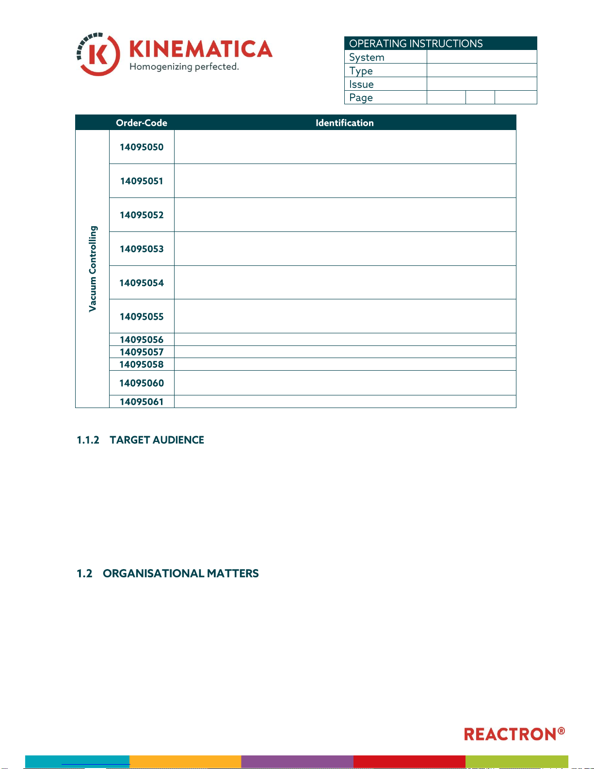
The data mentioned in this document refer to the machine(s)/ unit(s) with the following
identification:
Manufacturer: KINEMATICA AG, CH-6014 Luzern
Brand name: REACTRON®
Product name: REACTRON® System RT 1
Base
Syste
ms
14090010
REACTRON® RT 1 standard configuration, 230V (with EU-plug)
14090011
REACTRON® RT 1 standard configuration, 230V (with CH-plug)
14090012
REACTRON® RT 1 standard configuration, 115V
14095010
POLYMIX® PX-SR 90 D with digital display, instead of PX-SR 50 E
14095070
Funnel 1 ½“ Tri-Clamp
Dispersing
-
Systems
14095020
PT-MR 2100, 230 V with dispersing aggregate
PT-DA 2120/2G (mechanical seal version) and clamp for the lead-in hole on the cover,
suitable for the RT 1
14095021
PT-MR 2100, 115 V with dispersing aggregate
PT-DA 2120/2G (mechanical seal version) and clamp for the lead-in hole on the cover,
suitable for the RT 1
Temperature Controlling
14095040
Heating thermostat 230V, temp. Range 35°C-300°C, heating power 3.5 kW, max. 0.7 bar,
max. 25 l/min
14095041
Heating thermostat 115V, temp. Range 35°C-300°C, heating power 3.5 kW, max. 0.7 bar,
max. 25 l/min
14095042
Bath fluid, 10 liters, destilled water for temperatures between 5 - 90°C
14095043
Complete tubings made from VITON
14095044
Temperature measuring device with Pt 100 sensor and LC display box, 230V/EU
14095045
Temperature measuring device with Pt 100 sensor and LC display box, 230V/CH
14095046
Temperature measuring device with Pt 100 sensor and LC display box, 115V
Page 5
REACTRON®
RT 1
3.0 / 01.07.2018
5
of
36
Single step vacuum system for vacuum down to 100 mbar with single-step chemical
diaphragm pump with tubings and digital vacuum controller with key pad and LED-display,
230V / EU
Single step vacuum system for vacuum down to 100 mbar with single-step chemical
diaphragm pump with tubings and digital vacuum controller with key pad and LED-display,
230V / CH
Single step vacuum system for vacuum down to 100 mbar with single-step chemical
diaphragm pump with tubings and digital vacuum controller with key pad and LED-display,
115V
Double step vacuum system for vacuum down to 25 mbar with double-step chemical
diaphragm pump with tubings and digital vacuum controller with key pad and LED-display,
230V / EU
Double step vacuum system for vacuum down to 25 mbar with double-step chemical
diaphragm pump with tubings and digital vacuum controller with key pad and LED-display,
230V / CH
Double step vacuum system for vacuum down to 25 mbar with double-step chemical
diaphragm pump with tubings and digital vacuum controller with key pad and LED-display,
115V
LVS Laboratory vacuum system 2-step, 230V (EU)
LVS Laboratory vacuum system 2-step, 230V (CH), details see above
LVS Laboratory vacuum system 2-step, 115V, details see above
Vacuum hose connection for Clamp 1 1/2" fittings
suitable for RT 1 / RT 1 E – Systems, made of stainless steel 316 L, electropolished
Steam trap with vessel 500 ml at suction side
These operating instructions are intended for all authorised users of our
machines/equipment. We distinguish different user roles, taking account of the different demands
placed on the user by the activity to be carried out.
You will find the definitions of user roles with the demands on the user in chapter 2, “Safety”. You
can fulfil one or more of these roles, provided that you meet the corresponding demands.
If you are unable to find the answer to any question in the operating instructions, please contact
the equipment manufacturer directly.
Page 6
REACTRON®
RT 1
3.0 / 01.07.2018
6
of
36
The operating instructions can only be of use to you if you always have them to hand. They should,
therefore, always be kept at the place where the equipment is used.
Luzernerstrasse 147a Tel.: +41-41-259 65 65
CH-6014 Luzern Fax: +41-41-259 65 75
Switzerland e-mail: info@kinematica.ch
If you are unable to find the answer to any question in the operating instructions, please contact
the equipment manufacturer directly.
This should act as part of a quick-reference. The information is classified according to its application
and topic and is divided into the following parts:
This chapter describes the structure of this document
This chapter describes the safe use and optimum gain of the machine
This chapter describes the components of the machine
This chapter presents all information important for a safe installation and start-up of
the machine.
This chapter informs about service and maintenance.
This chapter points out how to order spare parts and what kind of spares you should
have in stock.
In this chapter you will find indications about break down, possible cause and repair.
In this chapter the warranty limit is defined
Page 7
REACTRON®
RT 1
3.0 / 01.07.2018
7
of
36
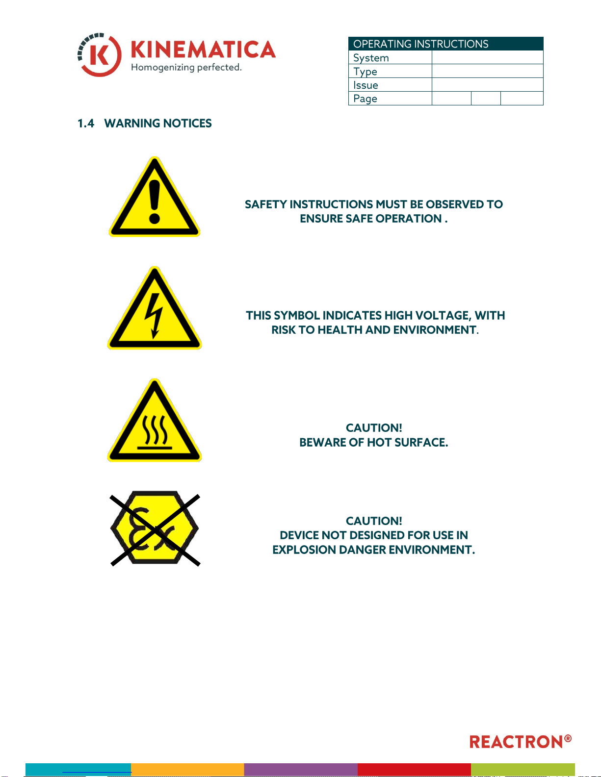
Please be aware of the meaning of the following warning signs:
Page 8
REACTRON®
RT 1
3.0 / 01.07.2018
8
of
36
This chapter is directed at all users of KINEMATICA laboratory equipment. It includes information
on safe and optimum use.
Any incorrect use of the installed equipment can be dangerous. Inadequately trained users can
cause material damage and personal injury. This chapter informs you of the safety concept and the
requirements for safe and optimum use of the equipment.
All those authorised to operate, service and repair the equipment are required to study chapter 2,
“Safety”.
The safety concept sets down the entitlement to use the equipment and the responsibilities of the
individual users.
The machines and equipment are designed and constructed according to the state of the art and
the recognised safety rules.
The equipment is designed and constructed for the following use:
▪ Dispersion and homogenisation of pumpable fluid products in accordance with the
technical specifications (see point 3.5) and compatibility with the materials coming into
contact with the products.
If you use the equipment for any purpose other than those listed, the manufacturer cannot be held
liable for any resulting damage.
Page 9
REACTRON®
RT 1
3.0 / 01.07.2018
9
of
36
Any use other than the “proper use” without the written approval of the manufacturer or operation
outside the technical limits of use is improper use.
To guarantee safety, we place requirements on the users of the equipment that must be met
without fail. Only persons meeting the requirements are authorised to work with the equipment.
We describe all those who work with the equipment as users. Since the requirements of these users
are very much dependent on their activity, we distinguish the following user roles.
The manufacturer can impose legal obligations on the contract partner when the equipment is
purchased. The contract partner is obliged to ensure that the equipment is properly used.
The operating company ensures that the equipment is properly used and authorises persons who
are entitled to work with the equipment in any one of the defined user roles. He is under the
obligation to instruct the users.
Contract partner and operating company can be the same person.
The service technician is an employee of the operating company and looks after the equipment in
special operating mode(s). He is a specialist with mechanical, electrical and electronic professional
training. The service technician undertakes commissioning, decommissioning service and repair of
the equipment. He must be appropriately trained to be able to carry out the service work required.
The operator turns the equipment on and off. In the event of an alarm signal he informs the service
technician.
Page 10
REACTRON®
RT 1
3.0 / 01.07.2018
10
of
36
The system danger area includes the whole system/equipment including the connecting lead and
controls.
This refers to all areas within a defined distance of the equipment.
This danger area includes all persons working with the equipment.
In order that the system/equipment can be used safely and without risk, the users in various roles
bear the responsibility for particular danger areas.
The contract partner bears the responsibility for the “proximity danger area”.
The operating company bears the responsibility for the “user danger area”. Only those users may
be authorised to operate the system/equipment who fulfil all requirements of the user roles
concerned. In so doing, attention must be paid to the following points:
◼ It is to be ensured that all users of the system/equipment have fully read and understood chapter
2, “Safety” and act accordingly in a safety-conscious manner.
◼ It is to be ensured that no unauthorised person carries out work with the system/equipment.
◼ It is to be ensured that users are informed of the possible risks and dangers connected with the
system/equipment.
◼ It is to be ensured that those being trained or engaged in general training are under the
permanent supervision of a trained and authorised person.
The service technician bears the responsibility for the “system/equipment danger area”. He ensures
that the system/equipment is at all times free from technical faults, safe and functions correctly.
Page 11
REACTRON®
RT 1
3.0 / 01.07.2018
11
of
36
Observe the following general safety rules:
◼ follow these operating instructions,
◼ in addition, observe the legal obligations and requirements for accident prevention and
environmental protection of the country in which you operate the equipment,
◼ do not make any modifications to the equipment without the written authorisation of the
manufacturer,
◼ only original replacement parts may be used for repairs,
◼ before any service work on the equipment, it must be ensured that the electrical supply is
switched off,
◼ after any service, maintenance or repair work has been carried out on the system/equipment, it
must be given a test run by the service technician.
◼ depending on the place at which it is installed, circumstances may require that hearing
protection is worn when remaining in the vicinity of the equipment for long periods.
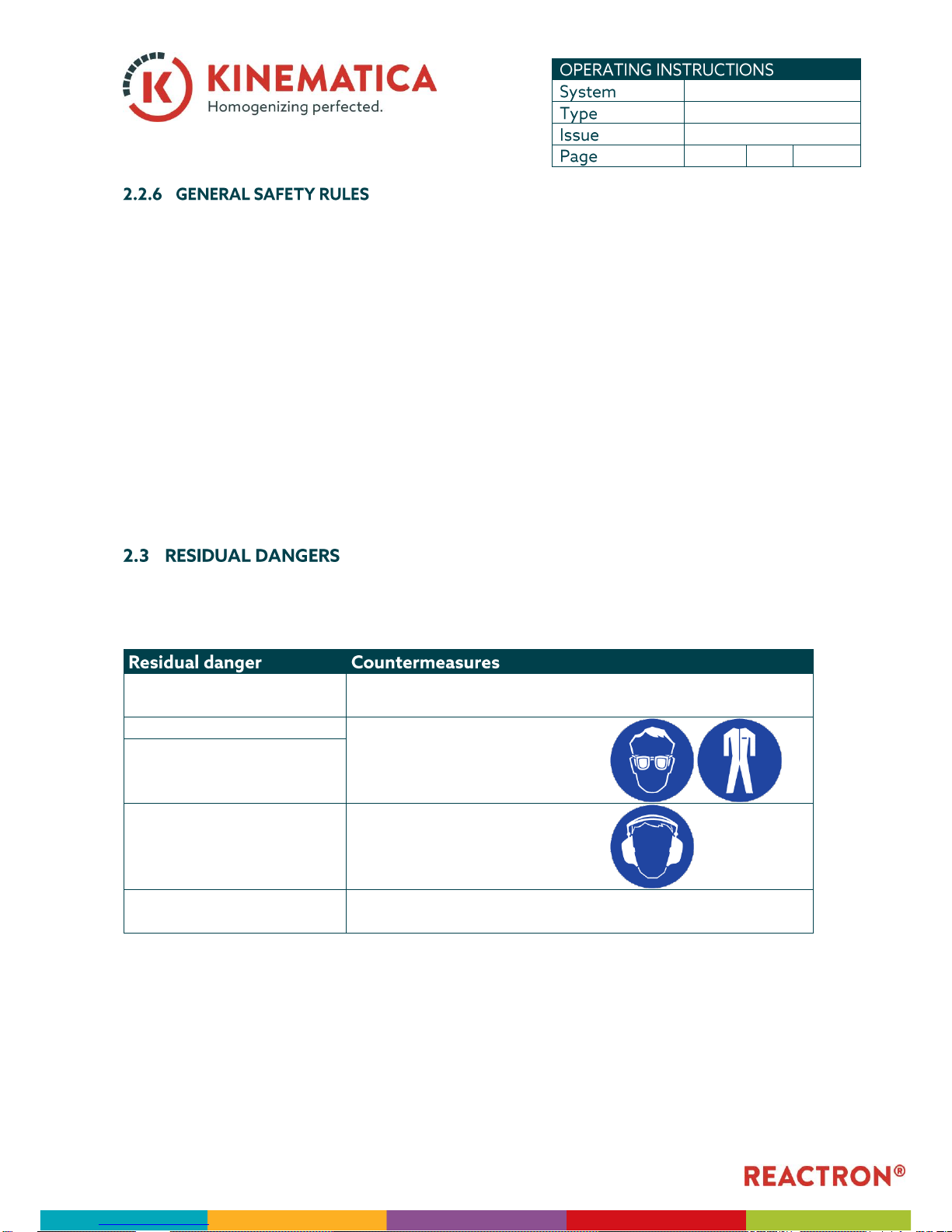
When the system/equipment is used in accordance with rules and regulations, residual dangers are
minimal.
Tripping over feed or return
lines
These should be laid appropriately.
Breakage of glass containers
Wear protective clothing (goggles
etc.).
Spitting of the product
Hearing loss due to loud
noise.
According to the application
ear protection must be used.
Tilting of the device
Use stable, non-slip base and the safety stands from
KINEMATICA
Page 12

REACTRON®
RT 1
3.0 / 01.07.2018
12
of
36
Page 13

REACTRON®
RT 1
3.0 / 01.07.2018
13
of
36
◼ The POLYTRON
®
PT 2100 (optional) is a batch mixing dispersion and homogenizing machine.
◼ The REACTRON
®
RT 1 needs a surface area of approx.. 440 x 400 mm and a height of approx.
1'200 mm
◼ The REACTRON
®
RT 1 has a weight of approx 37 kg
◼ The product to be processed must be flowable and pumpable.
◼ The dispersing generator has been selected for the contracted process, product and procedure
and shall therefore not be used for a different application without the permission of the
manufacturer.
◼ The steel parts in contact with the product are made of high-grade steel 1.4435 (ANSI 316 L)
◼ max. working pressure Process vessel : pressureless
Double jacket : max. 0.5 bar (g) (19 PSIA)
◼ working temperature max. 100°C (212°F)
◼ Speed max. PT 2100 : 30’000 RPM
Stirrer PX-SR 90 D : 400 RPM
Stirrer PX-SR 50 E : 300 RPM
Page 14

REACTRON®
RT 1
3.0 / 01.07.2018
14
of
36
The REACTRON RT 1 - System consists of:
◼ Process vessel with double jacket (3.2)
◼ POLYTRON
®
PT 2100 (3.3)
◼ Stirrer (3.4)
◼ Stand with pneumatic spring (3.5)
Description:
◼ Process vessel DN 120 with useable capacity of 1000 ml
◼ With Heating- / Cooling Jacket
◼ Mounted on a socket with vessel-holder and fixed with two hexagon socket set screws.
Page 15

REACTRON®
RT 1
3.0 / 01.07.2018
15
of
36
Process vessel
◼ Total Volume 1400 ml
◼ Working volume 1000 ml
◼ Operating pressure pressureless
◼ Working temperature max. 212 °F (100°C)
Dimensions
◼ Inside diameter 120 mm
◼ Outside diameter 155 mm
◼ Cyl. height 175 mm
Heating- / Cooling Jacket
◼ Heating/cooling volume approx. 1.1 liters
◼ Operating pressure max. 19 PSIA (0.5 bar)
◼ Working temperature max. 212 °F (100 °C)
Material
◼ Process vessel Borosilicate glass
◼ Heating- / Cooling Jacket Borosilicate glass
◼ Cover stainless steel 1.4435
◼ The cover is flanged to the vessel and tighten by a VITON-O-Ring
◼ The cover is equipped with two lifting lugs
Connections on the cover:
◼ Through-bore for anchor-stirrer (pre-mounted) with sealing
◼ 4 pc. NS29/32 conical connections
Connections in the Heating- / Cooling Jacket:
◼ Hose nipple DN 8 inlet of heating / cooling liquid
◼ Hose nipple DN 8 outlet of heating / cooling liquid
◼ none
Page 16

REACTRON®
RT 1
3.0 / 01.07.2018
16
of
36
See referring manual for drive
See referring manual for “PX-SR 50 E” or “PX-SR 90 D”
STAND:
◼ H-shape base
◼ Two columns
◼ The maximum height is approx 1100 mm.
◼ The base space required is 425 x 400mm.
Page 17

REACTRON®
RT 1
3.0 / 01.07.2018
17
of
36
The REACTRON® RT 1 system arrives completely assembled for 230V or 115V outlets. Plug the
power cable from the PT 2100 (optional) and plug the power cable from the stirrer in a suitable
outlet.
Page 18

REACTRON®
RT 1
3.0 / 01.07.2018
18
of
36
◼ Place the process-vessel into the vessel-holder using the two half-rings(red). Place the O-Ring
on the vessel-flange.
◼ Pull down the cover-unit using the knob. When the cover is touching the O-Ring-SEAL use the
fixing-knob to fix the cover-unit, then use the four fixing-screws of the vessel-holder to fix the
cover to the vessel.
fixing screws
2 half-ríngs
process-vessel
O-Ring
fixing-screws (4x)
fixing knob
knob
Page 19

REACTRON®
RT 1
3.0 / 01.07.2018
19
of
36
◼ The POLYTRON
®
can now be positioned in one of the four NS29/32-bores on the cover using
the NS29/32-Adapter. Same procedure for the funnel. Any other NS29/32-bore can be
equipped with any suitable NS29/32-device, such as Thermometer, vacuum-pumps, buckler
etc.)
NS29/32-adapter
with screws
POLYTRON
PT 10-35
funnel
Page 20

REACTRON®
RT 1
3.0 / 01.07.2018
20
of
36
◼ Pull the vacuum tube over the vacuum connection on the vessel and link it with the provided
vacuum system. For mounting the vacuum system, please see the referring manuals.
◼ The generator should be immersed in the product. This guarantees the proper cooling and
lubrication of the slide bearing.
◼ The force of suction of material into the generator is best between 1/3 and 2/3 of the vessel
height.
◼ Before connecting the electrical power supply, check the data sheet of the POLYTRON and the
stirring-unit
◼ To raise the cover-unit, first detach any vacuum-tubes on the cover, unfast the six fixing-screws
and then the fixing-knob at the cover-socket and the cover will raise automatically.
Page 21

REACTRON®
RT 1
3.0 / 01.07.2018
21
of
36
BEFORE STARTING THE UNIT MAKE SURE THE PROCESS VESSEL IS FILLED WITH THE PRODUCT TO BE
PROCESSED
◼ Check that the vessel cover and the POLYTRON
®
are mounted tight and correct
◼ Check that the anchor-stirrer does not interfere with the dispersing-unit.
Page 22

REACTRON®
RT 1
3.0 / 01.07.2018
22
of
36
◼ If the processed media tends to harden or stick, the product has to be removed completely from
process vessel after every use .The dispersing-unit, the anchor-stirrer and the cover have to be
cleaned.
◼ If the machine was not operated for a longer time, the POLYTRON
®
-aggregate has to be cleaned
(see Manual “PT 2100”)
◼ Before any maintenance work is carried out, the POLYTRON
®
-aggregate has to be cleaned
Page 23

REACTRON®
RT 1
3.0 / 01.07.2018
23
of
36
◼ The POLYTRON
®
has to be taken out of the process vessel
Page 24

REACTRON®
RT 1
3.0 / 01.07.2018
24
of
36
If one of the following irregularities is found during inspection, the machine / unit has to be
stopped immediately and repaired:
◼ Leakage of the whole system
◼ noise level too high or unusual noises from drives or dispersing aggregates
We strongly recommend that service work and repairs should be carried out only by authorised
KINEMATICA service centres or by KINEMATICA directly, where original replacement parts are available.
Any unauthorised modification or manipulation of the unit or its equipment leads to immediate
annulment of the warranty.
See corresponding manual
See corresponding manual
Page 25

REACTRON®
RT 1
3.0 / 01.07.2018
25
of
36
▪ For easy cleaning you can run the aggregate in any suitable cleaning fluid.
If further cleaning of the generator is needed, the dispersing aggregate and its components it has to be
disassembled as follows:
▪ Unfasten the rotor (5) by blocking the coupling. Assure that the spring does not hop away.
▪ Remove the mechanical seal (10)
▪ Remove the Stator (4) (left-hand thread) and the o-ring (8)
▪ Clean the removed components separately.
▪ Proceed in reverse order for reassembling.
▪ Ball Bearing
o To replace the ball bearing (3) do the de-assembling as shown above and remove
the retaining ring (7) at the shaft. Push out the shaft (1) and demount the ball
bearing (3). Replace the ball bearing and reassemble the aggregate.
▪ O-rings: as shown above
▪ Mechanical Seal: as shown above
Page 26

REACTRON®
RT 1
3.0 / 01.07.2018
26
of
36
Only original KINEMATICA spare parts will guarantee a trouble free operation of the machine
when ordering spare parts, please indicate:
Please refer to the bill of material in the APPENDIX to identify the required spare part.
When troubles with the POLYTRON and the dispersing-unit or the Stirrer occur, see corresponding
manuals.
The cover-unit does not raise
automatically.
The pneumatic-spring may be
damaged.
Change the pneumatic-spring
of the stand
Leakage of liquid between
cover and vessel.
O-Ring is damaged.
Replace the O-Ring
O-Ring, vessel and cover are not
centered well
Recenter these components (ORing has to be in the flute of
the bottom side of the cover)
Rattle noise
Foreign body in the vessel
touching anchor-stirrer and
dispersing-unit
Remove foreign body
Page 27

REACTRON®
RT 1
3.0 / 01.07.2018
27
of
36
KINEMATICA AG guarantees that the equipment that it produces will run free of any fault related to
materials or manufacturing faults for 12 months.
If thorough testing shows a fault to be due to either of the above causes, KINEMATICA AG
guarantees that the equipment will be repaired or replaced free of charge.
The guarantee does not cover parts that are subject to normal wear. It is void if any person other
than an employee of KINEMATICA AG or their appointed representative has made modifications to
the equipment or if the damage is due to failure to comply with the operating instructions, to
carelessness, accident, incorrect use or incorrect supply voltage.
KINEMATICA AG reserves the right to make technical changes to the equipment without modifying
equipment delivered earlier in the same way.
In the event of technical problems, for spare parts requirements or for advice, contact our regional
appointed agent, your preferred dealer or us directly at:
Luzernerstr. 147a Tel. +41-41-259 65 65
CH-6014 Lucerne Fax +41-41-259 65 75
Switzerland e-mail laboratory@kinematica.ch
Page 28

REACTRON®
RT 1
3.0 / 01.07.2018
28
of
36
REACTRON RT 1: drawing-no. 8.020-0008-2
Page 29

REACTRON®
RT 1
3.0 / 01.07.2018
29
of
36
bill of materials to drawing-no. 8.020-0008-3
Stirrer POLYMIX PX-SR 50 E
9158024
1
1
Extension tube RT 1
9753182
2
2
316 L
Gear i=5:1
9340962
3
1
Stand RT 1
9754097
4
1
Reactor RT 1 complete
9753207
5
1
Cardan joint DN8/10
9340971
6
1
Stainless steel
Zyl.-Schr. M8x110 A2
9918110
7
2
Stainless steel
Clamp sealing Tri-Clamp 1 1/2"
9324042
8 4 VITON
Clamp Tri-Clamp 1 1/2 "
9324043
9
4
316 L
Bellows Ø20&22
9340552
10
2
Rubber
Setcrew M4x5 DIN 916
9951059
11
2
Stainless steel
Momentunsupport RT
9753996
12
1
Stainless steel
Screw. M4x10 A2 I
9951107
13
4
Stainless steel
Page 30

REACTRON®
RT 1
3.0 / 01.07.2018
30
of
36
Stand RT 1: drawing-no. 6.030-0067-3
Page 31

REACTRON®
RT 1
3.0 / 01.07.2018
31
of
36
Bill of materials to drawing-no 6.020-0017-2 B
Socket
9753157
1 1 AlMgSi1
Boss head ST 2103
9750875
2 1 AlMgSi1
Cover socket
9754098
3 1 AlMgSi1
Cross beam
9753173
4 1 AlMgSi1
Pillar for stirrer
9754088
5
2
Stainless steel
Base right
9805052
6 1 AlMgSi1
Adjusting foot
9750856
7 1
Bolt
9751410
8 1 AlMgSi1
Pillar to stand
9751859
9
2
Stainless steel
Base left
9805053
10 1 AlMgSi1
Parallel pin Ø10h8x30
9991030
11 4 1.4305
U-shim M5
9960005
12 1 A2
Cylinder head screw M12x50
9911250
13 2 A4
Cylinder head screw M8x50
9900691
14 2 A2
Hexagon socket set screw M6x6
9951058
15 5 A2
Hexagon socket set screw M8x8
9900729
16 2 A2
Counter sunk screw M5x10R
9910510
17 4 A2
Knurled head screw M8x16 Ø50
9341076
18 1 Duroplast
Linear roll bearing
9340048
19
4
Stainless steel
Pneumatic spring
9340338
20 1
Decal WARNING
9340499
21 2
Decal REACTRON white
9340514
22 1
Rubber foot Ø21x6
9800070
23 4 Rubber
Knob EL 539-23-M10
9340328
24 1 Duroplast
Page 32

REACTRON®
RT 1
3.0 / 01.07.2018
32
of
36
Reactor complete RT 1: drawing-no. 6.020-0019-2 A
Page 33

REACTRON®
RT 1
3.0 / 01.07.2018
33
of
36
Bill of materials to drawing-no. 6.020-0019-2 A
Anchor stirrer
9753176
1 1 VITON
Cover RT 1
9753146
2 1 VITON
Vessel 1000ml DN120
9340528
3
1
Borosilicateglass
Distant piece
9753160
4 1 1.4305
Hollow shaft
9753159
5 1 316 L
Shim
9753162
6
2
Stainless steel
Sealing disc
9753163
7 1 POM black
Compensation spring
9340323
8
1
spring steel C75
Ball bearing Ø17/35x10
9322001
9
2
Stainless steel
Retaining ring A17
9990077
10
1
Stainless steel
Retaining ring I35
9990106
11
1
Stainless steel
Hexagon socket set screw M4x5
9951059
12 1 A2
O-ring DN 120 VITON
9342056
14 1 VITON
Vessel holder DN 120
9340308
15 1 PA
Shaft sealing ring
9340324
16 2 Gylon W
Decal "K" Ø50
9340515
17 1
O-ring Ø9.52x1.78
9341189
18 1 VITON
O-ring 20.24x2.62
9320066
19 1 VITON
Page 34

REACTRON®
RT 1
3.0 / 01.07.2018
34
of
36
Dispersing Aggregate PT-DA 2120/2 G: drawing-no. 1.020-0106-2 A
Page 35

REACTRON®
RT 1
3.0 / 01.07.2018
35
of
36
Bill of materials to drawing-no. 1.020-0106-2 A
Shaft complete 2120/2G
9752050
1 1 316 L
Shaft tube PT-DA 2120/2G
9752038
2 1 316 L
Ball bearing 688-ZZ
9322227
3 1 Stainless steel
Stator PTG 20/2 G
9752621
4 1 316 L
Rotor PTG 20/2
9752040
5 1 316 L
Counter ring retainer
9752041
6 1 316 L
Retaining ring A 8
9900808
7 1
O-ring 16x1
9320327
8 1 Viton
O-ring 4x1 Viton
9320326
9 1 Viton
Mecanical Seal
9735611
10 1 SBV
Spring retainer
9752604
11 1 316 L
Page 36

REACTRON®
RT 1
3.0 / 01.07.2018
36
of
36
 Loading...