

Page 1
MEGATRON® MT 5100 S²
General Operating Instructions
General Installation Instructions
General Maintenance Instructions
Page 2
INSTRUCTION MANUAL
System
MEGATRON®
Type
MT 5100 S
2
Issue
3.0 / 01.07.2018
Page
2
of
38
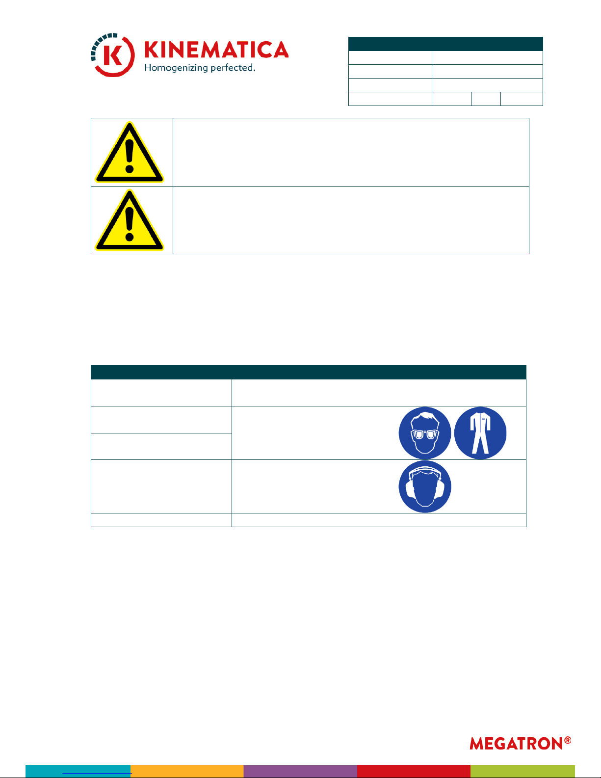
SAFETY INDICATIONS
Please pay attention to the meaning of the following warning signs:
SAFETY INSTRUCTIONS MUST BE OBSERVED TO ENSURE SAFE
OPERATION
THIS SYMBOL INDICATES HIGH VOLTAGE, WITH RISK TO
HEALTH AND ENVIRONMENT
CAUTION!
BEWARE OF HOT SURFACE
CAUTION!
BEWARE OF HAZARDOUS CHEMICALS OR MATERIALS THAT
ENDANGER HEALTH
CAUTION!
BEWARE OF ROTATING MECHANICAL PARTS
CAUTION!
DEVICE NOT DESIGNED FOR USE IN EXPLOSION DANGER
ENVIRONMENTS
Page 3
INSTRUCTION MANUAL
System
MEGATRON®
Type
MT 5100 S
2
Issue
3.0 / 01.07.2018
Page
3
of
38
GENERAL SAFETY INSTRUCTIONS
RESPECT THE INSTRUCTIONS GIVEN IN THIS DOCUMENT
READ THESE OPERATING INSTRUCTIONS BEFORE SWITCHING
ON OR OPERATING THE EQUIPMENT
IF YOU HAVE ANY QUESTIONS OR DOUBTS REGARDING
OPERATING THE UNIT, DO NOT START OR OPERATE THE UNIT
AND CONTACT YOUR DEALER OR NEAREST KINEMATICA
SERVICE CENTER
IMPROPER USE OF THE MACHINE / UNIT DUE TO
UNAUTHORIZED PERSONNEL CAN LEAD TO DAMAGE ON THE
MACHINE / UNIT AND / OR ENDANGER LIFE, CAUSE PERSONAL
INJURY AND HARM THE ENVIRONMENT
ALL AUTHORIZED PERSONNEL INVOLVED IN THE OPERATION,
THE SERVICE OR THE REPAIR OF THE MACHINE / UNIT HAVE TO
READ AND TO UNDERSTAND THIS MANUAL
ONLY AUTHORIZED PERSONNEL / INTENDED USERS ARE
ALLOWED TO USE THE MACHINE
THE INTENDED USER ASSURES THAT THE MACHINE / UNIT
WILL BE INSTALLED CORRECTLY IN ORDER TO FULFILL THE
INTENDED APPLICATION AND AUTHORIZES OTHER QUALIFIED
USERS TO WORK WITH THE MACHINE / UNIT. HE IS ALSO
RESPONSIBLE TO INSTRUCT THE USERS OF THE MACHINE /
UNIT
Page 4
INSTRUCTION MANUAL
System
MEGATRON®
Type
MT 5100 S
2
Issue
3.0 / 01.07.2018
Page
4
of
38
THE SERVICE ENGINEER IS EMPLOYED BY THE INTENDED USER
AND MAINTAINS THE MACHINE / UNIT DURING OPERATION.
HE IS A SKILLED CRAFTSMAN WITH MECHANICAL, ELECTRICAL
AND ELECTRONIC EDUCATION. THE SERVICE ENGINEER IS
RESPONSIBLE FOR THE INSTALLATION AND START-UP OF THE
MACHINE / UNIT AS WELL AS FOR THE MAINTENANCE AND
REPAIR OF THE MACHINE / UNIT. HE MUST BE TRAINED
ACCORDINGLY TO CARRY OUT ALL NECESSARY
MAINTENANCE WORK
ENSURE THAT ALL LEGAL AND ENVIRONMENTAL
REGULATIONS OF THE COUNTRY WHERE THE MACHINE / UNIT
WILL BE INSTALLED ARE FOLLOWED
DO NOT MODIFY THE MACHINE / UNIT WITHOUT A WRITTEN
CONFIRMATION BY KINEMATICA
IT IS STRICTLY FORBIDDEN TO RUN THE MACHINE / UNIT WITH
DISASSEMBLED OR BRIDGED SAFEGUARDS, FOR EXAMPLE
SAFETY LIMIT SWITCH, EMERGENCY SWITCH OR COVER
FOR REPAIRS, ONLY ORIGINAL SPARE PARTS SHOULD BE USED
BEFORE STARTING INSPECTION AND MAINTENANCE WORK
ON THE MACHINE / UNIT (SERVICE, REPAIR ETC.), ALL POWER
SUPPLIES MUST BE DISCONNECTED
THE DRIVE UNIT MAY ONLY BE OPENED BY AUTHORIZED
KINEMATICA SERVICE STATIONS
SERVICE AND MAINTENANCE SHALL ONLY BE PERFORMED BY
AUTHORIZED AND SKILLED SERVICE ENGINEERS
Page 5
INSTRUCTION MANUAL
System
MEGATRON®
Type
MT 5100 S
2
Issue
3.0 / 01.07.2018
Page
5
of
38
AFTER EVERY INSPECTION AND MAINTENANCE WORK ON THE
MACHINE / UNIT (SERVICE, REPAIR ETC.), THE SERVICE
ENGINEER HAS TO DO A TEST-RUN
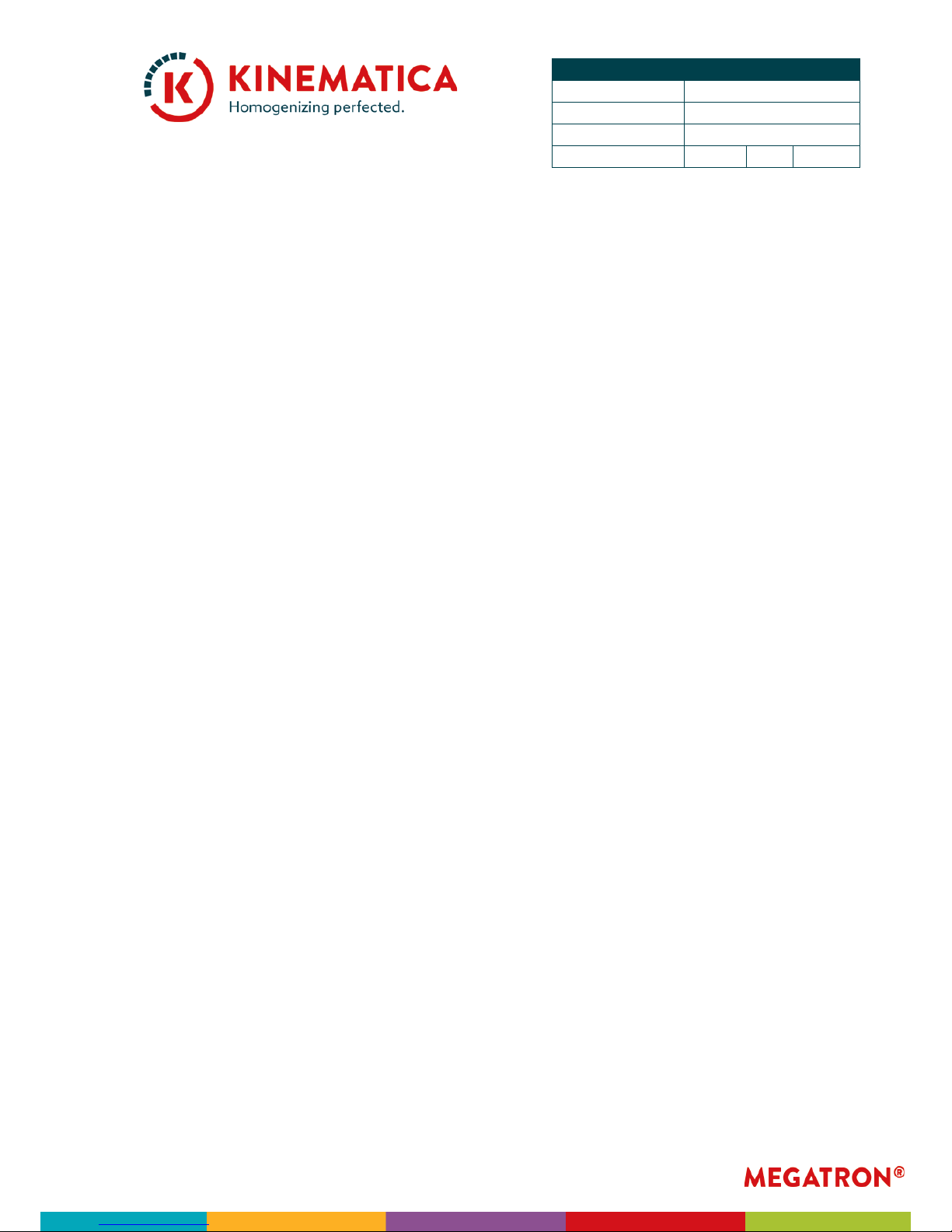
EAR PROTECTION SHOULD ALWAYS BE USED WHEN WORKING
IN THE ENVIRONMENT OF THE MACHINE
KEEP THIS OPERATING MANUAL NEARBY THE EQUIPMENT FOR
FUTURE REFERENCE
THIS DOCUMENT IS PART OF THE MACHINE / UNIT AND
SHOULD NOT BE REMOVED OR STORED ELSEWHERE
EASY ACCESS TO THE OPERATING AND MAINTENANCE CREW
MUST BE GRANTED AT ALL TIMES
ALTHOUGH MEGATRON UNITS ARE DESIGNED FOR EASY USE,
THIS DOES NOT RELEASE YOU FROM THE OBLIGATION TO
INSPECT YOUR EQUIPMENT CAREFULLY AND TO CLEAN IT
THOROUGHLY
Page 6

INSTRUCTION MANUAL
System
MEGATRON®
Type
MT 5100 S
2
Issue
3.0 / 01.07.2018
Page
6
of
38
WARNINGS
ALL WARNINGS AND RECOMMENDATIONS IN THE FOLLOWING
CHAPTERS MUST BE RESPECTED
THE EQUIPMENT MAY NOT BE OPERATED IN EXPLOSIVE AREAS
IT IS NOT ALLOWED TO WORK WITH FLUIDS WHICH ARE
HIGHLY INFLAMMABLE
IT IS NOT ALLOWED TO MIX MATERIALS WHICH CAN CAUSE
STRONG EXOTHERMAL REACTIONS
THE ELECTRICAL INSTALLATION MUST BE DONE BY A
QUALIFIED ELECTRICIAN!
ENSURE THAT THE RATED VOLTAGE OF THE EQUIPMENT
MATCHES THE SUPPLY
IT IS IMPORTANT THAT THE MAINS SUPPLY WHERE THE DEVICE
IS PLUGGED IN COMPLIES WITH THE INFORMATION ON THE
TYPE LABEL AND THE INTERNATIONAL STANDARDS FOR
POWER SUPPLIES. IF NOT, SUCCESSFUL OPERATION CANNOT
BE GUARANTEED
ENSURE THAT ENOUGH FREE SPACE IS AVAILABLE AT THE
BACKSIDE OF DEVICE, SO THAT EFFECTIVE AIR FLOW AND
COOLING IS ASSURED – INSUFFICIENT COOLING MAY LEAD TO A
DECREASE OF POWER OUTPUT
THE DEVICE HAS TO BE PLACED IN A MANNER THAT DIRT OR
FLUIDS CANNOT PENETRATE THROUGH THE VENTILATION
SLOTS AT BACK SIDE OF THE DRIVE
Page 7

INSTRUCTION MANUAL
System
MEGATRON®
Type
MT 5100 S
2
Issue
3.0 / 01.07.2018
Page
7
of
38
DIRECTION OF ROTATION IS COUNTER-CLOCKWISE SEEN FROM
FRONT ONTO THE COUPLING!
DRY-RUN OF MECHANICAL SEALS AND/OR SLIDE BEARINGS
MUST BE AVOIDED!
THE MECHANICAL SEAL MUST BE OPERATED WITH A SUITABLE
SEALANT LIQUID
THE QUENCH SYSTEM FOR THE MECHANICAL SEAL MUST BE
MONITORED BY THE INTENDED USER
THE INTENDED USER MUST ENSURE FLOW OF PRODUCT
THROUGH THE UNIT AT ALL TIMES
MEGATRON DISPERSION WORKING CHAMBERS MAY NOT BE
OPERATED DRY – THE MECHANICAL SEAL IS COOLED AND
LUBRICATED BY THE MEDIUM BEING PROCESSED AND THE
QUENCH MEDIUM. RUNNING DRY WILL DESTROY THE
MECHANICAL SEAL
Page 8
INSTRUCTION MANUAL
System
MEGATRON®
Type
MT 5100 S
2
Issue
3.0 / 01.07.2018
Page
8
of
38
THE MAX. OPERATIONAL SPEED IS INDICATED ON THE DATA
PLATE
THE INTENDED USER HAS TO ENSURE THAT NO FOREIGN
PARTICLES WHICH MIGHT LEAD TO A DAMAGE CAN PASS
THROUGH THE UNIT
THE ASSEMBLY AND DISASSEMBLY PROCEDURE IS DESCRIBED IN
THIS MANUAL
THE UNIT IS ONLY ALLOWED TO BE OPERATED WHEN
ASSEMBLED COMPLETELY
NEVER PULL THE COUPLING DURING OPERATION – THE
WORKING CHAMBER COULD FALL OUT OF THE COUPLING
THE WORKING CHAMBERS SHOULD BE CLEANED AFTER EVERY
OPERATION
THE INTENDED USER HAS TO ENSURE THAT USED SOLVENTS
AND CLEANING MATERIALS ARE COMPATIBLE WITH THE
MATERIAL OF THE SEALS AND COMPONENTS OF THE UNIT
THE RESPONSIBILITY OF KEEPING THE OPERATING
PARAMATERS SUCH AS PRESSURE, TEMPERATURE AND
PRODUCT FLOW WITHIN THE SPECIFIED LIMITS LIES WITH THE
INTENDED USER
SHAFT SEALS ARE NOT ALLOWED TO BE SUBJECT TO PRESSURE
Page 9
INSTRUCTION MANUAL
System
MEGATRON®
Type
MT 5100 S
2
Issue
3.0 / 01.07.2018
Page
9
of
38
IN THE EVENT THAT HAZARDOUS CHEMICALS OR MATERIALS
THAT ENDANGER HEALTH CAN INFLUENCE THE
SURROUNDINGS OR USE OF THE EQUIPMENT, APPROPRIATE
COUNTERMEASURES MUST BE TAKEN
WHEN HANDLING DANGEROUS PRODUCTS, TAKE CARE THAT
THE LOCAL SAFETY REGULATIONS ARE RESPECTED
AT LONG TERM USE, THE WORKING CHAMBER AND THE
BEARING HOUSING / COUPLING MAY GET HOT – DANGER OF
SKIN BURN
WHEN THE LINE CORD IS PLUGGED, NEVER TOUCH THE
COUPLING IN THE DRIVE – DANGER OF INJURIES DUE TO
ROTATING EDGES
IF THE MACHINE / UNIT IS USED FOR ANY OTHER PURPOSE
THAN THE INTENDED APPLICATION OR IF THE MACHINE / UNIT
WILL BE OPERATED BEYOND THE TECHNICAL DATA RANGE
WITHOUT THE WRITTEN APPROVAL BY KINEMATICA,
IMPROPER USE IS DECLARED AND KINEMATICA WILL TAKE NO
RESPONSIBILITY, NOR WILL GRANT ANY GUARANTEE
IMPROPER USE OF THE MACHINE / UNIT CAN RESULT IN
PERSONAL INJURY OR IN DAMAGE OF THE EQUIPMENT
KINEMATICA WILL NOT BE LIABLE AND WILL TAKE NO
RESPONSIBILITY IN SUCH AN EVENT
IF THE PROCESSED MEDIA TENDS TO HARDEN OR STICK IN
THE WORKING CHAMBER, THE PRODUCT HAS TO BE
REMOVED COMPLETELY FROM THE WORKING CHAMBER
PAY ATTENTION THAT THE TEMPERATURE DIFFERENCE
BETWEEN ACTUAL TEMPERATURE OF THE WORKING
CHAMBER AND CLEANING TEMPERATURE IS KEPT TO A
MINIMUM
Page 10
INSTRUCTION MANUAL
System
MEGATRON®
Type
MT 5100 S
2
Issue
3.0 / 01.07.2018
Page
10
of
38
A TEMPERATURE SHOCK CAN DAMAGE STRUCTURAL
COMPONENTS
THE CLEANING LIQUID SHOULD BE COMPATIBLE WITH THE
PARTS WETTED BY THE PRODUCT
BEFORE CLEANING WITH SOLVENTS, CHECK THE
COMPATIBILITY BETWEEN THE SOLVENT AND THE MATERIAL
OF THE O-RINGS
ALL MAINTENANCE WORK HAS TO BE DONE BY
SPECIALISTS OR ENGINEERS
BEFORE STARTING THE DISASSEMBLY, ALL ELECTRICAL
PARTS HAVE TO BE DISCONNECTED
BE SURE THAT THE MOTOR CANNOT BE STARTED FROM
ANOTHER PERSON, WHILE YOU ARE WORKING
CRANES AND/OR LIFTING EQUIPMENT MUST BE USED TO
MOVE AND TRANSPORT HEAVY MACHINERY
Page 11
INSTRUCTION MANUAL
System
MEGATRON®
Type
MT 5100 S
2
Issue
3.0 / 01.07.2018
Page
11
of
38
ALL PARTS HAVE TO BE INSPECTED FOR SIGNS OF WEAR AND
DAMAGE AND, IF NECESSARY, THEY HAVE TO BE REPLACED
BEFORE REASSEMBLY, ALL SCREWS HAVE TO BE GREASED
NEVER GREASE THE SEALING FACES OF THE MECHANICAL
SEALS
RESIDUAL DANGERS
When the system/equipment is used in accordance with rules and regulations, residual dangers are minimal.
Residual danger
Countermeasures
Tripping over feed or re-
turn lines
This should be laid appropriately
Breakage of glass contain-
ers
Wear protective clothing (gog-
gles etc.)
Splashing of the product
Hearing loss due to loud
noise
According to the application,
ear protection must be used
Tilting of the device
Use stable, non-slip base
Page 12
INSTRUCTION MANUAL
System
MEGATRON®
Type
MT 5100 S
2
Issue
3.0 / 01.07.2018
Page
12
of
38
List of Content
1 INTRODUCTION ................................................................................................ 13
2 DESCRIPTION OF THE EQUIPMENT ................................................................... 14
2.1 DRIVE UNIT ........................................................................................................................ 15
2.2 WORKING
CHAMBER ......................................................................................................... 16
2.2.1
DISPERSING GENERATORS ................................................................................................ 17
2.2.2 MECHANICAL SEAL ............................................................................................................ 18
2.2.3 FITTINGS FOR PRODUCT INLET & OUTLET ......................................................................... 19
3 INSTALLATION AND START-UP ........................................................................ 20
3.1 INSTALLATION .................................................................................................................. 21
3.1.1
MECHANICAL INSTALLATION ............................................................................................ 21
3.1.2 ELECTRICAL INSTALLATION .............................................................................................. 22
3.2 START-UP ......................................................................................................................... 22
3.3 SHUT-DOWN .................................................................................................................... 25
3.4 CLEANING ......................................................................................................................... 26
4 MAINTENANCE WORK ...................................................................................... 27
4.1 MAINTENANCE AND INSPECTION PLAN ............................................................................ 27
4.2 DISASSEMBLY
AND ASSEMBLY OF STANDARD WORKING CHAMBER ................................. 28
4.2.1
REPLACEMENT OF THE MECHANICAL SEAL ....................................................................... 29
4.2.2 REPLACEMENT OF THE BALL BEARINGS ............................................................................ 30
4.2.3 REPLACEMENT OF THE SHAFT SEALING RING .................................................................... 30
4.2.4 RESTART OF THE SYSTEM AFTER MAINTENANCE .............................................................. 30
5 SPARE PARTS ..................................................................................................... 31
5.1 ORDERING OF SPARE PARTS ............................................................................................. 31
5.2 RECOMMENDED
SPARE PARTS .......................................................................................... 31
6 FAULTS AND REMEDIES ..................................................................................... 32
7 TECHNICAL DATA ............................................................................................. 33
7.1 DRIVE UNITS ...................................................................................................................... 33
7.2 WORKING
CHAMBERS ....................................................................................................... 34
7.3 QUENCH
SYSTEMS ............................................................................................................ 35
7.5 DISPERSING
GENERATORS ................................................................................................ 36
7.6 FITTINGS
FOR PRODUCT INLET & OUTLET ......................................................................... 37
8 WARRANTY ....................................................................................................... 38
Page 13

INSTRUCTION MANUAL
System
MEGATRON®
Type
MT 5100 S
2
Issue
3.0 / 01.07.2018
Page
13
of
38
1 INTRODUCTION
KINEMATICA is a specialist for design and manufacturing of dispersing and mixing
machines. The aim of this document is to instruct new users in the effective and safe
utilization of our equipment.
The KINEMATICA Inline homogenizing system MEGATRON® MT 5100 S² has been
designed and manufactured according the CE guidelines, the actual technical
standards and applicable safety rules and is marked with the CE mark.
This document is valid for the KINEMATICA Inline homogenizing system
MEGATRON® MT 5100 S².
The system is designed and manufactured for the intended application consisting of:
• In-Line processing of flowable and pumpable products under the considera-
tions and limitations given in the “Technical Data”.
• The processed media must be compatible with all constructional parts wetted
by the product.
• If suitable precautions to personnel are taken to prevent any harm due to
noise emission.
• The use of the system with no structural, mechanical or electrical changes dif-
ferent from the original scope of supply.
Typical applications:
• Preparing emulsions
• Pharmaceutical or cosmetics products
• Suspending solids in liquids (such as liquid polymers)
• Dispersing fine solids in liquids or molten phases
• Suspending additives and solid polymers in mineral oils
• Extracting enzymes from biomass
• Extracting active ingredients and substances from plants, for example (when
used with REACTRON®)
• Grinding and shredding of solids and fibers in liquids or polymers
If the system is used for purposes different than or over and above the capabilities
specified herein, KINEMATICA does not guarantee proper function and assumes no
obligation or liability.
Should you have any questions which are not answered in this document, please
contact KINEMATICA.
Check on www.kinematica.ch for your closest contact address.
Page 14

INSTRUCTION MANUAL
System
MEGATRON®
Type
MT 5100 S
2
Issue
3.0 / 01.07.2018
Page
14
of
38
2 DESCRIPTION OF THE EQUIPMENT
For a ready-to-use system you need:
• Drive unit MEGATRON® MT 5100 S²
• A working chamber MTO/MTK 5100 Q
• A recirculation system (can also be supplied by the customer)
Drive Unit
Working
Chamber
Example of a customized and
extended recirculation system
Page 15

INSTRUCTION MANUAL
System
MEGATRON®
Type
MT 5100 S
2
Issue
3.0 / 01.07.2018
Page
15
of
38
2.1 DRIVE UNIT
The drive unit contains the powerful three-phase high frequency motor (with quick
coupling for the working chamber) controlled by the integrated VFD installed in a
stainless steel housing.
Main Switch
On/Off
Control panel
with Display
Quick coupling
for the working
chamber
Stop button
Start button
Speed Down
Speed Up
Enter Programming
Mode VFD
Speed
Display
Page 16

INSTRUCTION MANUAL
System
MEGATRON®
Type
MT 5100 S
2
Issue
3.0 / 01.07.2018
Page
16
of
38
2.2 WORKING CHAMBER
The working chamber is a flow through in line chamber.
The working chamber consists of the following general parts:
• Bearing
• Mechanical sealing
• Inner chamber with dispersing generator and product inlet/outlet connections
• Cooling/Heating jacket if applicable
Product
Inlet
Product
Outlet
Cooling/Heating Jacket
(optional)
Dispersing
Generator
Coupling /
Bearing
Mechanical
Seal
Page 17

INSTRUCTION MANUAL
System
MEGATRON®
Type
MT 5100 S
2
Issue
3.0 / 01.07.2018
Page
17
of
38
2.2.1 DISPERSING GENERATORS
A dispersing generator consists of a rotor and a stator. Rotor and stator consists of
one or more teeth rows each for different levels of fineness.
Turning with high speed, the rotor creates inside the stator high mechanical shear
forces and shear stress resulting in size reduction and turbulent mixing of the processed media.
The generators are exchangeable with different types for different particle sizes.
Please bear in mind due to operation the dispersing generator(s) belong to the wear
and tear parts.
Rotor
Stator
Teeth / Teeth
row(s)
Page 18

INSTRUCTION MANUAL
System
MEGATRON®
Type
MT 5100 S
2
Issue
3.0 / 01.07.2018
Page
18
of
38
2.2.2 MECHANICAL SEAL
The product side of the working chamber (inner chamber with dispersing generator)
has to be separated from the non-product or atmospheric side of the working chamber. For that purpose, a single mechanical seal is installed inside the working chamber.
The type and material combination of the mechanical seal have been chosen for the
application described in the contract and should therefore not be used for other purposes without the permission of the manufacturer.
A mechanical seal is not allowed to run dry. Moreover, it has always to be lubricated,
flushed and cooled by a suitable sealing lubricant. The lubricant must also be compatible with the product and the materials of construction. The lubricant temperature has always to be 40°C below the boiling point to prevent any damages to the
sealing system.
In the case of a single mechanical seal, a pressureless quench liquid system (flow
through or pressureless tank) is used.
The standard working chambers for the MEGATRON® MT 5100 S² can be equipped
with a KINEMATICA quench system TS1 (also available with vessel made of PTFE)
Vessel Cover
Quench vessel
Standpipe
Quench outlet
Quench inlet
Page 19

INSTRUCTION MANUAL
System
MEGATRON®
Type
MT 5100 S
2
Issue
3.0 / 01.07.2018
Page
19
of
38
IF YOU DO NOT USE A QUENCH SYSTEM TS1, YOU HAVE TO
CONNECT A FLOW-THROUGH, UNPRESSURIZED COOLING
LIQUID PIPING (E.G. TAP WATER) AND A FLOW RATE ≤ 1 L/MIN
2.2.3 FITTINGS FOR PRODUCT INLET & OUTLET
The standard inlet and outlet connections at the working chamber are inside thread
G1/2”.
Different standard fittings are available and can be screwed into the connections:
• Tri-Clamp ¾”
• Milk thread DN15
• Hose nipples DN15
G1/2”
G1/2”
Page 20

INSTRUCTION MANUAL
System
MEGATRON®
Type
MT 5100 S
2
Issue
3.0 / 01.07.2018
Page
20
of
38
3 INSTALLATION AND START-UP
The drive unit MEGATRON® MT 5100 S² will be delivered completely assembled and
the package will include:
• Drive unit
• Mains cable
• Manual
The working chamber will be delivered completely assembled and the package will
include:
• Working Chamber (as ordered, optional)
• Dispersing Generator (as ordered, optional)
• Quench System (as ordered, optional)
• Product inlet & outlet fittings (as ordered, optional)
• Cooling/heating jacket (as ordered, optional)
Other accessories or equipment will be packed separately and delivered as ordered.
Always check the delivery note and check immediately when unpacking the unit. Always report immediately any irregularities.
Page 21

INSTRUCTION MANUAL
System
MEGATRON®
Type
MT 5100 S
2
Issue
3.0 / 01.07.2018
Page
21
of
38
3.1 INSTALLATION
3.1.1 MECHANICAL INSTALLATION
• The MEGATRON
®
has to be positioned on an even surface or foundation. Ensure that no vibrations can be transmitted onto the MEGATRON®. Please
check if there is a sufficient air circulation.
• The working chamber has to be connected to the drive unit by using the quick
coupling. Simply push back the slide ring of the quick coupling, fit the working
chamber into the coupling and release the slide ring again.
Page 22

INSTRUCTION MANUAL
System
MEGATRON®
Type
MT 5100 S
2
Issue
3.0 / 01.07.2018
Page
22
of
38
• Check that the quick coupling has secured the working chamber against turn-
ing and/or removing.
• To remove the working chamber from the drive unit, simply push back the
slide ring of the quick coupling and carefully remove the working chamber
from the coupling.
• Connect product inlet and outlet lines and necessary supply lines (e.g. cooling
water, sealing liquid…). A seal should always be used to avoid leakages. The
piping should not generate any forces (stresses, vibrations) on the working
chamber nozzles.
3.1.2 ELECTRICAL INSTALLATION
• Before connecting the electrical power supply using the mains cable, check
the “Technical Data” as well as the data on the drive tag plate.
3.2 START-UP
• Check if all connections, piping and supply lines are tight and mounted cor-
rectly.
• Remove the cover of the quench vessel and fill up the quench system with
the sealing liquid.
• The sealing liquid has to be compatible with the product, the seals and the
mechanical seal. The sealing liquid is not within the scope of supply of
KINEMATICA.
• Use enough sealing liquid so that the standpipe is always covered. Otherwise
the mechanical seal will be damaged.
• Check that the filling level remains constant.
Covered
height
Page 23

INSTRUCTION MANUAL
System
MEGATRON®
Type
MT 5100 S
2
Issue
3.0 / 01.07.2018
Page
23
of
38
• Open the inlet and outlet product circuits.
• Check all connections, piping and supply lines for signs of leakage.
• The piping containing the product to be processed must be free of air pockets
and air enclosures.
• For starting the MEGATRON
®
, push the On/Off button.
• In ON position, the main switch will light up and the speed display will show
“Stop”. The system is ready to start.
Page 24

INSTRUCTION MANUAL
System
MEGATRON®
Type
MT 5100 S
2
Issue
3.0 / 01.07.2018
Page
24
of
38
• Then push the green RUN “I” button in order to start the unit. The unit will in-
crease the speed to the last set speed.
• Use the Up/Down buttons to increase or decrease the speed.
• The unit will increase/decrease the speed to the new set speed.
INFO: It is also possible to set first the desired speed level with the Up/Down buttons and then starting the unit with the green RUN “I” button.
Speed indication
Page 25

INSTRUCTION MANUAL
System
MEGATRON®
Type
MT 5100 S
2
Issue
3.0 / 01.07.2018
Page
25
of
38
3.3 SHUT-DOWN
• Use the Down buttons to decrease the speed to “0”.
• Push the red STOP “O” button to stop the unit.
INFO: It is also possible to push the red STOP “O” button to stop the unit without
decreasing the speed first. When pushing the green RUN “I” button again, the unit
will increase again to the last set speed.
Page 26

INSTRUCTION MANUAL
System
MEGATRON®
Type
MT 5100 S
2
Issue
3.0 / 01.07.2018
Page
26
of
38
• Push the On/Off button. In OFF position, the light of the main switch and
speed display will vanish and the system will shut down.
• Finally, close the inlet and outlet circuits if applicable
3.4 CLEANING
• If the processed media tends to harden or stick, the product has to be re-
moved completely from the working chamber after every use.
• If the machine is not operated for a longer time or before any maintenance
work is carried out, the working chamber has to be cleaned.
• There are different methods to clean the working chamber, depending on the
customer’s facilities:
o The product can be pushed out under pressure; do not use higher pres-
sure than the normal working pressure to avoid damage to the mechanical seal and preventing product from entering the bearing area;
o Or the working chamber can be disassembled.
Page 27

INSTRUCTION MANUAL
System
MEGATRON®
Type
MT 5100 S
2
Issue
3.0 / 01.07.2018
Page
27
of
38
4 MAINTENANCE WORK
• The MEGATRON
®
MT 5100 S² drive unit is designed to be almost maintenance-free. Nevertheless to guarantee a long lifetime the unit should always
be used with care.
• The attached working chamber contains several wear parts which have to be
checked and/or exchanged regularly depending on the use of the unit, mainly:
o Ball bearings
o Mechanical Seal, Shaft Seal
o O-Rings
o Dispersing Generator
• Keeping these wear parts as spare parts on site is mandatory to avoid longer
interruptions during maintenance and service – see also chapter “spare parts”.
• Before any maintenance work the working chamber of the MEGATRON
®
has
to be rinsed out, emptied completely and cleaned.
4.1 MAINTENANCE AND INSPECTION PLAN
The MEGATRON® has to be inspected regularly in order to assure an optimum and
safe operation.
DAILY INSPECTION WORK
If one of the following irregularities is found during inspection, the machine has to be
stopped immediately and repaired:
• Leakage of the sealant fluid out of the opening in the mechanical seal housing
• Leakage of the whole piping system
• Overheated bearing housing
• Noise level too high or unusual noises
• Foreign body in the working chamber
YEARLY INSPECTION WORK OR EVERY 3000 RUNNING HOURS
• Signs of wear of the generator, deformation of the generator,
• Phenomena of wear and damages on the mechanical seal
• Replacing the ball bearings
Page 28

INSTRUCTION MANUAL
System
MEGATRON®
Type
MT 5100 S
2
Issue
3.0 / 01.07.2018
Page
28
of
38
4.2 DISASSEMBLY AND ASSEMBLY OF STANDARD WORKING CHAMBER
This procedure is valid for the working chamber MTO 5100 Q (23005017).
Before demounting, please drain the working chamber completely and remove the
quench connections.
• Remove the inlet and outlet connections.
• Unfasten the screws (24) and remove cover (4).
• Remove stator (9) carefully out of the working chamber.
• Fix the shaft (7) using a bolt (max. Ø5mm) and unfasten the rotor (10) using the
disassembly tool. The rotating ring of the mechanical seal (26) will come off
with the rotor.
• Unfasten the screws (25) and remove the chamber (6). The static ring of the
mechanical seal (26) will come off with the chamber.
• Unfasten the screws (23) and remove the seal housing (2). Take care of the
shaft seal (31) and the spring of the mechanical seal (26).
• Fix the shaft (7) and unfasten the crown coupling (8).
Page 29

INSTRUCTION MANUAL
System
MEGATRON®
Type
MT 5100 S
2
Issue
3.0 / 01.07.2018
Page
29
of
38
• Push the shaft (7) with ball bearings (19, 18) out of the bearing housing (1) into
direction of the generator.
• If necessary, remove the locking ring (21) and the compensation disc (22) from
the bearing housing (1).
• Remove the locking ring (20) and pull off the ball bearings (18, 19) from the
shaft.
• Mount the new ball bearings on the shaft and dispose the used ones (do not re-
install pulled off ball bearings).
4.2.1 REPLACEMENT OF THE MECHANICAL SEAL
When mounting the mechanical seal (26), assure that the spring is in the correct position. Assure that the slide areas of the mechanical seal are clean and do not contain
any hard solid particles – solid particles in the slide areas may cause break down of
the mechanical seal.
Mechanical seals always have to be replaced as a complete set. Replacing just the
static or the rotating face of the mechanical seal leads to strong and fast wear of the
sliding faces.
Static Ring of the
mechanical seal
Rotating Ring of the
mechanical seal
Page 30

INSTRUCTION MANUAL
System
MEGATRON®
Type
MT 5100 S
2
Issue
3.0 / 01.07.2018
Page
30
of
38
PROTECT THE MECHANICAL SEAL AGAINST STROKES AND
POKES, IT CAN BE DAMAGED EASILY
NEVER GREASE THE SLIDE SURFACES AND ROTATING RINGS.
WHEN REPLACING THE MECHANICAL SEAL, DO NOT REPLACE
SINGLE PARTS. WE RECOMMEND TO TAKE A WHOLE NEW
SPARE MECHANICAL SEAL AND SEND THE DAMAGED ONE
BACK TO THE NEAREST KINEMATICA REPRESENTATIVE
4.2.2 REPLACEMENT OF THE BALL BEARINGS
To put on new ball bearings (18,19) on the shaft, they must be heat up to 120 °C (not
more than 130°C). Heated ball bearings can then be mounted on the shaft without
strong effort.
4.2.3 REPLACEMENT OF THE SHAFT SEALING RING
Grease the shaft sealing ring (31) before mounting it. Assure that the grease is in
compliance with your application and product. When using EPDM sealings, never
use grease based on mineral oil.
4.2.4 RESTART OF THE SYSTEM AFTER MAINTENANCE
The assembly of the working chamber has to be done in reverse order. Before starting up with real product, please assure the correct function of the system using water.
Page 31

INSTRUCTION MANUAL
System
MEGATRON®
Type
MT 5100 S
2
Issue
3.0 / 01.07.2018
Page
31
of
38
5 SPARE PARTS
Only original KINEMATICA spare parts will guarantee a trouble free operation of the
machine.
See also the “Technical Data Sheet” and the referenced documentation, drawings
and parts lists.
5.1 ORDERING OF SPARE PARTS
when ordering spare parts, please indicate:
1. Type of machine (e.g. MEGATRON® MT 5100 S²)
2. Serial-No. indicated on the machine data plate (e.g. 823-0017-01-02)
3. Position, description and ident number according to the Parts List (e.g. Pos. 1,
Shaft, 9750001)
5.2 RECOMMENDED SPARE PARTS
To avoid any inconvenience or time delays when handling service or repair cases, it is
strongly recommended to hold on stock some main and/or critical components like:
• Mechanical seal
• Ball bearings
• O-Rings
• Shaft
• Dispersing Generator(s)
Please bear in mind that some components have lead times of several weeks.
Do not hesitate to contact KINEMATICA for a corresponding quotation or advise.
Page 32

INSTRUCTION MANUAL
System
MEGATRON®
Type
MT 5100 S
2
Issue
3.0 / 01.07.2018
Page
32
of
38
6 FAULTS AND REMEDIES
Fault
Possible causes
Remedy
Noise in the bearing
housing
Dusty, dirty or damaged
bearings
Replace the bearings
Rattle noise
Foreign body in working
chamber
Remove foreign body
Vibrations
Twisted shaft Replace the shaft
Faulty bearings Replace the bearings
Foreign body in working
chamber
Remove foreign body
Rotational speed exceeded Reduce the speed
Bearing housing hot
Faulty bearing housing Replace bearing housing
Damaged bearings Replace bearings
Wrong grease Use specified grease
Rotational speed exceeded Reduce the speed
Leakage of sealing liquid Mechanical seal damaged Replace mechanical seal
No throughput of product
Air in working chamber
Remove air out of product line
Viscosity of product too
high
Install a feed pump in
front of the
MEGATRON
®
Display shows “CL”
Current Limit reached, Motor overload
Verify drive/motor are
proper size for application
Display shows “FCL”
Fast Current Limit, Overload
Verify drive/motor are
proper size for application
Page 33

INSTRUCTION MANUAL
System
MEGATRON®
Type
MT 5100 S
2
Issue
3.0 / 01.07.2018
Page
33
of
38
7 TECHNICAL DATA
7.1 DRIVE UNITS
Description
Drive Unit MEGATRON® MT 5100 S²
Order Code
23005060
23005061
23005062
23005063
Plug type
CH
EU
UK
US
motor type
AC motor 3-phase, gearfree direct drive
supply voltage
1-phase, 230 V ~
supply frequency
50/60 Hz
max. speed 21’000 rpm
input power
Max. 2’000 W
output power
Max. 1’500 W
soft-start
Yes
noise emission (drive
only)
Lower than 62 dB(A)
direction of rotation
Counter clockwise, seen from front
ambient temperature
0 – 40°C
relative humidity
80% max. non-condensing
standards
Manufactured according to EN / IEC regulations for
EMC & SAFETY
protection type
IP 20
max. period of continuous
operation
100 %
Coupling type
F
weight (drive only)
Approx. 21.2 kg
324 mm
322 mm
255 mm
Page 34

INSTRUCTION MANUAL
System
MEGATRON®
Type
MT 5100 S
2
Issue
3.0 / 01.07.2018
Page
34
of
38
7.2 WORKING CHAMBERS
Description
MTO 5100 Q
MTK 5100 Q
Order Code
23005017
23005010
Stages
1 (for one dispersing generator)
Cooling / Heating
jacket
No Yes, connections 2xG1/8”
Max. speed
21’000 rpm
Working
Temperature
max. 90°C
Working pressure
max. 6 bar(g)
Differential pres-
sure
max. 2 bar(g) between product inlet-outlet
Working pressure
jacket
N/A Max. 4 bar (g)
Mechanical Seal
Type 2031-012 QBV-G
Q=Silicon-Carbide / B=Carbon / V=Viton /G=Stainless Steel
Quench connec-
tions
Yes, G1/8”
Quench pressure
Pressureless (continuous or with quench vessel)
Materials wetted
by the product
Stainless steel 316 L
O-Rings/Gaskets made from Viton
Surface finish
Electropolished
Surface roughness
Product wetted parts Ra ≤ 1.6 µm
Product requirements
The product must be pumpable and must not contain solid particles
that may destroy the mechanical seal
Product
Viscosity
Depending on the temperature, pressure and products properties,
the dynamic viscosity should not exceed:
Approx. 500 mPas
CIP
No
SIP
No
Autoclavable
No
Weight
Approx. 3.0 kg
Other versions incl. autoclavable design available on request.
Page 35

INSTRUCTION MANUAL
System
MEGATRON®
Type
MT 5100 S
2
Issue
3.0 / 01.07.2018
Page
35
of
38
7.3 QUENCH SYSTEMS
Description
TS1 (Standard)
TS1 PTFE
Order Code
23005020
23005021
Volume
Approx. 350 ml
Materials
Acryl, PU, SS, Viton
PTFE, Teflon, SS, EPDM
Autoclavable
No
Yes
Page 36

INSTRUCTION MANUAL
System
MEGATRON®
Type
MT 5100 S
2
Issue
3.0 / 01.07.2018
Page
36
of
38
7.5 DISPERSING GENERATORS
Dispersing generators MTG ../. X
Order code
23005011
23005012 23005013
2300501
4
23005015
23005016
2300501
8
2300502
5
Type
MTG
30/2 M
MTG
30/4 F
MTG
40/2 G
MTG
40/4 M
MTG
40/6 F
MTG
40/6 FV
MTG
40/6 FF
MTG
40/6 FFV
Rotor Ø
29 mm
31 mm
37 mm
39 mm
41 mm
41 mm
41 mm
41 mm
Stator Ø
37 mm
37 mm
46 mm
46 mm
46 mm
46 mm
46 mm
46 mm
Max. speed
21’000
rpm
21’000
rpm
18’000
rpm
18’000
rpm
17’000
rpm
16’000
rpm
16’000
rpm
16’000 rpm
Max. flow
[l/min]
50 40 60 50 45 45 45 45
Materials
Stainless steel 316 L
Surface fin-
ish
Electropolished
Surface
roughness
Ra 1.6 µm
Cleaning
Sterilizable and autoclavable at all common methods
Page 37

INSTRUCTION MANUAL
System
MEGATRON®
Type
MT 5100 S
2
Issue
3.0 / 01.07.2018
Page
37
of
38
7.6 FITTINGS FOR PRODUCT INLET & OUTLET
Description
Order no.
Hose nipple DN15
(set of 2)
23005022
Milk thread DN 15
according to DIN
11851
(set of 2)
23005023
Tri-Clamp ¾”
(set of 2)
23005024
Page 38

INSTRUCTION MANUAL
System
MEGATRON®
Type
MT 5100 S
2
Issue
3.0 / 01.07.2018
Page
38
of
38
8 WARRANTY
This KINEMATICA unit is warranted to be free from defects in material and workmanship without wear and tear parts for a period of 24 months.
KINEMATICA will repair or replace and return free of charge any part which is returned to its factory within said period, transportation prepaid by the user and which
is found upon inspection to have been defective in materials or workmanship. The
warranty includes both, parts and service, without charge.
This warranty does not include normal wear from use; it does not apply to any instrument or part which has been altered by anyone other than an employee, which
has been damaged through accident, negligence, failure to follow operating instructions, the use of electric currents or circuits other than those specified in this manual, misuse or abuse.
KINEMATICA reserves the right to change, alter, modify or improve any of its instruments without obligation to make corresponding changes to any instrument previously sold or shipped.
The foregoing obligations are in lieu of all other obligations and liabilities including
negligence and all warranties, of merchantability or otherwise, expressed or implied
in fact or by law and state our entire and exclusive liability and buyer's exclusive remedy for any claim of damages in connection with the sale or furnishing of goods or
parts.
KINEMATICA will in no event be liable for any special or consequential damages
whatsoever and their liability under no circumstances will exceed the contract price
for the goods for which liability is claimed.
Made in Switzerland by
KINEMATICA AG
Luzernerstrasse 147a
CH-6014 Littau / Lucerne
Tel.: +41-41-259 65 65
Fax: +41-41-259 65 75
e-Mail: info@kinematica.ch
 Loading...