

Page 1

User’s Guide
Revisions and Modifications
October 2005
Introduction and Overview
The remote monitoring system uses wireless technologies for monitoring temperatures on parts of power
system equipment. The system consists of battery-powered remote sensor/transmitters (RST), a ground-based
receiver for collecting the data from the sensors (Ground station Collector - GSC) and a data collection
computer which collects the data from one or more GSC and makes it available for viewing and other purposes.
Experience gained with the first pilot installations led to the development of a second prototype – with
incremental improvements over the original system. The second prototype was intended to expand the scope of
the trial installation and, at the same time, address some of the issues identified with the initial installation.
Specifically, the changes and improvements are as follows:
• Redesigned RST layout to facilitate assembly and improve reliability (from assembly-related issues)
• New RST is now configurable to emit RF signals constantly, for the purposes of evaluating signal
strength for optimal placement of components
• Improved antenna performance based on as-assembled conditions
• Additional hardware in the GSC to permit signal strength measurements
• Modified firmware in the GSC to permit recording of signal strength. Firmware is compatible with old
st
generation) GSC, except that “zeros” will be recorded in place of signal strength
(1
• Simplifed version of the GSC in a handheld configuration for evaluating the received RF signal strength
from individual RSTs
• Improved communications software for the data collection computer, and improvements to the
corresponding portions of the GSC firmware to permit more reliable download of data.
Page 2
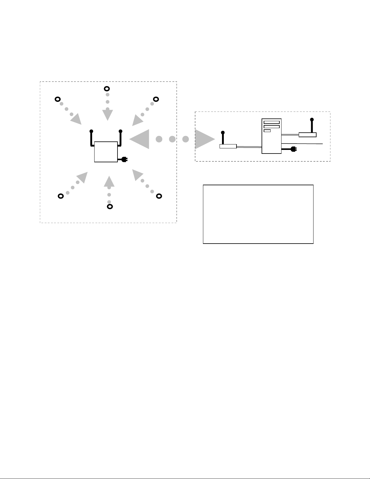
The overall function of the various components are identical to the original system and are illustrated in the
W
following figure.
RST
GSC
RST
RST
RST
Switchyard
RST
RST
Station building
Computer
SL
RST Remote Sensor/Transmitter
installed on Switchgear
GSC Ground Station Collector
WSL Wireless Serial Link Master
“FreeWave”
Figure 1 – System overview
Cell Modem or
standard phone
line
Remote Monitoring System – 2nd Generation Instructions Page 2 of 13
Page 3

PART A - Remote Sensors/Transmitters (RST)
nd
The 2
The internal firmware is identical in the two versions. The normal operation of the two versions is also
identical. However, the 2
following describes the differences and other specific notes that pertain to the new version.
1. The RSTs are delivered DISABLED by Kinectrics
2. When installing the RST, keep in mind that the antenna is just below the surface of the “black box”.
3. When installing the RST, apply a small quantity of thermal compound to the bottom of the RST plate
4. The RSTs each have a series of pins (“header”) exposed along one side of the box (see figure 2).
5. To ENABLE the RST in normal mode
6. To ENABLE the RST in TEST mode
Generation RSTs are packaged differently than the original version but otherwise operate identically.
nd
Generation version has some enhancements not present in the first version. The
The antenna radiation pattern is provide separately and should be considered during installation and the
placement of the receivers (GST)
to ensure good contact between the equipment and sensor. Do not use excessive quantities – a small
“dab” to give a thin layer is sufficient. The bolt used to secure the RST should be securely tightened
but care should be taken not to deform the RST plate. Wipe clean any excess thermal compound
• Carefully insert on activation strip into the pins of the header and make sure it is seated firmly –
make sure to make note of the correct orientation (figure 2). The activation strip is NOT
mechanically keyed but is colour-coded. The grey side should face up. (note that some of the pin
positions on the activation strip are not used).
• once the activation strip is installed, the RST is active and in NORMAL mode – temperatures on
the base plate are measured and broadcast every 15 minutes.
• once activated, the activation strip may be sealed with silicone rubber (provided) to prevent ingress
of moisture
• The RST uses an internal high temp, long-life battery which should last 5-10 years
• Carefully insert the test adapter into header by carefully lining up the pins (figure 3). Note that the
test adapter should be properly centered and aligned (note that some of the pin positions on the
test adapter are not used).
• The red LED on the test adapter should illuminate
• The RST will continuously broadcast RF at the carrier frequency (50% duty cycle); no data is
transmitted
• the handheld receiver (HSM) can be now used to evaluate signal strength
• while in test mode, the external battery on the test adapter is used – the internal battery is not
depleted. The internal battery is a AA-size 3.6V lithium. The battery should have a very long life
but can be replaced with special tools, if required.
Remote Monitoring System – 2nd Generation Instructions Page 3 of 13
Page 4
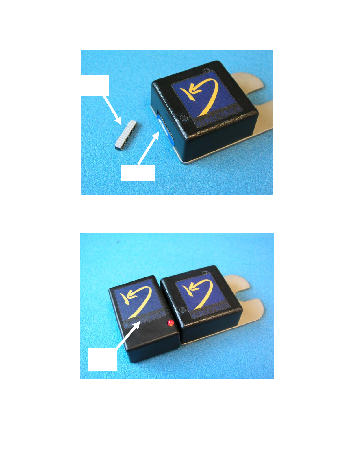
Activation Strip
(grey side up)
“header”
Figure 2 – 2nd Generation remote temperature sensor (RST). The location of the ‘header’ is shown on the
left. The activation strip (grey side up) should be carefully inserted and seated fully into the header for
NORMAL mode operation. The opening can be filled with silicone rubber, if desired.
Test
adapter
Figure 3 – Test Adapter connected to the RST. Care should be taken in aligning the pins appropriately.
The test adapter will be centred and the red LED will illuminate when installed properly.
Remote Monitoring System – 2nd Generation Instructions Page 4 of 13
Page 5

PART B –Ground station collector
nd
The 2
components to permit the measurement of received signal strength and new firmware. Consequently, the new
circuit board is slightly larger than the previous version. The new firmware allows for the recording of the
received signal strength (for diagnostic purposes) and facilitates improved communications with the data
collection computer.
The 2
antenna on the left is used to communicate to the remote sensor transmitters. (The one on the right is used for
Freewave communications).
PART B2 – Handheld Receiver/signal strength meter (HSM)
The handheld receiver consists of a battery-powered GSC that only utilizes the electronics specific to the
measurement of signal strength. Consequently, the internal circuit board is largely empty. The output of the
electronics is tied to two front panel meters which are calibrated to display the relative strength of the received
RST signal (in test mode) on a (approximate) scale between 0-100. The two meters (one is an analog “meter”
and the other a numeric display) are wired in parallel and are functionally equivalent (figure 7).
Generation GSC is identical to the 1st generation version, except for the addition of some hardware
nd
Generation GSC is equipped with 2 “whip” antennae, similar to those of the 1st Generation design. The
Figure 7 – Handheld Signal
Meter (HSM)
Remote Monitoring System – 2nd Generation Instructions Page 5 of 13
Page 6

The HSM can be turned on by using one of two switches on the side of the unit. The lower switch (black) is a
“momentary” switch which keeps the unit on only while the button is depressed. The upper switch (red) is a
standard on/off switch. We recommend that the momentary switch be normally used in order to conserve
battery life.
Signal strength can be evaluated as follows:
>50 - preferred (approximately)
>20 - will function normally but with little or no margin to accommodate signal reduction due to
adverse conditions
Under some conditions, the received level may fluctuate, depending on local conditions and noise.
Unfortunately, this behaviour is often observed with RF signals and should not be construed as a “malfunction”
of the device.
The HSM is delivered with a standard antenna with SMA connector, similar to that used on the GSC. By
changing the antenna type, performance with different antenna systems can be evaluated. Remember that
antenna orientation could also impact on the received signal strength.
The HSM will only work properly for a single RST in test mode. However, other RST in nomal mode will not
greatly impact on the HSM function – these transmissions are only sometimes seen as a momentary “blip” in
the meter’s response.
The HSM is powered by a standard 9V (alkaline) battery, which can be replaced as required.
Remote Monitoring System – 2nd Generation Instructions Page 6 of 13
Page 7

Part C – Software upgrade for Data Collection Computer
The data collection computer operates identically as in the previous version but, a software upgrade is required.
The new software (version 3.15) has improved communication via the freewave to the ground station collectors
but, these are largely transparent to the user. A new “maintainance mode” feature has been added to facilitate
diagnostics and a few extra settings have been added to the “settings” page.
General instructions for installing and using the software, whether as a standard application or as a service, are
the same as for the previous version and are not repeated here. However please note that the user interface is
normally not available when running as a service – please remember to adjust the settings accordingly by
running the software first as an application so that the software starts up in the proper mode for automated
operations when run as a service.
The following describes the various functions of the user interface, when run as an application;
Other than some minor cosmetic changes, the main interface is similar to that of the previous version. As
before, the system can be in standby mode or automated mode (data collection occurs automatically), which can
be activated manually by the START and STOP buttons on the main page.
Figure 8 – main RMON Screen
Receiver List
Remote Monitoring System – 2nd Generation Instructions Page 7 of 13
Page 8

The basic call list is accessed through the “receiver List” icon or menu item (when the system is in standby
mode – i.e. no automated data collection)
Figure 9 – changing the call list
multiple receiver Freewave Access “numbers” may be input here. When the main software starts an data
collection cycle, each of the receivers in this list is sequentially polled and data downloaded from each. If the list
is empty, RMON will attempt to connect to the “wired receiver” directly connect to the COM port (i.e. no
freewave).
RMON Settings
The system settings can be accessed through the Settings icon or menu item on the main page, when the
software is in standby mode. These settings can also be accessed by directly editing the INI file. New settings
featured in the 2
nd
generation software are indicated.
“Show this value in the log when a device is not present” – the listed number (‘999’ in the figure) will be
placed in the downloaded data log when the auxiliary devices (external temp sensor, pressure sensor,
nd
etc) are not connected. All 2
Generation NYPA sensors do not use external devices.
“Show this value when a sensor error occurs” – self explanatory
nd
**NEW** “Signal Strength Scaling factor” – 2
Generation GSCs will record the received signal strength
for each transmission (for diagnostic purposes). The scaling factor can be applied, optionally, to the
internally generated number (the A/D output) to facilitate interpretation. We recommend that a
value of 0.3 be used – this will result in a signal strength number ranging from about 0-100 (can be
interpreted as a “percent signal strength”) and will be approximately correlated with the equivalent
reading on the HSM with the RST in test mode.
st
Generation GSCs with the updated firmware, are not capable of recording received signal strength.
1
For these a “0” will be recorded.
Communications Port – COM port used for the freewave connection
Logfile directory – folder where the log file (downloaded data) will be stored
Remote Monitoring System – 2nd Generation Instructions Page 8 of 13
Page 9

Startup Mode – choices are ‘immediate’, ‘delayed’ or ‘standby’.
- Immediate - Automatic download is intiated - data download occurs first, followed by a wait
period.
- Delayed – Automatic download is initiated - Wait period occurs first, followed by the data
download.
- Standby – automatic download is not initiated. Automatic download is initiated manually by
pressing the ‘Start’ button.
Startup Position – choices are ‘normal’ or ‘minimized’ – initial Window state on startup
Receiver call frequency – the duration of the “wait” period between successive data downloads when in
automatic download mode. Duriation is provided in seconds.
Retry Frequency – In the event an error occurs during the download of data, the software will wait the
specified number of seconds before trying again.
**NEW** No. of Retries – In the event an error occurs during the download of data, this number defines the
number of times the software will “retry” to download data. If all the data is not downloaded following
the number of retries, the software will repeat the download process at the next download cycle (after
the wait period).
Figure 10 – RMON Settings Page
Maintenance Mode (**NEW**)
Remote Monitoring System – 2nd Generation Instructions Page 9 of 13
Page 10

The Maintenance mode is accessed through the icon or menu item when the software is in Standby mode.
Figure 11 – RMON Maintenance mode screen
In maintenance mode, the user can directly connect to one specific GSC, as controlled by the combo box and
buttons at the top of the screen. The accessible receivers are taken from the main list specified earlier. A
directly wired receiver is also available on the list.
Memory Pointers - The section “Memory Pointers” allows the user to manipulate the memory pointers of the
GSC.
• The first two parameters represent the MSB and LSB of the data pointers (point in memory
containing the most recently acquired data).
rd
• The 3
and 4th positions represent the MSB, LSB of the download pointers (point in memory
containing the data most recently transferred from the GSC by the RMON software.
• The last parameter is a flag (0 or 1) that indicates if the acquired (not transferred) data has exceed
memory capacity (data will “wrap around” and the oldest data will be overwritten)
Remote Monitoring System – 2nd Generation Instructions Page 10 of 13
Page 11

• The various buttons allow the user to read the current pointer values, write back pointer values and
reset the pointers back to the start of memory.
Download Records - The section “Download Records” allows the user multiple data download options.
• The option “catch up” will download all data not yet downloaded (the data between the download
and the data pointers)
• The option “Download all records” will download the entire memory contents, starting from the
location of the download pointer
• All download options will update the download pointer, except for the option “Download Single
Record”. However, the memory pointer display will not be updated unless the pointers are “read”
again.
• Downloaded data can be directed to the log file, to the screen for immediate viewing and can be
viewed as raw data in HEX or as processed by the RMON software (as is normally done)
Date/Time - The last section “Date/time” allows the user to poll the GSC’s internal date/time setting or
synchronize the GSC’s clock with the computer system clock running the RMON software
DATA FILE FORMAT
The data format is identical to the 1st generation systems, except for the addition of a signal strength parameter
at the end. This parameter is an approximate value used for diagnosing transmission problems for the system.
Example output file (as viewed by MS Excel)
27/09/2005 9:48 1 911-0335 39 23 3.67 999 999 68.4
27/09/2005 9:48 1 911-0335 33 22 3.62 999 999 66.3
27/09/2005 9:49 1 911-0335 38 23 3.65 999 999 69.9
27/09/2005 9:49 1 911-0335 37 22.5 3.64 999 999 62.1
27/09/2005 9:49 1 911-0335 29 25 3.65 999 999 70.5
The fields from left to right are as follows:
1. Date/time – date and time corresponding to this line of data
2. System ID – usually “1” for this prototype
3. GSC ID – Access number - resembles a telephone number
4. Sensor ID – a serial number such as 1, 2, 3,….etc.
5. Internal Temp – temp in deg C of the on-board temperature
6. Battery voltage – used for diagnostic purposes, nominally 3V
7. Auxiliary input – not used (shown as 999)
8. external temp - not used (shown as 999)
9. signal strength
Note: - the ‘signal strength’ parameter is now measured onboard and is provided to assist in diagnosing
reception problems. The numbers presented should be used as a rough estimate and should not be
taken as an absolute or precise measure of signal strength. Large variations in the numerical value could
be observed for properly operating sensors.
Remote Monitoring System – 2nd Generation Instructions Page 11 of 13
Page 12

Contact Information
Noboru (“Nobby”) Fujimoto
416-207-6250
noboru.fujimoto@kinectrics.com
Silvano Rizzetto
416-207-6359
silvano.rizzetto@kinectrics.com
Remote Monitoring System – 2nd Generation Instructions Page 12 of 13
Page 13

RESIDENTIAL EQUIPMENT
CLASS B DIGITAL DEVICE
INFORMATION TO USER
This device complies with Part 15 of the FCC Rules. Operation is subject to the
following two conditions: (1) This device may not cause harmful interference, and
(2) This device must accept any interference received, including interference that
may cause undesired operation.
This equipment has been tested and found to comply with the limits for Class B
Digital Device, pursuant to Part 15 of the FCC Rules. These limits are designed to
provide reasonable protection against harmful interference in a residential
installation. This equipment generates, uses, and can radiate radio frequency
energy and, if not installed and used in accordance with the instructions, may
cause harmful interference to radio communications. However, there is no
guarantee that interference will not occur in a particular installation. If this
equipment does cause harmful interference to radio or television reception, which
can be determined by turning the equipment off and on, the user is encouraged to
try to correct the interference by one or more of the following measures.
• Reorient or relocate the receiving antenna
• Increase the separation between the equipment and receiver
• Connect the equipment into an outlet on a circuit different from that to which the
receiver is connected
• Consult the dealer or an experienced radio/TV technician for help
Any changes or modifications not expressly approved by the party responsible for
compliance could void the user’s authority to operate the equipment.
Please note that the following product label must be placed near or made
part of the model label:
This device complies with Part 15 of the FCC Rules. Operation is subject to the
following two conditions: (1) This device may not cause harmful interference, and
(2) This device must accept any interference received, including interference that
may cause undesired operation.
Remote Monitoring System – 2nd Generation Instructions Page 13 of 13
 Loading...