

Kinder Rocco MK2, KCFL**RN2 Series Installation And Maintenance Instructions Manual

Rocco MK2
Model No. KCFL**RN2
DECORATIVE LOG EFFECT ROOM HEATER
Installation and Maintenance Instructions
Hand these instructions to the user
Model No. KCFL**RN2 is for use on Natural Gas (G20) at a supply pressure
of 20 mbar in G.B. / I.E.
** Denotes trim & colour variant

CONTENTS
P
AGE
Section 1 Information and Requirements
1
.0 Appliance information 3
1.1 Conditions of installation 4
1
.2 Flue & Chimney Suitability 4
1
.3 Shelf position 5
1.4 Hearths 5
1.5 Installation to plastered wall surfaces 5
Section 2 Installation of Fire
2.1 Unpacking the combustion chamber 6
2.2 Preparing the combustion chamber opening (In studded wall) 7
2.3 Preparing the combustion chamber opening (In chimney breast) 8-9
2.4 Fitting the mounting frame 10
2.5 Installation of the gas supply 11
2.6 Removal & re-fitting of the glass frame 12
2.8 Connection of the flue liner and fitting of the draught diverter 13-14
2.9 Fitting of the flue terminal and fitting of the draught diverter 15
Section 3 Assembling Fuel Bed and Commissioning
3.1 Fitting the fuel bed logset 16-20
3.2 Making the gas connection & checking for gas tightness 20
3.3 Lighting the appliance 21-23
3.4 Removal & re-fitting the trim 23
3.5 Checking for clearance of combustion products 24
Section 4 Maintenance
4.1 Removal of the burner assembly 25
4.2 Removal of the control valve 25-26
4.3 Removal of the ultrasonic reciever 26
4.4 Removal of the pilot assembly 26
4.5 Removal / Replacement of batteries in the Ultrasonic Receiver 27
4.6 Removal / Replacement of the handset battery 27
Model number KCFL**RN2 manufactured by:-
BFM Europe Ltd. Trentham Lakes, Stoke-on-Trent, Staffordshire, ST4 4TJ
Appliance Efficiency Declaration
The efficiency of this appliance has been measured as specified in
BS EN 7977-1 : 2002 and the result is 52%.
The gross calorific value of the fuel has been used for this efficiency calculation.
The test data from which it has been calculated has been certified by Advantica.
The efficiency value may be used in the UK Government’s Standard Assessment
Procedure (SAP) for energy rating of dwellings.
2
SECTION 1
INFORMATION AND REQUIREMENTS
1.0 APPLIANCE INFORMATION
Main injector : (1 off) Bray Injector Cat 82 – size 420 (NG)
Pilot Type : Copreci ODS 21100 / 141
Max. Gross Heat Input : 6.9 kW
Min. Gross Heat Input : 3.5 kW
Gas Rate : 0.634 m3/hr (High)
0.325 m3/hr (Low)
Cold Pressure : G20 20.0+/-1.0 mbar (8.0 +/- 0.4 in w.g.)
Ignition : Integral to gas valve
Electrode Spark Gap : 4.0mm
Packed Weight Combustion Chamber : 33.0 kg
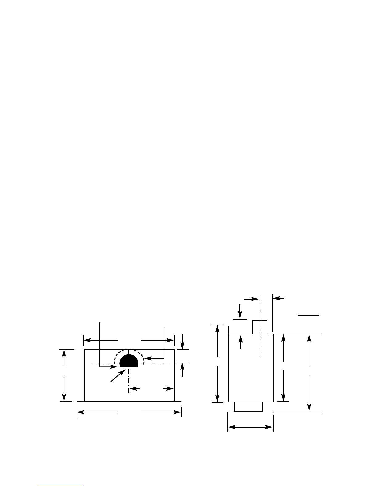
Fig. 1
Top View of Combustion Side View of Combustion
Chamber Chamber
3
795 mm
750 mm
353 mm
375mm
Flue
Spigot
138mm
550mm
480mm
138mm CRS
353mm
436mm
135mm
Flat Edge of Flue Termination
must be installed facing front
of product only.
Minimum 50mm
clearance required
around flue outlet
as shown by dotted
line

INSTALLATION REQUIREMENTS
1.1 CONDITIONS OF INSTALLATION
It is the law that all gas appliances are installed only by a CORGI Registered
Installer, in accordance with these installation instructions and the Gas Safety
(Installation and Use) Regulations 1998 as amended. Failure to install appliances
correctly could lead to prosecution. It is in your own interest and that of safety to
comply with the law. The installation must also be in accordance with all relevant
parts of the Local and National Building Regulations where appropriate, the
Building Regulations (Scotland Consolidation) issued by the Scottish Development
Department, and all applicable requirements of the following British Standard Code
of Practice.
1. BS 5871 Part 3 Installation of Decorative Fuel Effect Gas Fires
2. BS 6891 Installation of Gas Pipework
3. BS 5440 Parts 1 & 2 Installation of Flues and Ventilation
4. BS 1251 Open fire place components
5. BS 715 / BS EN 1856-2 Metal flue pipes for gas appliances
6. BS EN 1858 Clay Flue Blocks and Terminals
7. IS 813 : Domestic Gas Installation (Republic of Ireland)
No purpose made additional ventilation is normally required for this
appliance, when installed in G.B. When Installing in I.E. please consult
document I.S. 813 : Domestic Gas Installation, which is issued by the
National Standards Authority of Ireland. If installing in Northern Ireland,
please consult local building regulations. Any purpose made ventilation
must be checked periodically to ensure that it is free from obstruction.
1.2 FLUE AND CHIMNEY SUITABILITY
This appliance is designed for use with conventional brick built or lined chimneys
and fabricated flues and metal flue boxes conforming to BS 715 / BS EN 1856-2.
All flues must conform to the following minimum dimensions.
Minimum diameter of circular flues 125 mm
Minimum effective height of all flue types 4 metres
ENSURE THAT IF INSTALLING THIS PRODUCT INTO A BRICK BUILT CHIMNEY, THE CHIMNEY HAS
BEEN FULLY SWEPT PRIOR TO PROCEEDING WITH THE INSTALLATION. IT IS RECOMMENDED
IN PROPERTIES WITH LARGE C HIMNEY CROSS-SECTIONAL AREA’S THAT A 125MM
DIAMETER FLUE LINER IS FITTED. IF THE CHIMNEY HEIGHT EXCEEDS 10 METRES ON AN
EXTERNAL WALL OR 12 METRES ON AN INTERNAL WALL, THE CHIMNEY MUST BE FULLY
LINED. AS WITH ALL HOLE IN THE WALL TYPE ROOM HEATERS, PLEASE ENSURE THAT YOU
ARE MEASURING THE EFFECTIVE FLUE HEIGHT FROM THE TOP OF THE COMBUSTION
CHAMBER, NOT THE BASE OF THE CHIMNEY
Safe clearance of products must always be checked by carrying out a smoke match test as described on
page 24.
4
1.3 SHELF POSITION
The fire may be fitted below a combustible shelf providing there is a minimum
distance of 300mm above the top of the fire and the shelf does not project more
than 150mm. If the shelf overhangs more than 150mm the distance between the
fire and the shelf must be increased by 15mm for every 25mm of additional
overhang over 150mm.
1.4 HEARTHS
This appliance does not require the fitting of a hearth that projects in front of it
when installed into a recess in either an existing chimney breast or a studded wall.
The appliance must however stand on a non-combustible base that is a minimum
thickness of 12mm
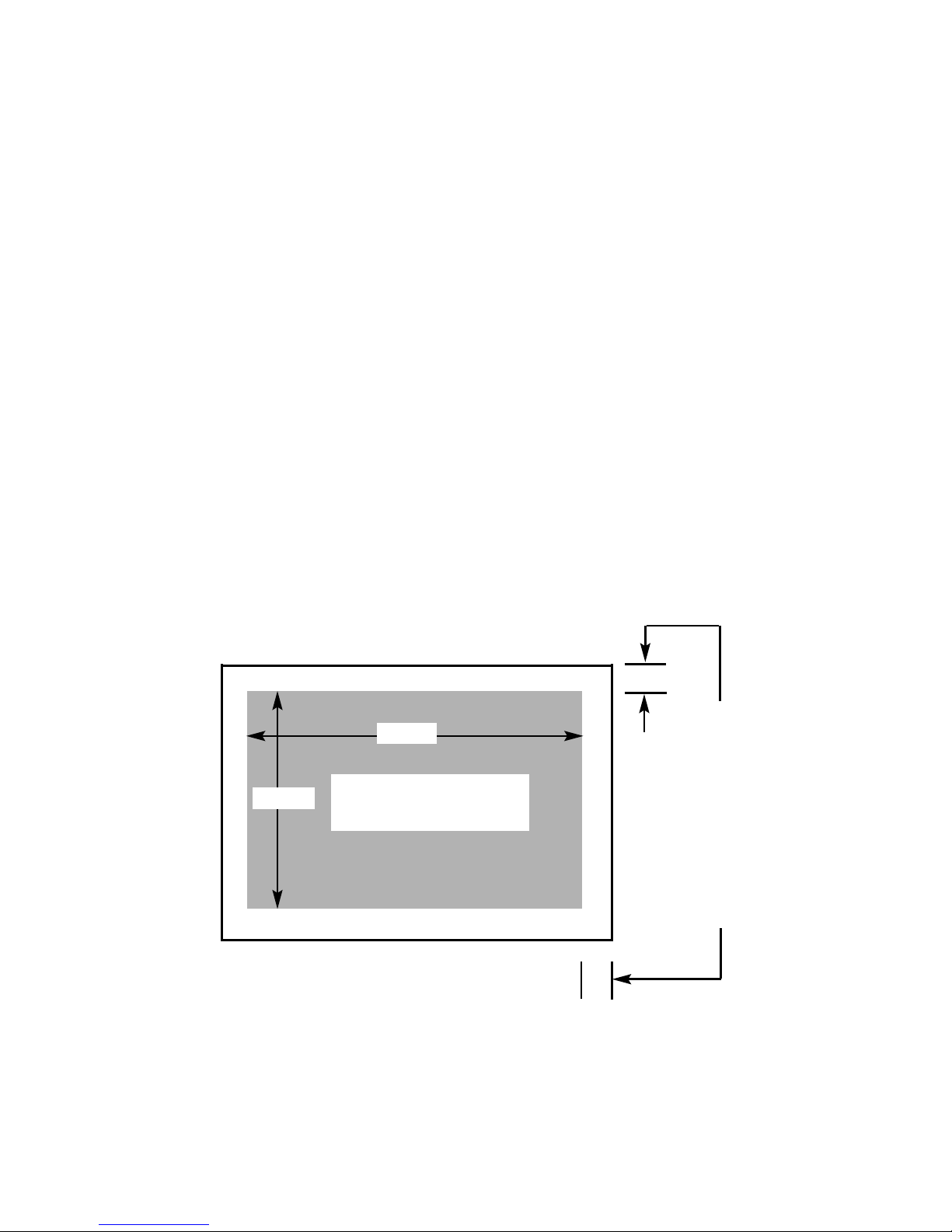
1.5 INSTALLATION TO PLASTERED WALL SURFACES
If installing to a plastered wall, all material must be removed from the 50mm area
surrounding the combustion chamber opening, and replaced with non-combustible
material, such as marble or granite, to prevent plaster cracking. See Fig. 2 below
The mounting frame supplied must always be used.
Fig. 2
5
Combustion Chamber
Opening in Studded Wall or
Existing Chimney Breast
750mm
540mm
Minimum 50mm of
material to be removed
all round perimeter of
combustion chamber
and replaced with
marble, granite or other
non-combustible
material to create a
sealing area. Secure
combustion chamber via
four off mounting holes
in mounting frame

SECTION 2
INSTALLATION OF FIRE
2.1 UNPACKING THE COMBUSTION CHAMBER
Carefully lift the combustion chamber out of the carton. Remove the loose item
packaging carefully from the pack. Check the contents as listed :-
DO NOT UNDER ANY CIRCUMSTANCES USE THIS APPLIANCE IF THE
GLASS PANEL IS BROKEN OR NOT SECURELY FIXED TO THE FIREBOX.
Packing Check List
1 off Combustion Chamber & Glass Frame Assembly
1 off Trim (packed in front section of combustion chamber pack)
1 off Boxed ceramic fuel-bed set (packed inside combustion chamber)
1 off 125mm flue spigot adaptor (packed inside combustion chamber)
1 off Flue terminal assembly (packed inside combustion chamber)
1 off Draught diverter assembly (packed inside combustion chamber)
1 off Installation Instruction Manual
1 off User Instruction Manual
1 off Length of foil tape
1 off Handset & 1 off 9V Battery
1 off 20mm mounting frame & 4 off 10mm x 4mm mounting frame screws
1 off Loose Items pack – containing :-
4 off No. 12 x 40mm Screws
4 off Rawlplugs
4 off Adjustable screw-in feet
IMPORTANT NOTE BEFORE PROCEEDING WITH THE INSTALLATION
This product requires a minimum effective flue height of 4.0 metres of minimum
circular cross-sectional area 125mm. If installing the product into a 225mm x
225mm brick chimney, THE CHIMNEY SOUNDNESS MUST BE CHECKED BY
TESTING prior to a decision being made on whether the chimney requires lining.
If the flue height is greater than 10 metres on an external wall or 12 metres on an
internal wall then a flue liner must be fitted even if the chimney integrity is ok
.
Please check the chimney height and integrity prior to proceeding with the
installation, to establish if a chimney liner is required. Any flue pipe should
conform to BS 715 / BS EN 1856-2 (Metal flue pipes for gas appliances).
When you have decided upon if the product requires the fitting of a flue
liner, proceed with the creation of the correct sized builders opening or
studwork installation of the product as per sections 2.2 or 2.3
6

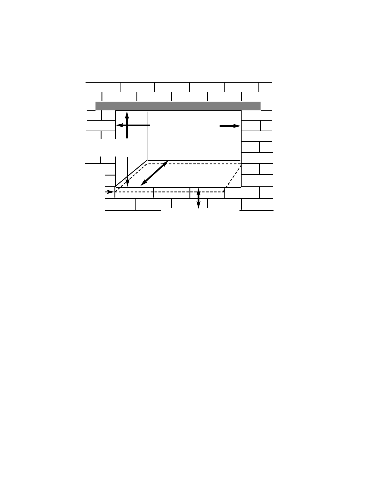
2.2 PREPARATION OF THE COMBUSTION CHAMBER OPENING
(INTO STUDDED WALL) USING A 125MM FLUE LINER.
All combustible parts of the studwork must be set at the distances as shown below
in Fig. 3 & 4.
7
M
inimum 50mm at sides
Minimum 50mm at rear
Combustion Chamber
Dimension “A”
Minimum Width
750mm
Maximum Width
780mm
Dim “A”
Dim “B”
Dimension “B”
Minimum Height
540mm
Maximum Height
545mm
Dim “C”
Dimension “C”
Minimum Depth
383mm
Fig. 3
Fig. 4
A minimum clearance of
100mm is required above
the top of the draught
diverter to combustible
surfaces
Minimum 125mm flue liner required
125mm diameter minimum
flue liner required
20mm Mounting Frame
MINIMUM HEIGHT FROM
FLOOR LEVEL TO
BOTTOM OF OPENING IS
150MM
2.3 PREPARATION OF THE COMBUSTION CHAMBER OPENING
(INTO EXISTING CHIMNEY BREAST)
An opening should be constructed to the following dimensions in the existing
chimney breast. See fig. 5 below
Fig. 5
Adjustable feet are fitted to the combustion chamber to allow fine tuning of it’s
positioning
NOTE : Please ensure that access holes are cut into either the sides or area
above the lintel to allow access to the flue pipe connection if using a flue liner.
Such access holes are also advantageous in installations where a flue liner is not
required as they provide access for servicing purposes.
If installing without a flue liner, please ensure that sufficient depth is available in
the opening to collect a minimum volumetric area of 12 litres (0.012m3) of flue
debris.
Refer to Fig. 1 on page three for dimensions of the flue outlet.
CHECK ANY LOAD BEARING STRUCTURAL ITEMS ARE NOT
AFFECTED BY THE INSTALLATION OF THE PRODUCT. SEE FIG 6
OVERPAGE.
8
Minimum Width 750mm
Maximum Width 765mm
Minimum Height 540mm
Maximum Height 545mm
Minimum Depth 333mm
L
intle must
p
roject 150mm
either side of the
opening if
cutting into an
existing chimney
breast
MINIMUM HEIGHT FROM
FLOOR LEVEL TO
BOTTOM OF OPENING IS
150MM
IMPORTANT
ENSURE PLATFORM
FOR SUPPORTING
PRODUCT IS
APPROXIMATELY 30MM
BELOW THE BOTTOM
OF THE OPENING TO
PREVENT A GAP AT
BOTTOM OF THE TRIM
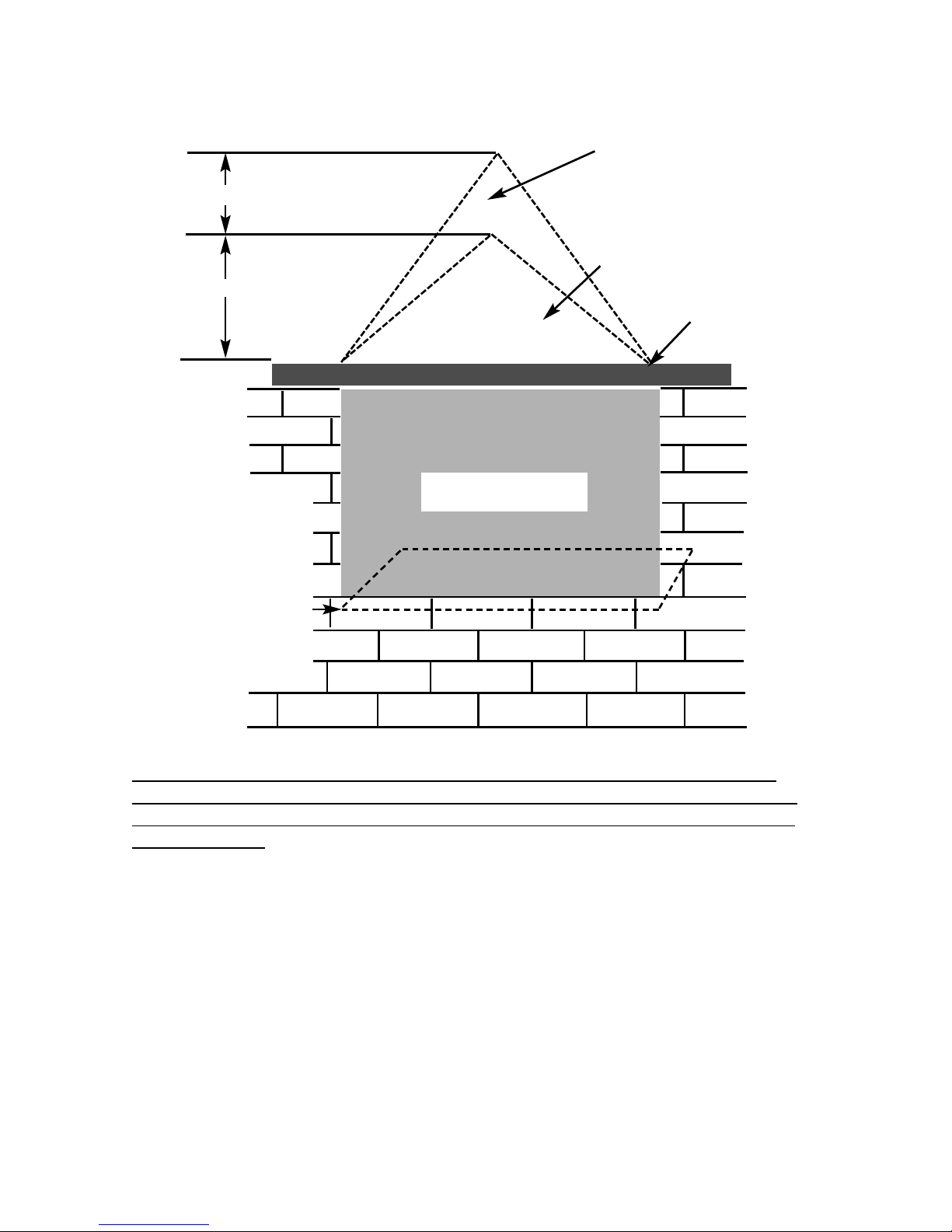
Fig. 6
If fitting without a flue liner, ensure a minimum clearance of 50mm is available
around the semi- circular section of the flue termination to any surface within the
chimney structure. - See page 3, Fig. 1 for more information on clearance to the
flue termination.
The opening needs to be sufficient to accomodate the combustion chamber. To
support the wall above the opening, a suitable lintel must be inserted across the
top of the opening. The lintel could be either pre-cast concrete or steel - Catnic
CN52 or CN 46 could be used, depending upon the inner wall thickness. Before
proceeding with the installation of the fire, an assessment of the area immediately
above the fire is required, see Fig. 6 above. If there is no existing openings within
either triangle, proceed with forming the opening. However, if opening or beams
occur within either triangle, then you should seek specialist advice from a
structural engineer or consider relocating the proposed position of the firebox.
9
400mm interactive area
6
00mm load triangle
T
he Interactive Zone -
O
penings, beams or joists within
this area need to be assessed.
L
oad triangle - No beam or
opening permissible within this
area
Lintel
e.g. 750mm x 75mm
Proposed Opening in
Chimney Breast
IMPORTANT
ENSURE PLATFORM FOR
SUPPORTING PRODUCT IS
APPROXIMATELY 30MM
BELOW THE BOTTOM OF
THE OPENING TO PREVENT
A GAP AT BOTTOM OF THE
TRIM
 Loading...