

Kinder Nevada Powerflue KCPC00MN Installation & Maintenance Instructions Manual

Nevada Powerflue
DECORATIVE FUEL EFFECT POWERFLUE GAS
FIRE
Installation & Maintenance Instructions
Hand these instructions to the user
Model No. KCPC00MN is for use on Natural Gas (G20) at a supply
pressure of 20 mbar in G.B. / I.E.

CONTENTS
Section 1
1.0 Appliance Information 3
1.1 Conditions of Installation 4
1.2 Flue Terminal Position 5
1.3 Fireplace / surround suitability 6
1.4 Fire place opening / catchment space 6
1.5 Shelf Position 6
1.6 Installation Types 7-9
1.7 Hearths 9
1.8 Spillage Monitoring System 9
Section 2 Installation of Fire
2.1 Unpacking the fire 10
2.2 Marking the Flue Pipe Opening 10
2.3 Marking the Fan Unit Recess on the Outer Wall 11-17
2.4 Making the Electrical Connections 18
2.5 Gas tightness and Inlet pressure 19
Section 3 Assembling Fuel Bed and Commissioning
3.1 Assembling the ceramics and fuel bed 20-24
3.2 Lighting the appliance 25
3.3 Checking for clearance of combustion 26
Information and Requirements
& Fitting the fire box
products
PAGE
Section 4 Maintenance
4.1 Removal of the Burner Assembly 27
4.2 Removal of the Piezo Igniter 27
4.3 Removal of the Control Tap 28
4.4 Removal of the Thermocouple 28
4.5 Removal of the Solenoid 28-29
Spare Parts Shortlist
This appliance is manufactured by :CFM Europe Ltd.
Trentham Lakes,
Stoke-on-Trent,
ST4 4TJ
2
29

SECTION 1
INFORMATION AND REQUIREMENTS
1.0 APPLIANCE INFORMATION
Model KCPC00MN
Gas Type G20
Main injectors (2 off) Size 235
Pilot Type S.I.T. Oxystop NG 9022
Max. Gross Heat Input : 6.5 kW
Min. Gross Heat Input : 4.2 kW
Cold Pressure : 20.0 +/-1.0 mbar
Ignition : Push-button Piezo
Supply Voltage : 230V a.c.
Supply Frequency : 50 Hz
Supply Fuse : 3Amp (Fixed Fused Spur) to BS 1362
IP Rating : IP 44
Electrode Spark Gap : 4.0mm
Packed Weight : 12 kg
Fan Unit Packed Weight : 15 kg
Fire box Dimensions (with trim’s fitted)
Nevada Models
Width : (with standard trim, no spacer) 470mm
Height : (with standard trim, no spacer) 586mm
Depth : (overall-without fender) 155mm
Depth : (overall-with spacer fitted) 105mm
Gas Connection :
8mm Compression
3
(Supplied with fire)

INSTALLATION REQUIREMENTS
1.1 CONDITIONS OF INSTALLATION
It is the law that all gas appliances are installed only by a CORGI Registered
Installer
(Installation and Use) Regulations 1998 as amended. Failure to install appliances
correctly could lead to prosecution. It is in your own interest and that of safety to
comply with the law.
The installation must also be in accordance with all relevant parts of the Local and
National Building Regulations where appropriate, the Building Regulations
(Scotland Consolidation) issued by the Scottish Development Department, and all
applicable requirements of the following British Standard Code of Practice.
1. B.S. 5871 Part 3 Installation of Decorative Fuel Effect Gas Fires
2. B.S. 6891 Installation of Gas Pipework
3. B.S. 5440 Parts 1 & 2 Installation of Flues and V
4. B.S. 1251 Open fire place components
5. B.S. 6461 Part 1 Installation of Chimneys and flues
6. I.S. 813 : 1996 Domestic Gas Installation (Republic of Ireland)
No purpose made additional ventilation is normally required for this
appliance, when installed in G.B. When Installing in I.E. please consult
document I.S. 813 : 1996 Domestic Gas Installation, which is issued by the
National Standards Authority of Ireland. If installing in Northern Ireland,
please consult local building regulations. Any purpose made ventilation
must be checked periodically to ensure that it is free from obstruction.
, in accordance with these installation instructions and the Gas Safety
entilation
4
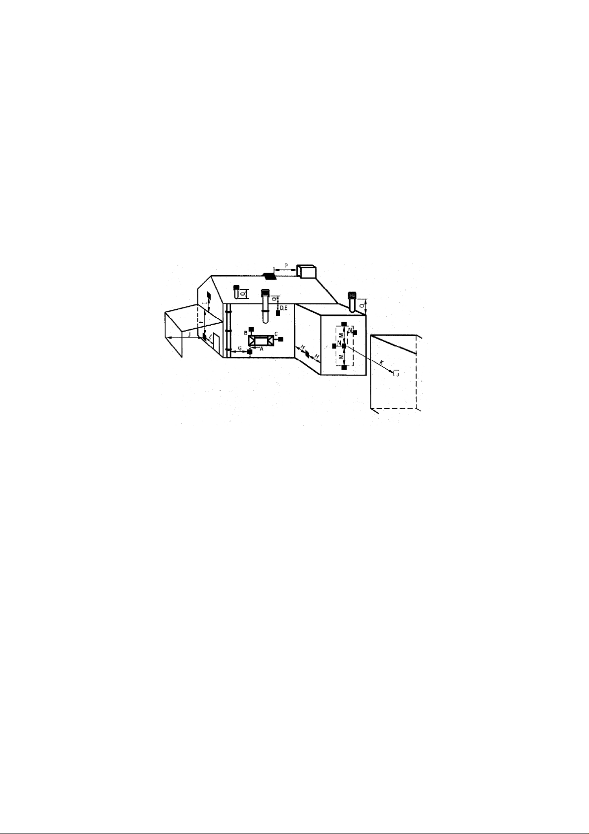
1.2 FLUE TERMINAL POSITION
The minimum acceptable dimensions from the flue terminal to obstructions and
ventilation openings are shown below in fig. 1 and listed in the table (fig. 2 below)
IT IS IMPORTANT THAT THE POSITION OF THE FLUE ALLOWS THE FREE
PASSAGE OF AIR ACROSS IT AT ALL TIMES.
Fig. 1
Fig. 2
DIMENSION TERMINAL POSITION MINIMUM DIMENSION
A Directly below an opening, air brick, 300mm (12 in.)
opening window
B Above an opening, air brick, 300mm (12 in.)
opening window
C Horizontally to an opening, air brick, 300mm (12 in.)
opening window etc.
D Below gutters, soil pipes or drain pipes 75mm (3 in.)
E Below eaves 200mm (8 in.)
F Below balconies or car port roof 200mm (8 in.)
G From a vertical drain pipe or soil pipe 150mm (6 in.)
H From an internal or external corner 200mm (8 in.)
I Above ground roof or balcony level 300mm (12 in.)
J From a surface facing the terminal 600mm (24 in.)
K From a terminal facing the terminal 1200m (48 in.)
L From an opening in the car port 1200m (48 in.)
M Vertically from a terminal on the same wall 1500mm (59 in.)
N Horizontally from a terminal on the 300mm (12 in.)
same Wall
O From the wall on which the terminal is mounted 50mm (2 in.)
P From a vertical structure on the roof N/A
Q Above intersection with roof 150mm
5

1.3 FIREPLACE / SURROUND SUITABILITY
The fire must only be installed on a hearth it must not be installed directly onto
carpet or other combustible floor materials.
The fire is suitable for fitting to
non-combustible fire place surrounds and proprietary fire place surrounds with a
temperature rating of at least 150oc. If a heating appliance is fitted directly against
a wall without the use of a fire surround or fire place all combustible material must
be removed from behind the trim. Soft wall coverings such as blown vinyl, wall
paper etc. could be affected by the rising hot air and scorching and/or discoloration
may result. Due consideration should be made to this when installing or
decorating.
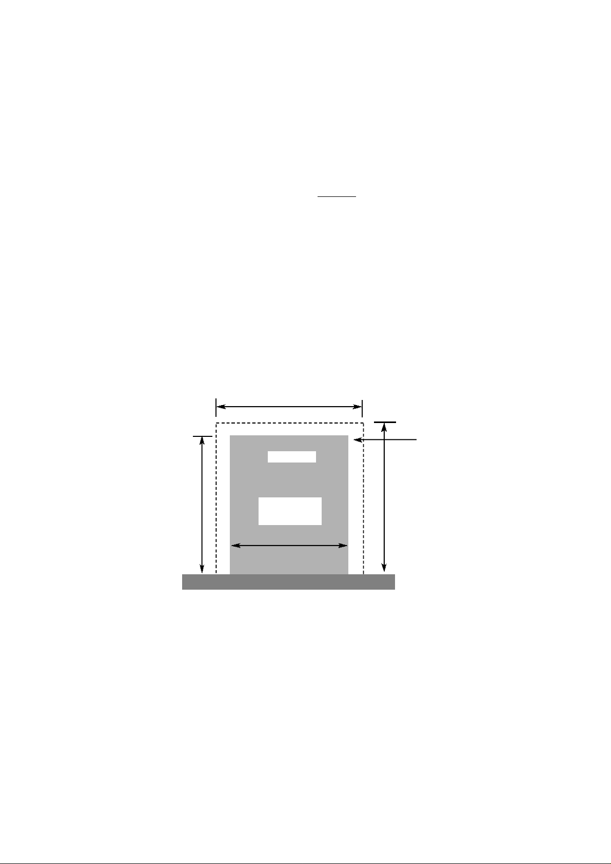
1.4 FIRE PLACE OPENING
The front opening of the fire place must be between 330 and 430 mm wide, and
between 550 and 565mm high. If the opening exceeds these dimensions then a
surround must be constructed from suitable non-combustible material to produce a
correct size opening. Any surround must be suitably sealed to the fire place to
prevent leakage. See below in fig.3
520mm Minimum
Fig. 3
Minimum Flat
Sealing Area
Fire Opening
550mm Minimum
565mm Maximum
330mm Minimum
430mm Maximum
610mm Minimum
1.5 SHELF POSITION
The fire may be fitted below a combustible shelf providing there is a minimum
distance of 200mm above the top of the fire and the shelf does not project more
than 150mm. If the shelf overhangs more than 150mm the distance between the
fire and the shelf must be increased by 15mm for every 25mm of additional
overhang over 150mm.
6
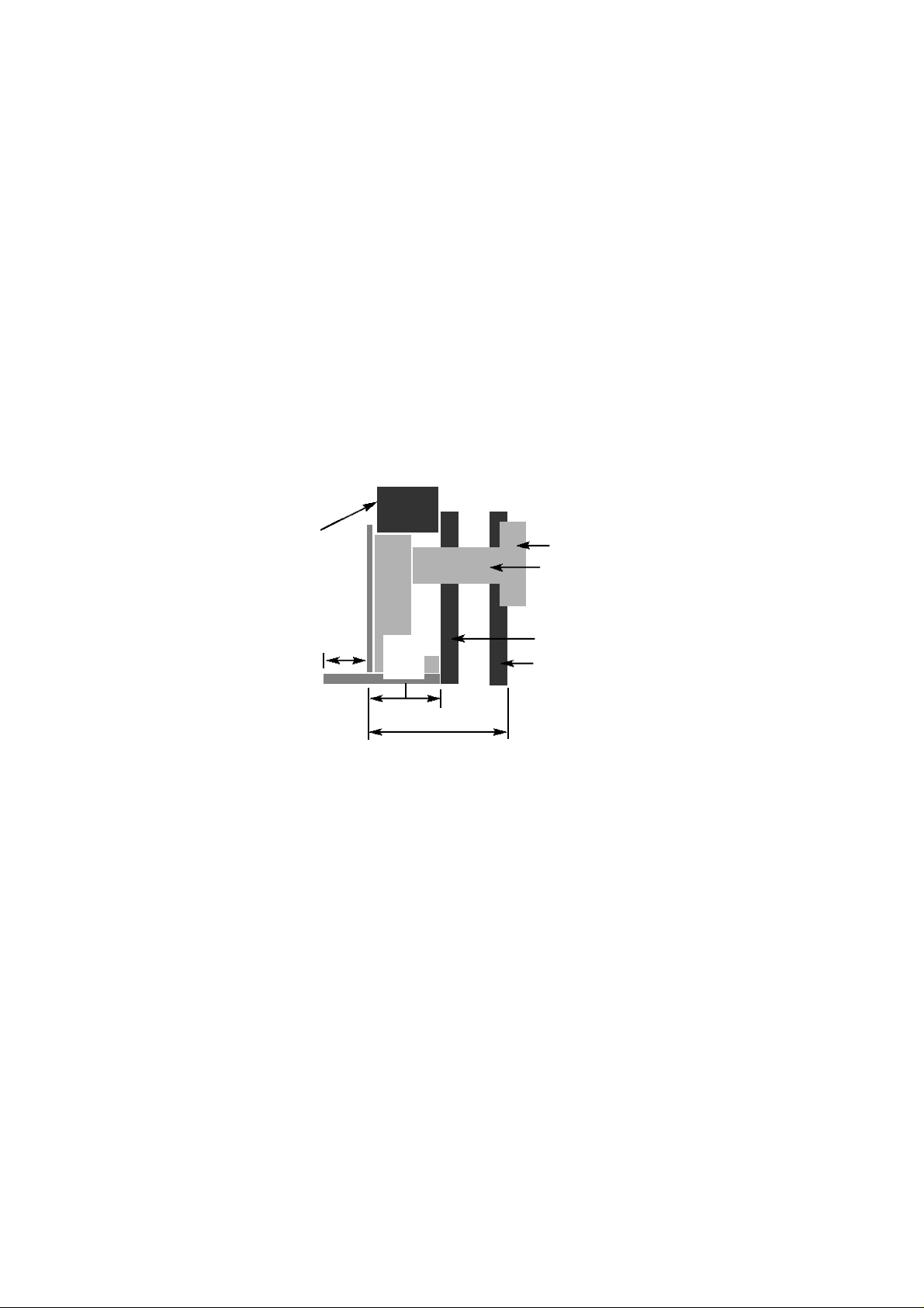
1.6 INSTALLATION TYPES
This fire can be fitted against an outside facing facing flat wall surface or into a
fireplace opening cut into the wall.
When fitting the fire in front of the inner cavity wall
, the distance between the
mounting face of the fire and the rear face of the firebox must be a minimum of
170mm, a false chimney breast or fireplace surround should be constructed.
The
firebox must then be secured into the fireplace using the method described in
section 2. Any combustible material must be removed from the the area around
the firebox flange. In all installations, ensure that there is no structural damage to
the property or the damp course. See fig. 4 below
Fig. 4
False Chimney
Breast / Fireplace
Minimum Hearth
Forward Projection
300mm
155mm
All
Models
550mm Maximum
Fan Unit
Flue Pipe
Inner Cavity Wall
Outer Cavity Wall
When fitting the fire into a cavity wall, this requires the opening of the inner leaf
of brickwork, to recess the firebox into. The opening needs to be sufficient to
accomodate the firebox. T
o support the wall above the hole, a suitable lintel must
be inserted across the top of the opening. If fitting the appliance into a cavity wall,
a lintel 750mm long having a thickness of 75mm with a height of the inner wall
should be used.
The lintel could be either pre-cast concrete or steel - Catnic
CN52 or CN 46 could be used, depending upon the inner wall thickness. Before
proceeding with the installation of the fire, an assessment of the area immediately
above the fire is required, see Fig. 5 overpage. If there is no existing openings
within either triangle, proceed with forming the opening. However, if opening or
beams occur within either triangle, then you should seek specialist advice from a
structural engineer or consider relocating the proposed position of the firebox.
7

Fig. 5
400mm interactive
area
600mm load
triangle
The Interactive Zone Openings, beams or joists within
this area need to be assessed.
Load triangle - No beam or
opening permissible within this
area
Lintel
e.g. 750mm x 75mm
Opening Height
550mm Minimum
565mm Maximum
50mm Minimum Hearth Thickness
Firebox recess in
wall
Opening Width
330mm Minimum
430mm Maximum
To proceed with the installation when the above stated criteria have been
satisfied :-
Mark out where possible, centrally beneath a block joint where the lintel is to be
fitted. Unless lime mortar has been used it will be necessary to drill four holes
with a masonary drill, then use a mechanical cutter such as a “shark saw” to cut
out the correct size of slot in the inner leaf of brickwork for the lintel you have
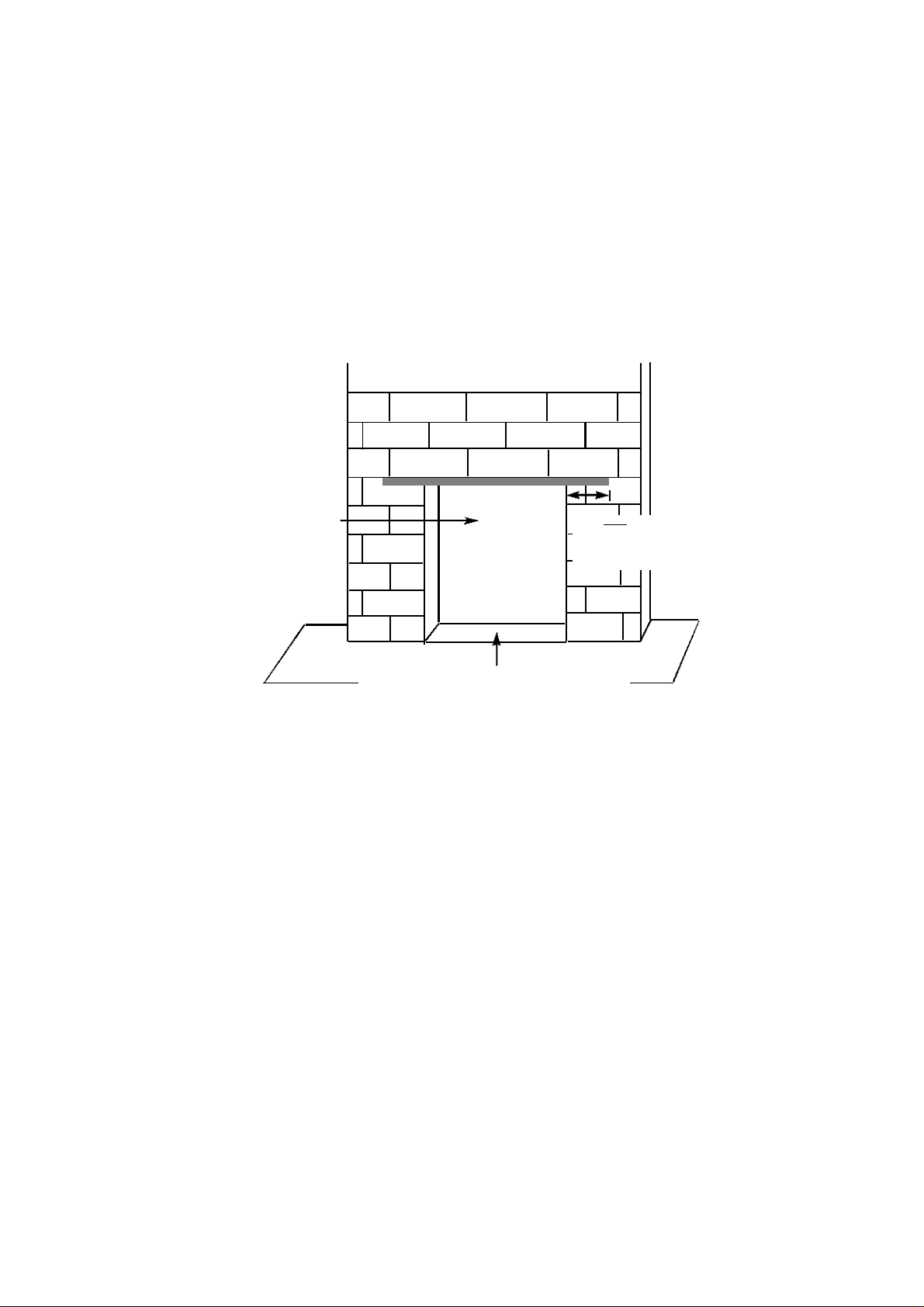
chosen to install. See fig. 6 below.
Fig. 6
Fit the lintel, ensure that it is bedded on mortar. Do not bed on a dry bed.
Then remove all debris from the cavity and construct the opening to the minimum /
maximum opening sizes as shown overpage (fig. 7) and in section 1.4, (fig. 3)
8
Remove any combustible material from within the area of the opening. No
combustible material can be allowed to come into contact with any area of the
appliance.
Fig. 7
Opening Sizes Width :330mm Minimum
430mm Maximum
Opening sizes Height :550mm Minimum
565mm Maximum
Ensure that the recess that is cut is to the required
dimensions and is screed level so that the firebox will
sit level within the recess.
Lintel must project
Minimum of 150mm
each side of the
opening
1.7 HEARTHS
This appliance must only be installed on to a concrete or non-combustible hearth.
The hearth material must be a minimum thickness of 12mm with the top surface at
least 50mm above the floor.
The hearth must be fitted symmetrically about the fire
opening and have a minimum width of 760mm and a minimum projection of
300mm forwards from the fire opening.
1.8 SPILLAGE MONITORING SYSTEM
This appliance is fitted with an atmosphere sensing spillage monitoring system in
the form of an oxygen sensing burner. This is designed to shut the fire off in the
event of a partial or complete blockage of the flue causing a build up of
combustion products in the room in which the fire is operated. The following are
important warnings relating to this spillage monitoring system
1)
The spillage monitoring system must not be adjusted by the installer
:-
.
2) The spillage monitoring system must not be put out of operation.
3) When the spillage monitoring system is exchanged only a complete original
manufacturers part may be fitted.
9
 Loading...