

Kinder Kalahari SC Powerflue, KPFC00SN, KPFC00SP Installation And Maintenance Instructions Manual

Kalahari SC
Powerflue
DECORATIVE FUEL EFFECT
POWERFLUE GAS FIRES
Installation and Maintenance Instructions
Hand these instructions to the user
Model No. KPFC00SN is for use on Natural Gas (G20) at a supply
pressure of 20 mbar in G.B. / I.E.
Model No. KPFC00SP is for use on Propane Gas (G31) at a supply
pressure of 37 mbar in G.B. / I.E.

CONTENTS
Section 1 Information and Requirements PAGE
1.0 Appliance Information 3
1.1 Conditions of Installation 4
1.2 Flue Terminal Position 4
1.3 Fireplace / Surround Suitability 5
1.4 Fireplace Opening 6
1.5 Shelf Position 6
1.6 Installation Types 6-7
1.7 Hearths 7-9
1.8 Spillage Monitoring System 10
Section 2 Installation of Fire
2.1 Unpacking the fire 11
2.2 Marking the Firebox Recess 11
2.3 Fitting the Fan Unit / Firebox 12-20
2.4 Making the Electrical Connection 21
2.5 Making the Gas Connection 21
2.6 Making the Solenoid / Wiring Loom Connection 22
2.7 Final Fitting of the Fan Unit 22-23
2.8 Gas Tightness & Inlet Pressure 24
Section 3 Assembling Fuel Bed and Commissioning
3.1A Assembling the ceramics and fuel bed (Pebble Fuelbed) 24-27
3.1B Assembling the ceramics and fuel bed (Coal Fuelbed) 28-31
3.2 Lighting the appliance 32
3.3 Checking for clearance of combustion 33
products
Section 4 Maintenance
4.1 Removal of the Burner Assembly 34-35
4.2 Removal of the Battery Ignitor 35
4.3 Replacement of the Battery 35
4.4 Removal of the Pilot Assembly 35
4.5 Replacement of the Control Cable 36-37
Parts Shortlist 37
This appliance is manufactured by:BFM Europe Ltd,
Trentham Lakes,
Stoke-on-Trent, ST4 4TJ
2

SECTION 1
INFORMATION AND REQUIREMENTS
1.0 APPLIANCE INFORMATION
Model KPFC00SN KPFC00SP
Gas Type G20 G31
Main injectors (2 off) Size 260 Size 85
Pilot Type Copreci Copreci
Single Flame Single Flame
21100 / 162 21100 / 167
Max. Gross Heat Input : 6.9 kW
Min. Gross Heat Input : 4.2 kW
Cold Pressure : 19.0 +/-1.0 mbar 36.0 +/-1.0 mbar
Ignition : 1.5V Battery Generator
Supply Voltage : 230V a.c.
Supply Frequency : 50Hz
Supply Fuse : 3 Amp to BS 1362
Power Input : 90W
IP Rating : IP23
Electrode Spark Gap 4.5mm
Packed Weight (without fender) 24kg
Fire box Dimensions (with trim’s fitted)
Kalahari Models
Width : (with standard trim, no spacer) 470mm
Height : (with standard trim, no spacer) 586mm
Depth : (overall-without fender) 170mm
Depth : (overall-with spacer fitted) 120mm
Gas Connection : 8mm Compression (Supplied with fire)
3

INSTALLATION REQUIREMENTS
1.1 CONDITIONS OF INSTALLATION
It is the law that all gas appliances are installed in accordance with the rules in
force only by a CORGI Registered Installer in G.B, in accordance with these
installation instructions and the Gas Safety (Installation and Use) Regulations
1998 as amended. Failure to install appliances correctly could lead to
prosecution. It is in your own interest and that of safety to comply with the law.
The installation must also be in accordance with all relevant parts of the Local and
National Building Regulations where appropriate, the Building Regulations
(Scotland Consolidation) issued by the Scottish Development Department, and all
applicable requirements of the following British Standard Code of Practice.
1. B.S. 5871 Part 3 Installation of Decorative Fuel Effect Gas Fires
2. B.S. 6891 Installation of Gas Pipework
3. B.S. 5440 Parts 1 & 2 Installation of Flues and Ventilation
4. B.S. 1251 Open fire place components
5. B.S. 715 Metal flue pipes for gas appliances
6. B.S. 6461 Part 1 Installation of Chimneys and flues
7. I.S. 813 : 1996 Domestic Gas Installation (Republic of Ireland)
No purpose made additional ventilation is normally required for this
appliance, when installed in G.B. When Installing in I.E. please consult
document I.S. 813 : 1996 Domestic Gas Installation, which is issued by the
National Standards Authority of Ireland. If installing in Northern Ireland,
please consult local building regulations. Any purpose made ventilation
must be checked periodically to ensure that it is free from obstruction.
4
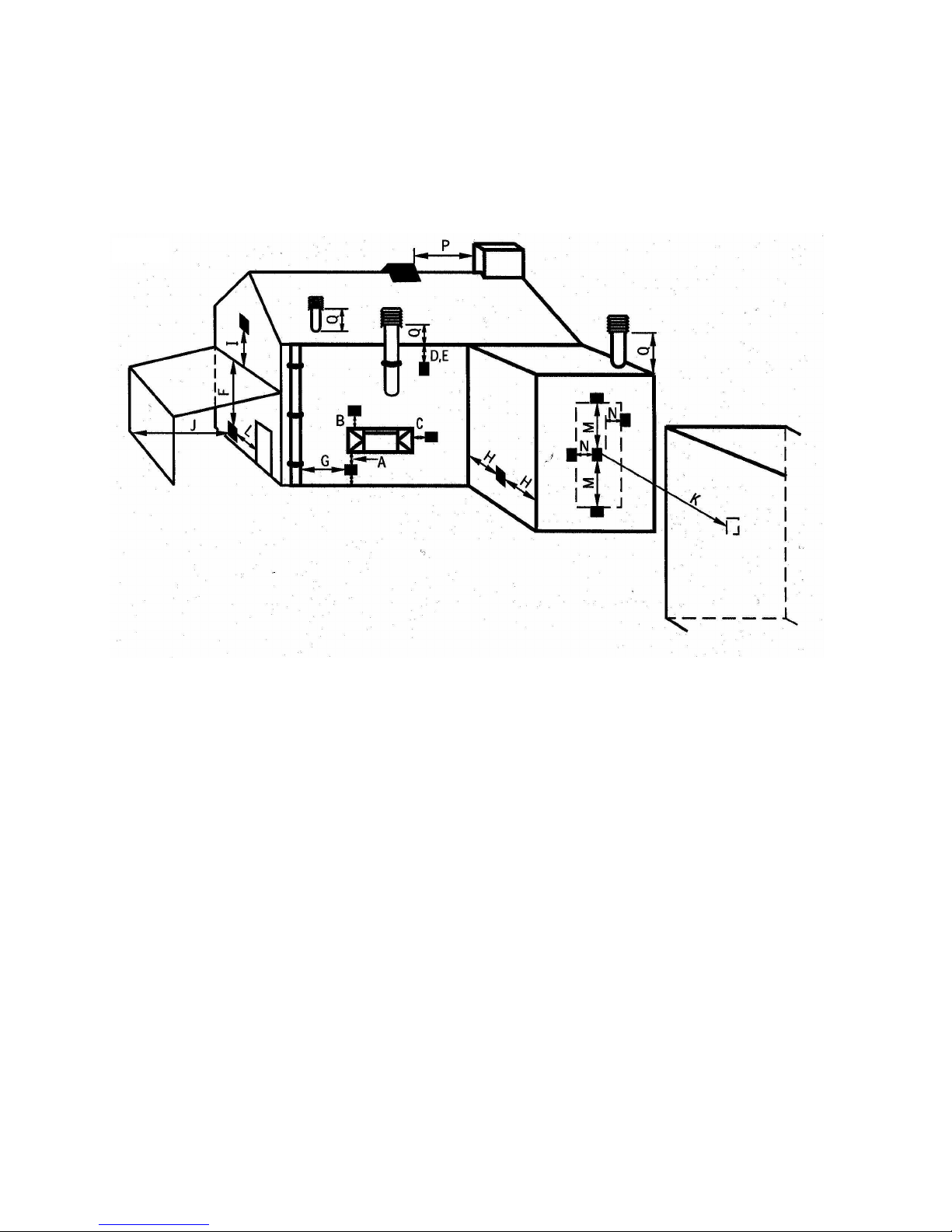
1.2 FLUE TERMINAL POSITION
The minimum acceptable dimensions from the flue terminal to obstructions and
ventilation openings are shown below in fig. 1 and listed in the table (Fig. 2 below)
IT IS IMPORTANT THAT THE POSITION OF THE FLUE ALLOWS THE FREE
PASSAGE OF AIR ACROSS IT AT ALL TIMES.
DIMENSION TERMINAL POSITION MINIMUM DIMENSION
A Directly below an opening, air brick, 300mm (12 in.)
opening window
B Above an opening, air brick, 300mm (12 in.)
opening window
C Horizontally to an opening, air brick, 300mm (12 in.)
opening window etc.
D Below gutters, soil pipes or drain pipes 75mm (3 in.)
E Below eaves 200mm (8 in.)
F Below balconies or car port roof 200mm (8 in.)
G From a vertical drain pipe or soil pipe 150mm (6 in.)
H From an internal or external corner 200mm (8 in.)
I Above ground roof or balcony level 300mm (12 in.)
J From a surface facing the terminal 600mm (24 in.)
K From a terminal facing the terminal 1200m (48 in.)
L From an opening in the car port 1200m (48 in.)
M Vertically from a terminal on the same wall 1500mm (59 in.)
N Horizontally from a terminal on the 300mm (12 in.)
same Wall
O From the wall on which the terminal is mounted 50mm (2 in.)
P From a vertical structure on the roof N/A
Q Above intersection with roof 150mm
5
Fig. 1
Fig. 2
1.3 FIREPLACE / SURROUND SUITABILITY
The fire must only be installed on a hearth it must not be installed directly onto
carpet or other combustible floor materials.
The fire is suitable for fitting to non-combustible fire place surrounds and propri-
etary fire place surrounds with a temperature rating of at least 150oc.
If a heating appliance is fitted directly against a wall without the use of a fire
surround or fire place all combustible material must be removed from behind
the trim. Soft wall coverings such as blown vinyl, wall paper etc. could be
affected by the rising hot air and scorching and/or discoloration may result.
Due consideration should be made to this when installing or decorating.
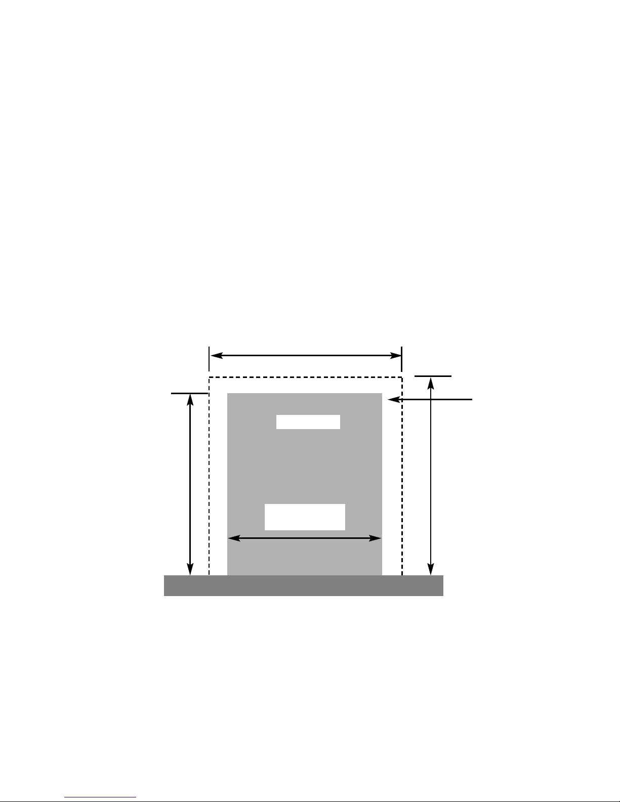
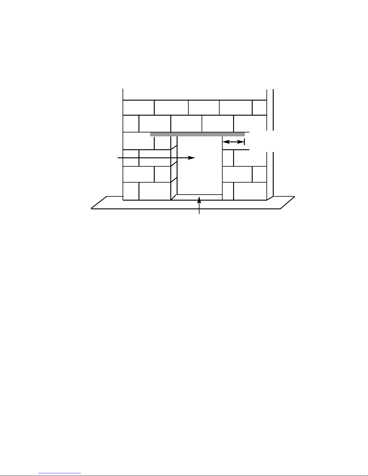
1.4 FIRE PLACE OPENING
The front opening of the fire place must be between 375 and 440 mm wide, and
between 550 and 570mm high. If the opening exceeds these dimensions then a
surround must be constructed from suitable non-combustible material to produce a
correct size opening. Any surround must be suitably sealed to the fire place to
prevent leakage. See below in fig.3
1.5 SHELF POSITION
The fire may be fitted below a combustible shelf providing there is a minimum
distance of 200mm above the top of the fire and the shelf does not project more
than 150mm. If the shelf overhangs more than 150mm the distance between the
fire and the shelf must be increased by 15mm for every 25mm of additional overhang over 150mm.
Fire Opening
375mm Minimum
440mm Maximum
610mm
Minimum
520mm Minimum
Fig. 3
550mm Minimum
570mm Maximum
Minimum Flat
Sealing Area
6
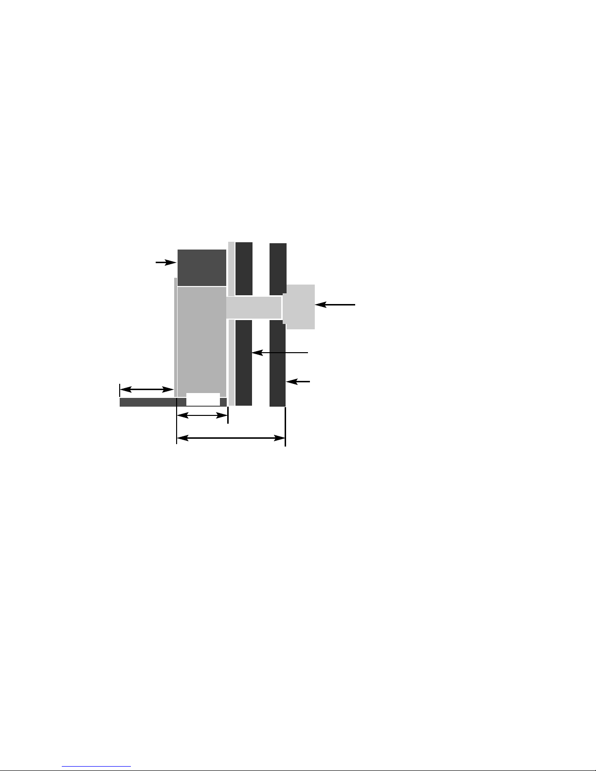
1.6 INSTALLATION TYPES
This fire can be fitted against an outside facing facing flat wall surface or into a
fireplace opening cut into the wall.
When fitting the fire in front of the inner cavity wall, the distance between the
mounting face of the fire and the rear face of the firebox (170mm nominally),
a false chimney breast or fireplace surround should be constructed. The firebox
must then be secured into the fireplace using the method described in section 2.
Any combustible material must be removed from the the area around the firebox
flange. In all installations, ensure that there is no structural damage to the
property or the damp course. See fig. 4 below
When fitting the fire into a cavity wall, this requires the opening of the inner leaf
of brickwork, to recess the firebox into. The opening needs to be sufficient to
accomodate the firebox. To support the wall above the hole, a suitable lintel must
be inserted across the top of the opening. If fitting the appliance into a cavity wall,
a lintel 750mm long having a thickness of 75mm with a height of the inner wall
should be used. The lintel could be either pre-cast concrete or steel - Catnic
CN52 or CN 46 could be used, depending upon the inner wall thickness. Before
proceeding with the installation of the fire, an assessment of the area immediately
above the fire is required, see Fig. 5 overpage. If there is no existing openings
within either triangle, proceed with forming the opening. However, if opening or
beams occur within either triangle, then you should seek specialist advice from a
structural engineer or consider relocating the proposed position of the firebox.
7
170mm
Fan Unit
Outer Cavity Wall
Inner Cavity Wall
False
Chimney /
Fireplace
Maximum Installation Depth From Mounting Face of Fire
Surround to Outer Face of Cavity Wall = 870mm
Minimum Installation Depth From Mounting Face of Fire
Surround to Outer Face of Cavity Wall = 320mm
Minimum Hearth
Forward Projection
300mm
Fig. 4
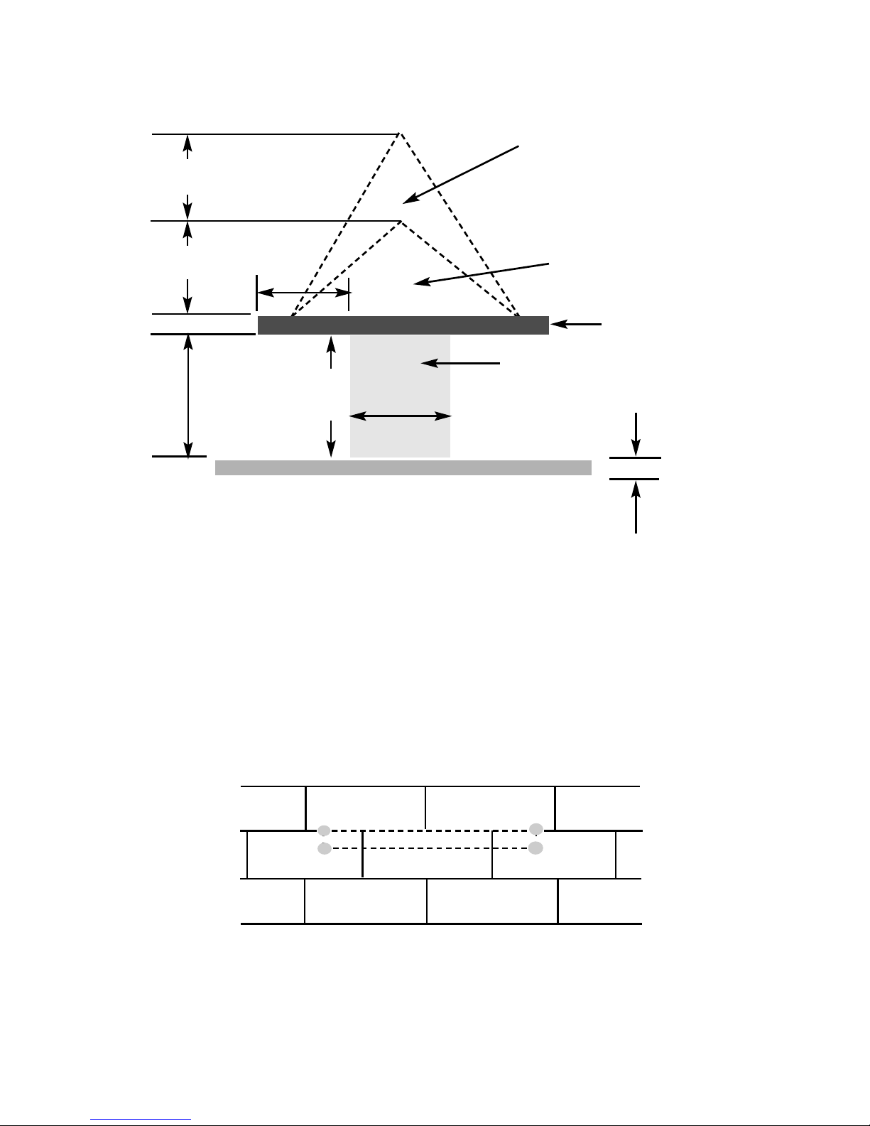
Fig. 5
To proceed with the installation when the above stated criteria have been
satisfied :-
Mark out where possible, centrally beneath a block joint where the lintel is to be
fitted. Unless lime mortar has been used it will be necessary to drill four holes
with a masonary drill, then use a mechanical cutter such as a “shark saw” to cut
out the correct size of slot in the inner leaf of brickwork for the lintel you have
chosen to install. See fig. 6 below.
Fig. 6
Fit the lintel, ensure that it is bedded on mortar. Do not bed on a dry bed.
Then remove all debris from the cavity and construct the opening to the minimum /
maximum opening sizes as shown overpage (fig. 8) and in section 1.4, (fig. 3)
8
The Load Triangle - No
Beam or opening permissible
in this area
600mm load
t
riangle
400mm
interactive area
50mm Minimum
Hearth Height
Opening Width
375mm Minimum
440mm Maximum
Opening Height
550mm Minimum
570mm Maximum
Lintel
e.g. 750mm x 75mm
T
he Interactive Zone - Openings,
beams or joists within this area
n
eed to be assessed.
Firebox recess in wall
Remove any combustible material from within the area of the opening. No
combustible material can be allowed to come into contact with any area of the
appliance.
Fig. 7
1.7 HEARTHS
This appliance must only be installed on to a concrete or non-combustible hearth.
The hearth material must be a minimum thickness of 12mm with the top surface at
least 50mm above the floor. The hearth must be fitted symmetrically about the fire
opening and have a minimum width of 760mm and a minimum projection of
300mm forwards from the fire opening. If the black spacer frame is used, the
hearth projection forward from the fireplace opening will require to be 350mm.
9
Opening Sizes Width :375mm Minimum
440mm Maximum
Opening Sizes Height
550mm Minimum
570mm Maximum
Lintel must project
Minimum 150mm each
side of opening
Ensure that the recess of the firebox is screed level so the firebox
will sit level within the recess

1.8 SPILLAGE MONITORING SYSTEM
This appliance is fitted with an atmosphere sensing spillage monitoring system in
the form of an oxygen sensing pilot. This is designed to shut the fire off in the
event of a partial or complete blockage of the flue pipe causing a build up of
combustion products in the room in which the fire is operated. The following are
important warnings relating to this spillage monitoring system :-
1) The spillage monitoring system must not be adjusted by the installer.
2) The spillage monitoring system must not be put out of operation.
3) When the spillage monitoring system is exchanged only a complete
original manufacturers part may be fitted. It is not possible to replace
individual parts on the pilot system on this appliance, only a complete
pilot assembly (including the thermocouple) may be fitted.
10
SECTION 2
INSTALLATION OF FIRE
2.1 UNPACKING THE FIRE
Carefully lift the fire out of the carton. Remove the loose item packaging carefully
from the front of the appliance. Check the contents as listed :-
Packing Check List
1off Fire box / burner assembly
1off Boxed fuelbed base, ceramic front rail and 18 synthetic coals
1off Loose items bag.
1off Flue Tube
1off Fan Unit
1off Flue Collar & Seal
1off Cable Fixing Kit
1off each User instruction book and Installation book
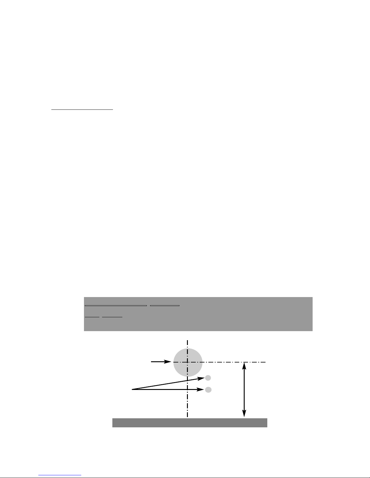
2.2 MARKING THE FIREBOX RECESS
Drill a pilot hole into the outer leaf of brickwork at a height of 482mm from the
hearth level, centrally about the firebox, then using a core drill, drill a hole of
150mm (6 inch) diameter, centrally about the horizontal line drawn above the level
of the hearth, and vertically central to the centre line of the appliance. See fig. 8
below.
NOTE : If the fire is to be fitted against the inner cavity wall, the inner and
outer cavity walls will require drilling.
Fig. 8
11
482mm to
CRS
Hearth
Diameter 150mm
(6 inch)
2 off diameter
25mm holes
IIIIMMMMPPPPOOOORRRRTTTTAAAANNNNTTTTNNNNOOOOTTTTEE
EE
::
DO NOT FIT THIS APPLIANCE FAN UNIT ABOVE
A HEIGHT OF 1.4M FROM GROUND LEVEL
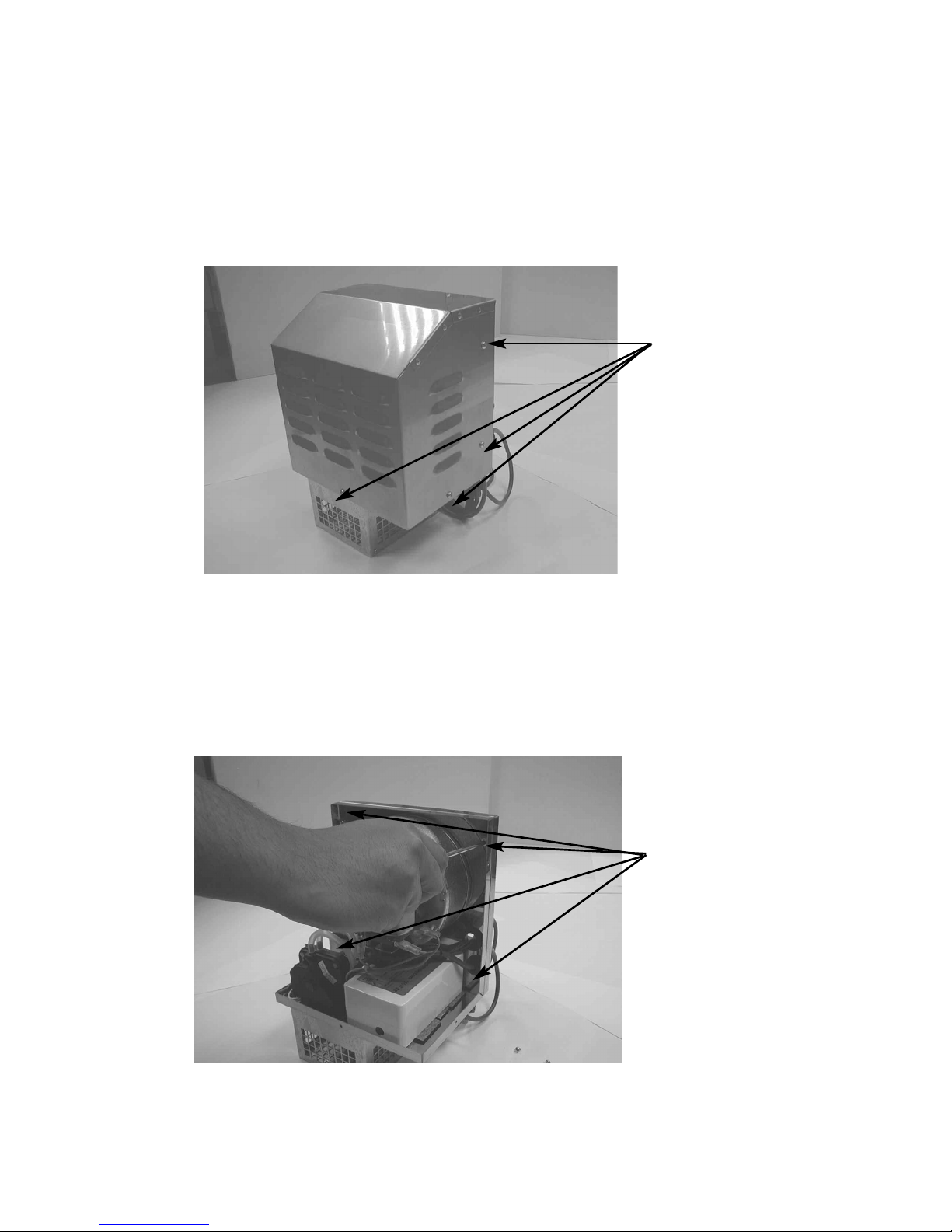
2.3 FITTING THE FAN UNIT / FIREBOX
a) Remove the 7 outer case fixing screws which hold the fan unit cover in
place. See fig. 9 below.
Fig. 9
b) Remove the fan mounting plate from the main body of the fan unit by
removing the four screws from the fan unit as indicated below in fig. 10
Fig. 10
7 off Outer Case
Fixing Screws
4 screws to remove
fan unit from
mounting plate
12
 Loading...