

Kinder Cameo BF, KBFLRN2, Proclaim BF Installation And Maintenance Instructions Manual

Cameo BF
LOG EFFECT BALANCED FLUE ROOM HEATER
Installation and Maintenance Instructions
Hand these instructions to the user
Model No. KHBL**RN is for use on Natural Gas (G20) at a supply pressure of
20 mbar in G.B. / I.E.
** Denotes trim & colour variant

CONTENTS
P
AGE
S
ection 1 Information and Requirements
1.0 Appliance information 3
1.1 Conditions of installation 4
1
.2 Fireplace surround & suitability 4
1.3 Flue terminal position 5
1.4 Shelf position 6
1.5 Hearths 6
1.6 Installation to plastered wall surfaces 6
Section 2 Installation of Fire
2.1 Unpacking the combustion chamber 7
2.2 Preparing the combustion chamber opening (In studded wall) 8
2.3 Preparing the combustion chamber opening (In chimney breast) 9-10
2.4 Installation of the gas supply 11
2.5 Specifying the flue system & components 12-13
2.6 Preparation of the wall 14
2.7 Preparation of the flue hole 15
2.8 Fitting the starter pipe 15-16
2.9 Fitting the flue pipes together 17
2.10 Fitting the flue terminal 18
2.11 Fitting the flue terminal guard 19
2.12 Removal & re-fitting of the glass frame 20
Section 3 Assembling Fuel Bed and Commissioning
3.1 Fitting the fuel bed logset 21-24
3.2 Making the gas conection & checking for gas tightness 24
3.3 Lighting the appliance 25-27
3.4 Removal & re-fitting the Cameo fascia 28
Section 4 Maintenance
4.1 Removal of the burner assembly 29
4.2 Removal of the control valve 29-30
4.3 Removal of the ultrasonic reciever 30
4.4 Removal of the pilot assembly 30-31
4.5 Removal / Replacement of batteries in the Ultrasonic Receiver 31
4.6 Removal / Replacement of the handset battery 31
Model number KHBL**RN manufactured by:-
BFM Europe Ltd, Trentham Lakes, Stoke-on-Trent, Staffordshire, ST4 4TJ
Appliance Efficiency Declaration
The efficiency of this appliance has been measured as specified in
BS EN 613 : 2001 and the result is 76%. The gross calorific value of the fuel has
been used for this efficiency calculation. The test data from which it has been
calculated has been certified by GL Industrial Services UK Ltd. The efficiency
value may be used in the UK Government’s Standard Assessment Procedure
(SAP) for energy rating of dwellings.
2
SECTION 1
INFORMATION AND REQUIREMENTS
1.0 APPLIANCE INFORMATION
Main injector : (1 off) Cat 82 – size 380 (NG)
Pilot Type : S.I.T. 140 Series NG – size 27
Max. Gross Heat Input : 5.5kW
Min. Gross Heat Input : 3.0kW
Gas Rate : 0.512 m3/hr (High)
0.280 m3/hr (Low)
Cold Pressure : G20 20.0+/-1.0 mbar (8.0 +/- 0.4 in w.g.)
Ignition : Integral to gas valve
Electrode Spark Gap : 4.0mm
Packed Weight Combustion Chamber : 32.0 kg (Pack 1 of 2)
Packed Weight Flue Terminal Pack : 16.0 kg (Pack 2 of 2)
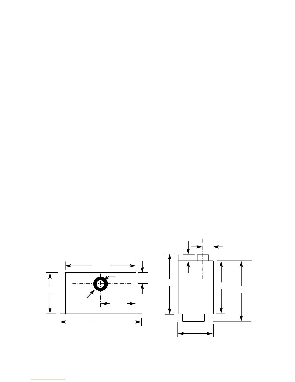
Fig 1
Top View of Combustion Side View of Combustion
Chamber Chamber
3
729 mm
631 mm
316 mm
315mm
150mm
Diameter
128mm
100mm
460mm
420mm
128mm CRS
316mm
375mm
26mm

INSTALLATION REQUIREMENTS
1.1 CONDITIONS OF INSTALLATION
It is the law that all gas appliances are installed only by a GAS SAFE Registered
Installer, in accordance with these installation instructions and the Gas Safety
(Installation and Use) Regulations 1998 as amended. Failure to install appliances
correctly could lead to prosecution. It is in your own interest and that of safety to
comply with the law.
The installation must also be in accordance with all relevant parts of the Local and
National Building Regulations where appropriate, the Building Regulations
(Scotland Consolidation) issued by the Scottish Development Department, and all
applicable requirements of the following British Standard Code of Practice.
1. B.S. 5871 Part 1 Installation of Gas Fires
2. B.S. 6891 Installation of Gas Pipework
3. B.S. 5440 Parts 1 & 2 Installation of Flues and Ventilation
4. I.S 813 : 1996 Domestic Gas Installation, issued by the National Standards
Authority of Ireland.
1.2 FIREPLACE / SURROUND SUITABILITY
The fire must only be installed on a hearth it must not be installed directly onto
carpet or other combustible floor materials.
The fire is suitable for fitting to non-combustible fire place surrounds and
proprietary fire place surrounds with a temperature rating of at least 150oc.
If a heating appliance is fitted directly against a wall without the use of a fire
surround or fire place all combustible material must be removed from behind
the trim. Soft wall coverings such as blown vinyl, wall paper etc. could be
affected by the rising hot air and scorching and/or discoloration may result.
Due consideration should be made to this when installing or decorating.
4

1.3 FLUE TERMINAL POSITION
The minimum acceptable dimensions from the flue terminal to obstructions
and ventilation openings are shown below and listed in the table
It is important that the position of the flue allows the free passage of air
across it at all times. The minimum acceptable space from the flue terminal
to obstructions and ventilation openings are specified below (Fig. 2)
Fig. 2
DIMENSION TERMINAL POSITION MINIMUM DIMENSION
A Directly below an opening, air brick, 300mm (12in)
opening window
B Above an opening, air brick, 300mm (12in)
opening window
C Horizontally to an opening, air brick,
opening window etc.
D Below gutters, soil pipes or drain pipes 300mm (12in)
E Below eaves 300mm (12in)
F Below balconies or car port roof 600mm (12in)
G From a vertical drain pipe or soil pipe 300mm (12in)
H From an internal or external corner 600mm (24in)
I Above ground roof or balcony level 300mm (12in)
J From a surface facing the terminal 600mm (24in)
K From a terminal facing the terminal 600mm (24in)
L From an opening in the car port 1200m (48in)
M Vertically from a terminal on the same wall 1500mm(59in)
N Horizontally from a terminal on the 300mm (12in)
same Wall
O NOT APPLICABLE N/A
P NOT APPLICABLE N/A
Q NOT APPLICABLE N/A
5
1.4 SHELF POSITION
The fire may be fitted below a combustible shelf providing there is a minimum
distance of 300mm above the top of the fire and the shelf does not project more
than 150mm. If the shelf overhangs more than 150mm the distance between the
fire and the shelf must be increased by 15mm for every 25mm of additional
overhang over 150mm.
1.5 HEARTHS
This appliance does not require the fitting of a hearth that projects in front of it
when installed into a recess in either an existing chimney breast or a studded wall.
The appliance must however stand on a non-combustible base that is a minimum
thickness of 12mm.
1.6 INSTALLATION TO PLASTERED WALL SURFACES
If installing to a plastered wall, all material must be removed from the 50mm area
surrounding the combustion chamber opening, and replaced with non-combustible
material, such as marble or granite, to prevent plaster cracking. See Fig. 3 below
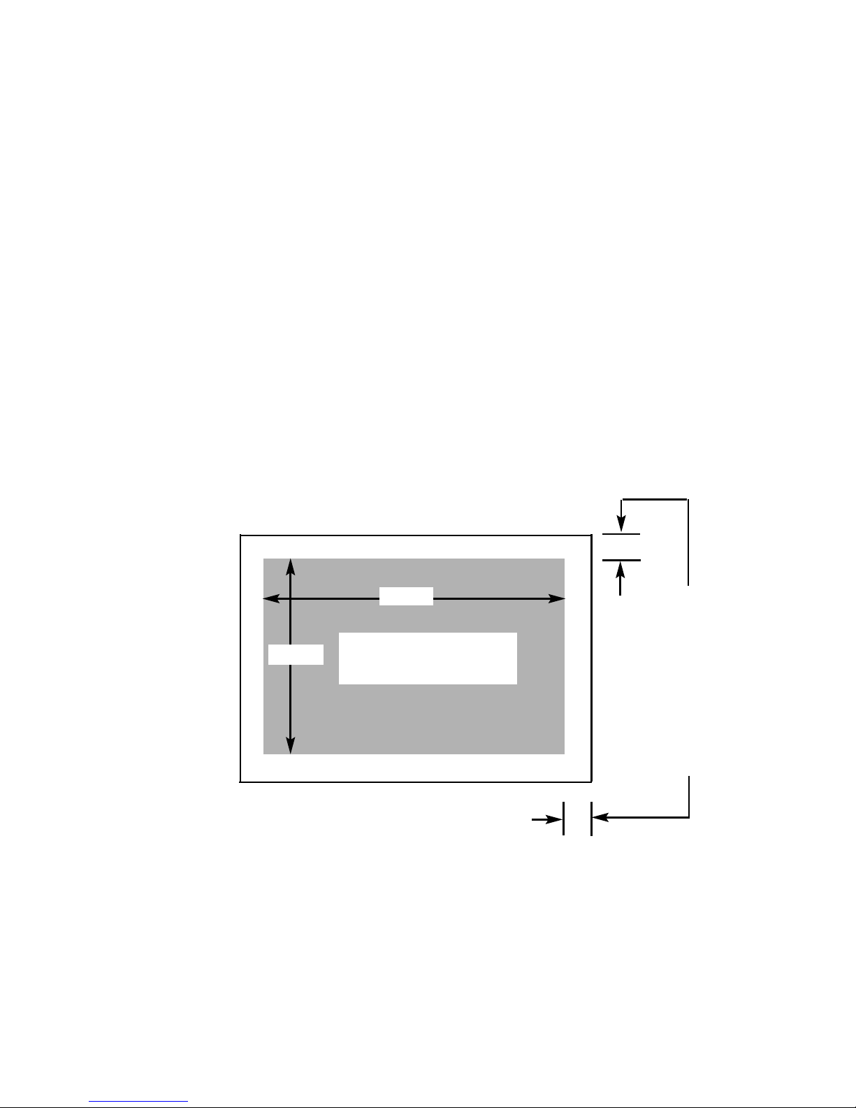
Fig. 3
6
Combustion Chamber
Opening in Studded Wall or
Existing Chimney Breast
635mm
465mm
Minimum 50mm
of material to be
removed all
round perimeter
of combustion
chamber and
replaced with
marble, granite
or other noncombustible
material

SECTION 2
INSTALLATION OF FIRE
2.1 UNPACKING THE COMBUSTION CHAMBER
Carefully lift the combustion chamber out of the carton. Remove the loose item
packaging carefully from the pack. Check the contents as listed :-
DO NOT UNDER ANY CIRCUMSTANCES USE THIS APPLIANCE IF THE
GLASS PANEL IS BROKEN OR NOT SECURELY FIXED TO THE FIREBOX.
Packing Check List
Pack 1 of 2 - Combustion Chamber Pack
1 off Combustion Chamber & Glass Frame Assembly
1 off Trim (packed in front section of combustion chamber pack)
1 off Boxed ceramic fuel-bed set (packed inside combustion chamber)
1 off Installation Instruction Manual
1 off User Instruction Manual
1 off Flue Terminal Guard
1 off Loose Items pack – containing :- 6 off M6 wingnuts
4 off No. 12 x 40mm Screws
4 off Rawlplugs
Carefully lift the flue kit components out of the carton. Remove the loose item
packaging carefully from the pack. Check the contents as listed :-
Pack 2 of 2 - Flue System Pack
1 off Flue Terminal
1 off 150mm Starter Pipe
1 off *Telescopic Flue Pipe - supplied in two seperate sections
1 off 90 degree elbow
3 off Pipe Clips
*These two sections of the telescopic need to be assembled by the
installer to form the 250mm to 410mm telescopic piece.
7

2.2 PREPARATION OF THE COMBUSTION CHAMBER OPENING
(INTO STUDDED WALL)
All combustible parts of the studwork must be set at the distances as shown below
in Fig. 4 & 5.
Refer to Fig. 1 on page three for dimensions of the flue outlet.
8
M
inimum 50mm at sides
Minimum 50mm at rear
Combustion Chamber
Dimension “A”
Minimum Width
635mm
Maximum Width
645mm
Dim “A”
Dim “B”
Dimension “B”
Minimum Height
465mm
Dim “C”
Dimension “C”
Minimum Depth
366mm
Fig. 4
Fig. 5
A minimum clearance of
100mm is required above
the top of the flue pipe to
combustible surfaces

2.3 PREPARATION OF THE COMBUSTION CHAMBER OPENING
(INTO EXISTING CHIMNEY BREAST)
An opening should be constructed to the following dimensions in the existing
chimney breast.
Fig. 6
The opening needs to be sufficient to accomodate the combustion chamber. To
support the wall above the opening, a suitable lintel must be inserted across the
top of the opening. The lintel could be either pre-cast concrete or steel - Catnic
CN52 or CN 46 could be used, depending upon the inner wall thickness. Before
proceeding with the installation of the fire, an assessment of the area immediately
above the fire is required, see Fig. 7 overpage. If there is no existing openings
within either triangle, proceed with forming the opening. However, if opening or
beams occur within either triangle, then you should seek specialist advice from a
structural engineer or consider relocating the proposed position of the firebox.
NOTE
: Please ensure that suitable cut outs in the sides and front face of the
chimney breast are implemented for fixing of the flue pipe, and for future
servicing.
9
Minimum Width 635mm
Maximum Width 645mm
Minimum Height 465mm
Minimum Depth 316mm
L
intle must
p
roject 150mm
either side of the
opening if
cutting into an
existing chimney
breast
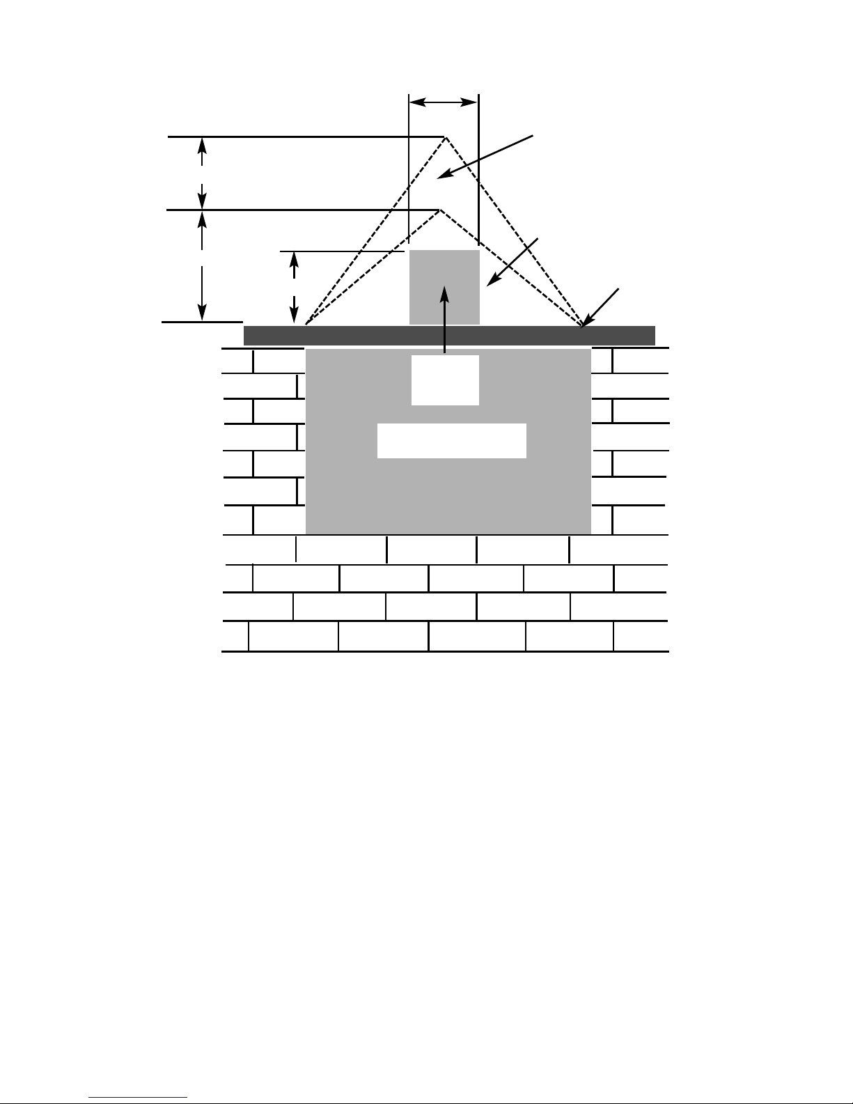
Fig. 7
10
400mm interactive area
6
00mm load triangle
T
he Interactive Zone -
O
penings, beams or joists within
this area need to be assessed.
L
oad triangle - No beam or
opening permissible within this
area
Lintel
e.g. 750mm x 75mm
Proposed Opening in
Chimney Breast
Minimum 200mm
Flue Pipe
Installation
Access
1
50mm
 Loading...