

Page 1
models
CLIP/LIM
P ROFESSIONAL POWER AMPLIFIER
LEVEL A
Handcrafted in Italy
Model
LEVEL B
POWER
1
0
SIGNAL
PROT/TEMP
ACTIVE
SIGNAL
CLIP/LIM
CLIP/LIM
P ROFESSIONAL POWER AMPLIFIER
LEVEL A
Handcrafted in Italy
Model
LEVEL B
POWER
1
0
SIGNAL
PROT/TEMP
ACTIVE
SIGNAL
CLIP/LIM
CLIP/LIM
P ROFESSIONAL POWER AMPLIFIER
LEVEL A
Handcrafted in Italy
Model
LEVEL B
POWER
1
0
SIGNAL
PROT/TEMP
ACTIVE
SIGNAL
CLIP/LIM
CLIP/LIM
P ROFESSIONAL POWER AMPLIFIER
LEVEL A
Handcrafted in Italy
Model
LEVEL B
POWER
1
0
SIGNAL
PROT/TEMP
ACTIVE
SIGNAL
CLIP/LIM
CLIP/LIM
P ROFESSIONAL POWER AMPLIFIER
LEVEL A
Handcrafted in Italy
Model
LEVEL B
POWER
1
0
SIGNAL
PROT/TEMP
ACTIVE
SIGNAL
CLIP/LIM
CLIP/LIM
LEVEL C LEVEL D
SIGNAL
PROT/TEMP
ACTIVE
SIGNAL
CLIP/LIM
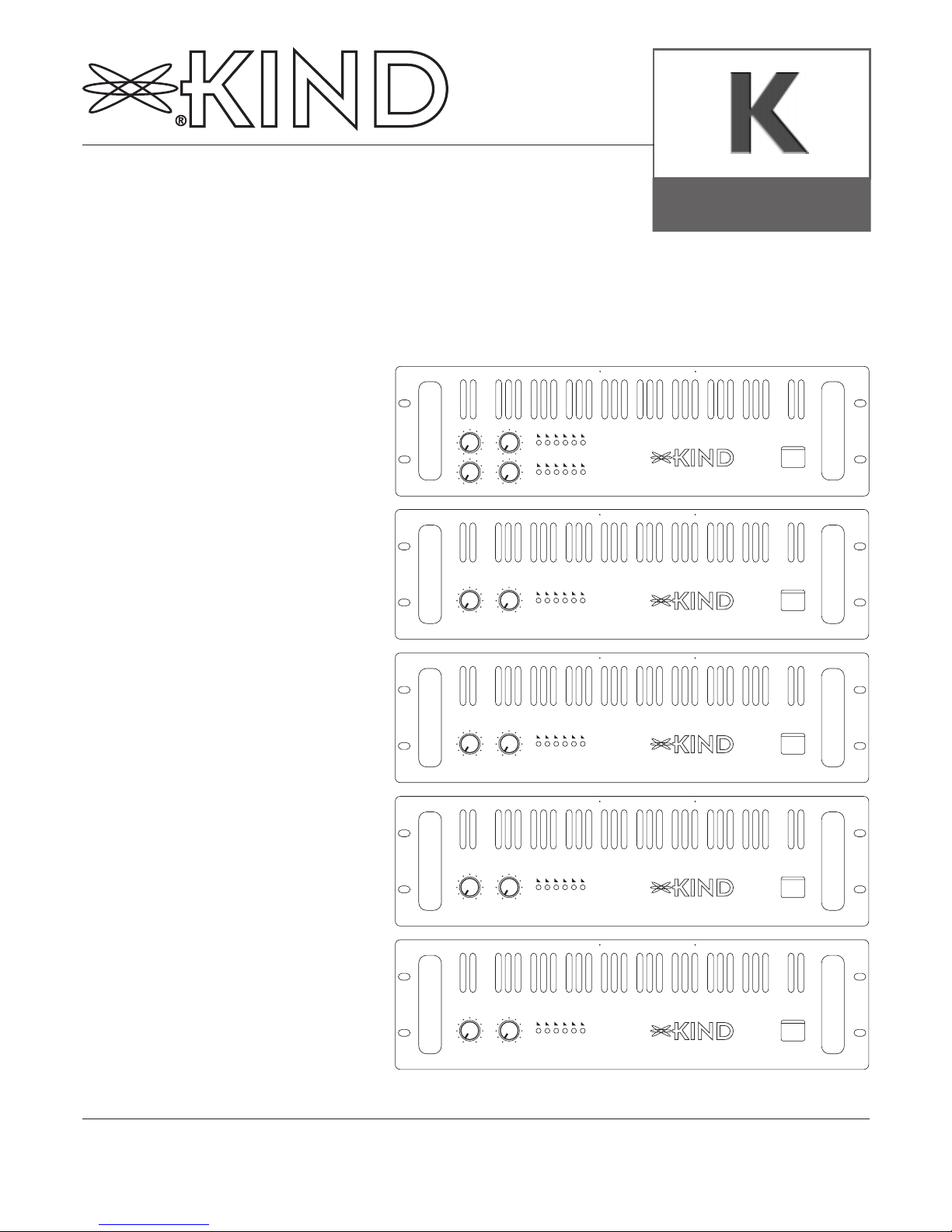
KQ
K5
K9
K12
K18
P ROFESSIONAL POWER AMPLIFIER
USER MANUAL
Page 2

Page 2KIND K models Power Amplifiers
Important Precautions
This symbol is used
to alert the operator to follow important operating procedures and precautions detailed in
documentation.
This symbol is used
to warn operators
that uninsulated
"dangerous voltages" are present
within the equipment enclosure that
may pose a risk of
electric shock.
1. Save the carton and
packing material
even if the equipment has arrived in
good condition.
Should you ever need to
ship the unit, use only
the original factory
packing.
2. Read all documenta-
tion before operating
your equipment.
Retain all documentation for future reference.
3. Follow all instructions
printed on unit chassis for proper operation.
4. Do not spill water or
other liquids into or
on the unit, or operate the unit while
standing in liquid.
5. Make sure power
outlets conform to
the power requirements listed on the
back of the unit.
6. Do not use the unit if
the electrical power
cord is frayed or
broken. The power
supply cords should be
routed so that they are
not likely to be walked
on or pinched by items
placed upon or against
them, paying particular
attention to cords and
plugs, convenience
receptacles, and the
point where they exit
from the appliance.
7. Always operate the
unit with the AC
ground wire connected to the electrical
system ground.
Precautions should be
taken so that the means
of grounding of a piece
of equipment is not
defeated.
8. Mains voltage must
be correct and the
same as that printed
on the rear of the
unit. Damage caused by
connection to improper
AC voltage is not covered by any warranty.
9. Have gain controls on
amplifiers turned
down during powerup to prevent speaker
damage if there are high
signal levels at the
inputs.
10. Power down &
disconnect units
from mains voltage
before making connections.
11. Do not use the unit
near stoves, heat
registers, radiators,
or other heat producing devices.
12. Do not block fan
intake or exhaust
ports. Do not operate
equipment on a surface
or in an environment
which may impede the
normal flow or air
around the unit, such as
a bed, rug, weathersheet,
carpet, or completely
enclosed rack. If the unit
is used in an extremely
dusty or smoky environment, the unit should be
periodically "blown free"
of foreign matter.
13. Do not remove the
cover. Removing the
cover will expose you to
potentially dangerous
voltages. There are no
user serviceable parts
inside.
14. Connecting ampli-
fier outputs to oscilliscopes or other test
equipment while the
amplifier is in bridged mode may damage
both the amplifier and
test equipment.
15. Do not drive the inputs
with a signal level greater than that required to
drive equipment to full
output.
16. Do not connect the
inputs/outputs of
amplifiers or consoles to any other voltage source, such as a
battery, mains source, or
power supply, regardless
of whether the amplifier
or console is turned on
or off.
17. Do not run the out-
put of any amplifier
channel back into
another channel's
input. Do not parallel-or series-connect
an amplifier output
with any other amplifier output. KIND is
not responsible for
damage to loudspeakers
for any reason.
18. Do not ground any
red ("hot") terminal.
For connection of "hot"
terminals to get parallel
high current mode see
appropriate paragraph.
19. Non-use periods. The
power cord of equipment should be unplugged from the outlet
when left unusued for a
long period of time.
20. Service information.
Equipment should be
services by qualified service personnel when:
A. The power supply cord
or the plug has been
damaged;
B. Objects have fallen, or
liquid has been spilled
into the equipment;
C. The equipment has
been exposed to rain;
D. The equipment protect
LED's remain continuously illuminates;
E. The equipment does not
appear to operate normally, or exhibits a
marked change in
performance;
F. The equipment has been
dropped, or the enclosure damaged.
21. To obtain service,
contact your nearest
KIND Service Center,
Distributor, Dealer, or
KIND Audio (Italy).
Page 3

Page 3 KIND K models Power Amplifiers
models
Table of Contents
Declaration of Conformity 4
Warranty Information 4
Introduction 5
Unpackaging 5
Installation / Mounting 5
Front - Back Panel / Side View 6
Operation 9
Mode Selection 10
Protection Features 14
Service Information 14
Wire Gauge Charts 15
Technical Specifications 16
Indice
Dichiarazione di Conformità 4
Informazioni per la Garanzia 4
Introduzione 5
Disimballaggio 5
Installazione / Montaggio 5
Vista Fronte - Retro - fianco 6
Utilizzo 9
Selezione del Modo d’uso 10
Caratteristiche delle Protezioni 14
Informazioni sulla Manutenzione 14
Tabella Cavi di Collegamento 15
Specifiche Tecniche 16
Page 4

Page 4KIND K models Power Amplifiers
models
Declaration of
Conformity
We declare as our sole responsibility that this product is in compliance with the EMC Directive
89/336/EEC and conforms to the
requirements of the Harmonized
Product Standards EN 55013
(Product Emissions), and EN
55020 (Product Immunity).
Dichiarazione di
Conformità
Dichiariamo sotto la nostra propria responsabilità che questo
prodotto é conforme con la
Direttiva Europea 89/336/EEC, e
conforme anche alle norme degli
standard d’armonizzazione
EN55013 (emissioni del prodotto), EN55020 (immunità del prodotto).
Déclaration de
Conformité
Nous déclarons sous notre seule
et unique responsabilité que ce
produit est conforme à la directive Européenne 89/336/EEC, et
qu’il répond également aux normes des standards d’harmonisation EN 55013 (Emission des
produits), ainsi qu’à la norme EN
55020 (Immunité des produits).
Konformitätserklärung
Wir erklären in alleiniger
Verantwortung, daß dieses
Produkt der EMV Verordnung
89/336/EEC entspricht und die
Erfordernisse der Einheitlichen
Produktnorm EN 55013
(Störstrahlung), sowie EN 55020
(Strahlungssicherheit) erfüllt.
INFORMAZIONI PER LA
GARANZIA
(Solo per l’Italia; Consultate
il vostro Rivenditore o
Distributore)
Esonero
KIND audio, non è responsabile
per danni causati dalla negligenza
oppure dall’ errata installazione o
dall’uso improprio di questo
amplificatore modello K verso
altoparlanti, amplificatori o altro
materiale.
Garanzia del prodotto
KIND audio garantisce i modelli
K per un periodo di tre anni
(1095 giorni) da difetti dei materiali e/o costruzione, sostituirà le
parti difettose e riparerà i prodotti malfunzionanti durante
questo periodo, solo quando il
difetto avviene con un uso e una
installazione normale.
L’unità deve essere ritornata alla
nostra fabbrica in porto franco
con allegata fattura o scontrino
fiscale che ne provi l’acquisto.
Questa garanzia prevede un
esame del prodotto ritornato,
per la verifica di eventuali difetti
di costruzione, il giudizio su questa materia rimane nostro e
insindacabile.
Questa garanzia non si estende a
prodotti che sono stati soggetti
ad un uso sbagliato, negligenza,
incidente, impropria installazione,
oppure dove i dati o i codici
sono stati rimossi o cancellati.
INFORMATIONS DE
GARANTIE
(ITALIE seulement; consultez votre marchand ou
distributeur)
GARANTIE-NACHRICHT
(nur beim ITALIEN; Ihrem
Fachhändler konsultieren)
WARRANTY
INFORMATION
(ITALY only; see your dealer
or distributor)
Disclaimer
KIND Audio, is not liable for any
damage to speakers, amplifiers,
or any other equipment that is
caused by negligence or improper installation and/or use of the
K model amplifier.
Product Warranty
KIND Audio guarantees the K
models to be free from defective
material and/or workmanship for
a period of three years (1095
days) from the date of sale, and
will replace defective parts and
repair malfunctioning products
under this warranty when the
defect occurs under normal
installation and use--provided the
unit is returned to our factory
via prepaid transportation with a
copy of the proof of purchase,
i.e., sales receipt. This warranty
provides that examination of the
returned products must indicate,
in our judgment, a manufacturing
defect. This warranty does not
extend to any product which has
been subjected to misuse,
neglect, accident, improper installation, or where the date code
has been removed or defaced.
Page 5

Page 5 KIND K models Power Amplifiers
models
Introduction
Congratulations on your purchase of a KIND audio power amplifier.
We would like to thank you for
your confidence in us and our
products.
The power amplifier was handmade in Italy. All the components
were selected. Although the
amplifier was designed to allow
straightforward and uninterrupted operation, improper handling
or incorrect installation could
damage the power amplifier.Your
amplifier represent the latest
technology in power amplifier
and design. Please read this
manual carefully as it contains
information vital to the safe operation of your amplifier.
Unpacking
Check the carton box and its
contents immediately to see if
there are any sign of damage.
Upon unpacking inspect the
amplifier, if you detect any damage inform the forwarding agent
without delay and ask for the
damage to be documentate.
Claims can only be made against
the forwarder agent by the consignee. Be sure to save the carton and all packaging materials
for the carrier's inspection.
It's good idea to save the carton
and packing material even if the
amplifier has arrived in good
condition. Should you ever need
to ship the unit back to KIND, or
one of its Service Center.
Using only the original factory
packaging will be the best way to
save the unit from carrier negligence.
Installation/Mounting
All K models amplifiers are 3rack space units that can mount
in a standard 19" rack. Four front
panel mounting holes are provided. Rear mounting ears give
additional support especially
important in mobile sound
systems.
The unit should not to be installed
in a location with:
•Too high ambient temperatures,
dust build-up or excessive humidity;
•Fog machines output’s oriented
to the fan’s input area of the
amplifier;
•Exhaust air ventilators and similar units near the fan's input area
at the rear of the amplifier;
•With permanent vibrations;
•With excessive induction or
magnetic fields due to tranformers and transmitters;
Introduzione
Congratulazioni per il vostro
acquisto di un'amplificatore di
potenza audio KIND. Noi vogliamo ringraziarvi per la fiducia che
date a noi e ai nostri prodotti. Il
vostro amplificatore é stato
costruito a mano in Italia. Tutti i
componenti sono stati selezionati. Sebbene l'amplificatore é stato
progettato per permettere il funzionamento continuo, l'uso
improprio o un'installazione
scorretta potrebbero danneggiarlo. Il vostro amplificatore rappresenta la tecnologia più avanzata
nel progetto di un'amplificatore
di potenza. Vi preghiamo leggere
questo manuale attentamente
siccome contiene informazioni
vitali per un utilizzo sicuro del
vostro amplificatore.
Disimballaggio
Controllate l'imballo in cartone e
il suo contenuto immediatamente per vedere se ci sono segni di
danneggiamento. Dopo il disimballaggio ispezionate l'amplificatore, se verificate qualche danno
informate lo spedizioniere senza
ritardo e chiedete che il danno
venga documentato. I reclami allo
spedizioniere possono essere
fatti solamente dal destinatario.
Assicuratevi di conservare l'imballo completo per l'ispezione
dello spedizioniere. E' buona idea
conservare l'imballo completo
anche se l'amplificatore arriva in
condizioni ottimali, potreste
averne bisogno per rispedirlo a
KIND o a uno dei suoi Centri
Assistenza. Usate solamente l'imballo originale, sraà il miglior
modo per salvaguardare l'apparecchiatura dalla noncuranza
degli spedizionieri.
Installazione/Montaggio
Tutti i modelli di amplificatori K
sono 3 unità, possono essere
montati in un rack 19" standard,
sono previsti 4 fori sul pannello
frontale per il montaggio. Per
avere un fissaggio ottimale,
importante nei sistemi mobili,
supporti addizionali sono presenti sul retro.
L’unità non dovrebbe essere installata in posti con:
•Temperatura in ambiente troppo alta, troppa polvere o eccessiva umidità;
•L’uscita di macchine del fumo
orientata nell’area d’ingresso
della ventola sul retro dell’amplificatore;
•Ventilatori di scarico e simili
unità vicino all’area d’ingresso
della ventola sul retro dell’amplificatore;
•Con vibrazioni permanenti;
•Con eccessiva induzione dovuta
al campo magnetico di trasformatori e trasmettitori;
Page 6

Page 6KIND K models Power Amplifiers
models
CLIP/LIM
P ROFESSIONAL POWER AMPLIFIER
LEVEL A
Handcrafted in Italy
Model
LEVEL B
POWER
1
0
SIGNAL
PROT/TEMP
ACTIVE
SIGNAL
CLIP/LIM
K18
3
4
5
1
2
133mm
57mm
483mm
6
7
98
OUTPUT 1
CHANNEL A
PIN 1 + Pos
PIN 1 - Gnd
CHANNEL B
PIN 2 + Pos
PIN 2 - Gnd
BRIDGE OUTPUT
PIN 1 + Pos
PIN 1 - Gnd
AC 230V
AC 115V
T 4A
T 5A
T 8A
AC SUPPLY
CAUTION:
replace fuse only
with correct type
and rating
W
T 6.3A
OUTPUT 2
CHANNEL B
PIN 1 + Pos
PIN 1 - Gnd
CHANNEL A
PIN 2 + Pos
PIN 2 - Gnd
T A
WARNING:
To reduce the risk of fire or electric
shock do not expose equipment to
rain or moisture, do not remove cover,
no use serviceable parts inside, refer
servicing to qualified service personnel.
See operating manual before using.
A
B
STEREO
BRIDGE
INPUTS
28066 Galliate (NO) Italy
MADE IN ITALY - EC
LIMITER
INPUT CONN:
XLR Pin 2 +
TRS Tip +
BRIDGE MODE:
use A input
S.N.
OUT
IN
KIND Audio
Galliate (NO), Italy
Made in E.U.
Model:K18
Output PWR per CH/Imp: 800/4
230VAC 50/60Hz 8A SERIAL
133mm
440mm
453mm
44mm
12
14
1516
13
11
10
Front Panel
Rear Panel
Side View
57mm
8
Page 7

Page 7 KIND K models Power Amplifiers
models
1. Rack mounting ears
Two front panel mounting holes
are provided on each mounting
ear.
2. Standard rack handles
Comfortable handles are provided for easy transport and
mounting operation.
3. Input attenuators
Two front panel precision 41 pc
input attenuators adjust level for
their respective amplifier channels. Minimum attenuation (-0dB)
equals maximum output. In the
bridged mode both attenuators
are used to control signal level; in
addition both must be set at the
same setting.
4. Clip/Limiter
Each channel has a LED that
lights at the real clipping points
indipendent from the load or
possible main voltage fluctuation,
and indicates (when switched on)
the limiter engaged.
5. Signal
Each channel has a LED that
lights when the output signal
(before output relay) is greater
than +10dBV.
6. Protect/Temp
Each amplifier has one red protect LED.When one of the channels is in protect mode for DC in
the output or high temperature,
LED will light. Internal protection
is fully separated for the channels, may occur that protect LED
lights up for one channel problem but the other channel may
work normally.
7.Active
The green active LED illuminates
to indicate that the amplifier is
turned on.
8. Fan exhaust ports
Heated air exits the amplifier
through the exhaust ports, located on the front and sides of the
amplifier chassis. Be sure not to
block this ports, especially when
rack-mounting the amplifier.
9.AC power switch
Use this to switch on the amplifier. An advanced soft-start limits
the toroidal transformer surges.
1. Supporti di montaggio
Due fori per il montaggio, ogni
lato, sono previsti sul pannello
frontale.
2. Maniglie standard
Comode maniglie sono fornite
per facilitare operazioni di trasporto e montaggio.
3.Attenuatori di ingresso
Due attenuatori di precisione a
41 pc sono presenti sul pannello
frontale per la taratura rispettiva
di ogni canale dell'amplificatore.
Minima attenuazione (-0dB)
uguale a massima uscita. Nell'uso
a ponte ambedue gli attenuatori
sono usati per controllare il livello di segnale; inoltre ambedue
devono essere posizionati nella
stessa posizione.
4. Clip/Limiter
Ogni canale ha un LED che lampeggia al punto di clip reale indipendentemente dal carico o da
una possibile variazione dell'alimentazione, indica anche (quando inserito) l'intervento del limiter.
5. Signal
Ogni canale ha un LED che lampeggia quando il segnale d'uscita
(prima del relé) é maggiore di
+10dBV.
6. Protect/Temp
Ogni amplificatore ha un LED
rosso di protezione. Quando uno
dei canali é in protezione per DC
in uscita oppure alta temperatura
il LED si illumina. Le protezioni
interne sono completamente
separate per i canali, potrebbe
succedere che il LED di protezione sia illuminato per problemi ad
un canale ma che l'altro canale
lavori normalmente.
7.Active
Il LED verde active si illumina per
indicare che l'amplificatore é
acceso.
8.Aperture di scarico
L'aria per il raffreddamento dell'amplificatore viene scaricata sul
fronte e sui fianchi dell'amplificatore attraverso le aperture di
scarico, accertatevi di non ostruire queste aperture specialmente
quando montate a rack l'amplificatore.
9. Pulsante di accensione
Usatelo per accendere l'amplificatore. Un sistema di soft-start
limita l'assorbimento del trasformatore toroidale.
Page 8

Page 8KIND K models Power Amplifiers
models
10. Speakon output connectors
For connection with speakontype speaker cables.The amplifier
outputs are three: output one
and two permit (each) connection of both channels (bi-wiring
mode) for stereo operation or
parallel, the bridge output permit
connection when using the
amplifier bridged or may plugged
with wired speakon when using
parallel high current mode. For
reference see drawings 1-4.
11. Fan intake grill
A 180 cubic meters of air per
hour fan's capacity has been
mounted behind the fan intake
grill draw cooling air into the
amplifier. The infinitely variable
speed control ensure low noise
operation and adapt the quantity
of air required from the actual
temperature inside the unit.
Thanks to this advanced system
low noise is guarantee and reduce dust introduced in the unit.
Do not block this intake!
12. Limiter switch
Push this to switch on the standard limiter, when amplifier may
be overdrived.
13. Mode selector switch
Push this switch to change operation mode from stereo to bridged mono. (See Mode Selection
paragraph)
14. Input connectors
XLR male and female are provided on each channel for balanced
or unbalanced input. For wiring
see drawings 1-4.
15. Moveable input board
Move the board when desire to
plug optional KIND I.O.C. cards
(as CROSSOVER-GAIN-EQ,
COMPRESSOR LIMITER etc.) to
expand amplifier performance.
Available from your authorized
KIND dealer.
16. A.C. Power cable
The K models have one A.C.
power cable. Before connection,
be sure that the cable is not
frayed or broken.The connection
must be made only in a plug with
the electrical ground wire
system.
10. Connettori di uscita
speakon
Da usarsi con connettori di tipo
speakon. Le uscite dell'amplificatore sono tre: le uscite uno e due
permettono (ognuna) la connessione di ambedue i canali (uso biwiring) per l'uso in stereo oppure in parallelo, l'uscita bridge permette la connessione quando
l'amplificatore è usato a ponte
oppure per inserire uno speakon
cablato, quando si usa l'amplificatore in parallelo ad alta corrente.
Per riferimento vedi disegni 1-4.
11. Griglia di aspirazione
del ventilatore
Una ventola da 180 metri cubi
per ora é montata dietro alla griglia e introduce l'aria per il raffreddamento nell'amplificatore. Il
controllo a velocità variabile assicura un basso rumore operativo
e adatta la quantità di aria richiesta in base alla temperatura reale
all'interno dell'unità. Grazie a
questo sistema avanzato é garantito un basso rumore e ridotta
la polvere introdotta nell'unità.
Non ostruite questa apertura!
12. Limiter switch
Premete questo switch per inserire lo standard limiter, quando
l'amplificatore è sovrapilotato.
13. Selettore d'uso
Premete questo switch per cambiare l'uso da stereo a pontato in
mono (vedi il paragrafo Selezione
d'uso).
14. Connettori di ingresso
Maschio e femmina XLR sono
forniti per ogni canale per l’ingresso bilanciato o sbilanciato.
Per il cablaggio vedi disegni 1-4.
15. Scheda di ingresso
removibile
Rimuovere questa scheda quando desiderate inserire le optional
KIND I.O.C. Cards (come
CROSSOVER-GAIN-EQ, COMPRESSOR LIMITER ecc.) per
espandere le prestazioni dell'amplificatore.
Disponibili presso il vostro rivenditore autorizzato KIND.
16. Cavo di alimentazione A.C.
I modelli K hanno un cavo di alimentazione A.C.. Prima di connetterlo, controllare che non sia
spelato o rotto. La connessione
va fatta solo in una presa che
abbia il sistema di messa a terra.
Page 9

Page 9 KIND K models Power Amplifiers
models
Operation
Connecting Power and
Circuit size requirements
Amplifier’s power requirement
are rated at 40% Duty Cycle
("severe" music condition). The
maximum power current draw
rating is limited only by the internal fuses. Consult the specification at the end of this manual for
the power to each amplifier will
demand. Mains voltage must also
be correct and the same as that
printed on the rear of the amplifier. Damage caused by connecting the amplifier to improper
AC voltage is not covered by any
warranty. Note: always switch off
and disconnect the amplifier
from mains voltage before
making audio connections, and as
an extra precautions, have the
attenuators turned down during
power-up.
Cooling Requirements
Amplifier use a forced air cooling
system to maintain a low, even
operating temperature.
Drawn by a infinitely variable
speed fan mounted behind the
rear panel, air enters through the
rear grill and courses through
the cooling fins of the heatsink,
which dissipates power transistor heat, before exiting through
the front panel and side ports.
Make sure that there is enough
space around the rear of the
amplifier to allow air to enter,
and around the units to allow the
heated air to exit. If the amp is
rack-mounted, do not use doors
or covers on the back of the
rack; the exhaust air must flow
without resistance. Note: whatever type of rack you are using,
make sure that the heated air
can escape freely, and that there
is not resistance to the intake of
cool air through the back grill.
Utilizzo
Connessione alla rete e
assorbimento
L’assorbimento dell’amplificatore
è stimato con 40% Duty Cycle
("severa" condizione musicale).
L'assorbimento massimo di corrente é limitato solamente tramite i fusibili interni. Consultate le
specifiche alla fine di questo
manuale per la potenza che
occorrerà all'amplificatore. Il voltaggio deve corrispondere a
quello stampato sul retro dell'amplificatore. Danni causati da
una connessione a un voltaggio
improprio non sono coperti da
nessuna garanzia. Note: spegnete
sempre e disconnettete l'amplificatore dall'alimentazione prima
di fare connessioni audio, e come
extra precauzione tenete gli attenuatori al minimo durante l'accensione.
Esigenze di raffreddamento
L'amplificatore usa un sistema ad
aria forzata per mantenere bassa
la temperatura operativa.
Una ventola a velocità variabile
montata all'interno del pannello
retro introduce l'aria nell'unità
tramite la griglia. L'aria passa
attraverso le alette di raffreddamento del dissipatore, dissipando
il calore generato dai transistor,
prima di essere scaricata attraverso le aperture sul fronte e sul
fianco. Fate in modo di lasciare
sufficiente spazio sul retro dell'amplificatore per permettere
all'aria di entrare e intorno all'unità per permettere all'aria calda
di uscire. Se l'amplificatore é
montato a rack, non usate porte
o coperchi sul retro del rack; l'aria di scarico deve fluire senza
resistenza. Note: qualunque tipo
di rack stiate usando, accertatevi
che l'aria calda possa uscire liberamente e che non ci sia resistenza all'ingresso di aria fredda
attraverso la griglia sul retro.
Page 10

Page 10KIND K models Power Amplifiers
models
Selezione del modo d’uso
Il pulsante per la selezione d'uso
(situato sul pannello retro tra le
connessioni di ingresso per il
canale A e B) configura l'amplificatore per entrambi gli usi stereo oppure pontato in mono.
L'amplificatore è settato in fabbrica per l'uso in stereo. Per pontare l'amplificatore, spegnerlo,
premere il pulsante nella posizione "bridge". Il segnale va connesso solo al canale A. Ambedue gli
attenuatori sono usati per controllare il livello di segnale; inoltre, ambedue devono essere
posizionati nella stessa posizione.
Uso in stereo
Nell'uso in stereo ambedue i
canali operano indipendentemente, con i propri attenuatori di
ingresso controllano i propri
rispettivi livelli. Segnale all'ingresso del canale A produce l'uscita
del canale A, lo stesso per il canale B. Il carico minimo raccomandato per l'uso in stereo é 2
Ohms per canale. Entrambi i connettori di ingresso maschio e
femmina XLR possono essere
usati. Gli altoparlanti sono collegati al connettore di uscita
speakon uno per i canali A e B, e
raddoppiati al connettore di uscita speakon due per l'aggiunta di
più altoparlanti. Note: non connettere altoparlanti all'uscita
bridge (centrale) quando usate
l'amplificatore in stereo (vedi
disegno 1).
Uso a ponte (uscita ad
alto voltaggio)
L'uso pontato in mono lega
ambedue i canali dell'amplificatore assieme per fare un amplificatore mono a singolo canale
molto potente. Il segnale va connesso solo al canale A. Ambedue
gli attenuatori sono usati per
controllare il livello di segnale;
inoltre, ambedue devono essere
posizionati nella stessa posizione.
Entrambi i connettori di ingresso
maschio e femmina XLR possono
essere usati. Gli altoparlanti sono
connessi solo al connettore centrale bridge (vedi disegno 2).
Uso in parallelo
Per mandare lo stesso segnale ad
ambedue i canali connettere il
segnale di ingresso al canale A
tramite il connettore XLR femmina e fare un ponte tra il connettore maschio del canale A e il
connettore femmina del canale B.
Ambedue i canali usano lo stesso
segnale di ingresso, ambedue
opereranno indipendentemente.
Gli altoparlanti sono connessi
come nell'uso in stereo (vedi
disegno 3).
Mode Selection
The push-button mode select
switch (located on the rear panel
between input connection for
channels A and B) configures the
amplifier for either stereo mode
or bridged mono mode.
Amplifiers are factory setted for
stereo mode. To bridge the
amplifier, turn heat off, and push
the mode selection switch to the
"bridge position". Signal is applied
to channel A's input only. Both
attenuators are used to control
signal level; in addition, both must
be set at the same setting.
Stereo Mode
In stereo mode, both channels
operate independently, with their
input attenuators controlling
their respective levels. Signal at
channel A's input produces output at channel A's output, while
signal at the channel B's input
produces output at the channel
B's output. Recommended minimum nominal load impedance for
stereo operation is 2 Ohms per
channel. Either the XLR male or
female input connectors may be
used. Loudspeakers are connected to the speakon output connectors one for channels A and
B, and replicate to the speakon
output connectors two for
adding more speakers. Note: do
not connect speakers to the
bridge output (central) when
using the amplifier in stereo
mode. (See drawing 1).
Bridged Mono Mode (high
voltage output)
Bridged mono mode straps both
amplifier channels together to
make a very powerful single
channel monaural amplifier. Signal
is applied to channel A's input
only. In the bridged mode both
attenuators are used to control
signal level; in addition, both must
be set at the same setting. Either
the XLR male or female input
connectors may be used.
Loudspeaker are connected only
to the central bridge connector
(See drawing 2).
Parallel Mode
To send the same signal to both
channels, connect the input signal
to channel A via the XLR female
input connector and make a
wiring between channel A male
connector and channel B female
connector. Both channels share
the input signal, both will operate
independently. Speaker are connected as in stereo mode (See
drawing 3).
Page 11

Page 11 KIND K models Power Amplifiers
models
Parallel Mono Mode
This feature will permit to double the power in halve impedence. To send the same signal to
both channels, connect the input
signal to channel A via the XLR
female input connector and make
a wiring between channel A male
connector and channel B female
connector. Both channels share
the input signal. In the parallel
(high current output) mode both
attenuators must be set at the
maximum position (is not possible adjust the level from the
amplifier in this mode). Plug a
speakon connectors wiring pole
1+/1- on central bridge output.
Speakers are connected as in stereo mode (see drawing 4).
Outputs Wiring
Suggestions
Use flexible double isolated cable
and be sure that the resistance of
the lead is kept low. This helps
prevent power loss and increases
the impulse response of the
sound reproduction. With the
KIND amplifier loudspeaker is
controlled exactly in accordance
with signal waveform, and accelleration or breaking of the loudspeaker membrane is performed
with precision. This prevents
uncontrolled overshooting which
is particularly audible in the low
frequency range. The resistence
of the loudspeaker cable can be
affected by the lenght and section of the cable. Speakon cable
connectors permit to use cable
of 6 mm max.
The recommended cable section
depend on the power of the connected loudspeaker and the lenght of the lead.(For reference see
table "Wire Gauge Charts").
Uso in parallelo mono
Questa funzione vi permetterà di
raddoppiare la potenza su un’impedenza dimezzata. Per mandare
lo stesso segnale ad ambedue i
canali connettere il segnale di
ingresso al canale A tramite il
connettore XLR femmina e fare
un ponte tra il connettore
maschio del canale A e il connettore femmina del canale B.
Ambedue i canali usano lo stesso
segnale di ingresso. Nell'uso in
parallelo ad alta corrente ambedue gli attenuatori devono essere
posizionati al massimo (non é
possibile la regolazione del livello
dall'amplificatore in questo
modo). Connettete un connettore speakon nell'uscita centrale
bridge collegando tra loro i poli
1+/1-. Gli altoparlanti sono collegati come nell'uso in stereo (vedi
disegno 4).
Suggerimenti per i
cablaggi delle uscite
Usate cavi flessibili con doppio
isolamento e assicuratevi che la
resistenza dei conduttori sia
tenuta bassa. Questo preverrà
perdite di potenza e accrescerà
la risposta agli impulsi della riproduzione del suono. Con gli amplificatori KIND gli altoparlanti
sono controllati esattamente in
accordo con la forma d'onda di
segnale, e accellerazioni o arresto della membrana dell'altoparlante sono effettuati con precisione. Questo previene movimenti incontrollati ed esagerati
della membrana dell'altoparlante
particolarmente udibili alle basse
frequenze. La resistenza dei cavi
dell'altoparlante può essere condizionata dalla lunghezza e dalla
sezione del cavo. I connettori
speakon permettono di usare
cavi fino a 6 mm. di sezione. La
sezione di cavo raccomandata
dipende dalla potenza dell'altoparlante e dalla lunghezza del
cavo. (Per riferimento vedi tabella
"Wire Gauge Charts").
Page 12

Page 12KIND K models Power Amplifiers
models
+
= Unbalanced
12
3
Male
-
WARNING:
To reduce the risk of fire or electric
shock do not expose equipment to
rain or moisture, do not remove cover,
no use serviceable parts inside, refer
servicing to qualified service personnel.
See operating manual before using.
A
B
STEREO
BRIDGE
INPUTS
28066 Galliate (NO) Italy
MADE IN ITALY - EC
LIMITER
INPUT CONN:
XLR Pin 2 +
TRS Tip +
BRIDGE MODE:
use A input
S.N.
OUT
IN
OUTPUT 1
CHANNEL A
PIN 1 + Pos
PIN 1 - Gnd
CHANNEL B
PIN 2 + Pos
PIN 2 - Gnd
BRIDGE OUTPUT
PIN 1 + Pos
PIN 1 - Gnd
AC 230V
AC 115V
T 4A
T 5A
T 8A
AC SUPPLY
CAUTION:
replace fuse only
with correct type
and rating
W
T 6.3A
OUTPUT 2
CHANNEL B
PIN 1 + Pos
PIN 1 - Gnd
CHANNEL A
PIN 2 + Pos
PIN 2 - Gnd
T A
+
= Unbalanced
12
3
Male
-
+
-
1
2
3
Female
OUTPUT 1
CHANNEL A
PIN 1 + Pos
PIN 1 - Gnd
CHANNEL B
PIN 2 + Pos
PIN 2 - Gnd
BRIDGE OUTPUT
PIN 1 + Pos
PIN 1 - Gnd
AC 230V
AC 115V
T 4A
T 5A
T 8A
AC SUPPLY
CAUTION:
replace fuse only
with correct type
and rating
W
T 6.3A
OUTPUT 2
CHANNEL B
PIN 1 + Pos
PIN 1 - Gnd
CHANNEL A
PIN 2 + Pos
PIN 2 - Gnd
T A
WARNING:
To reduce the risk of fire or electric
shock do not expose equipment to
rain or moisture, do not remove cover,
no use serviceable parts inside, refer
servicing to qualified service personnel.
See operating manual before using.
A
B
STEREO
BRIDGE
INPUTS
28066 Galliate (NO) Italy
MADE IN ITALY - EC
LIMITER
INPUT CONN:
XLR Pin 2 +
TRS Tip +
BRIDGE MODE:
use A input
S.N.
OUT
IN
1. Stereo Mode
2. Bridged Mono Mode
Input Wiring / Input - Output Mode Connections
Page 13

Page 13 KIND K models Power Amplifiers
models
WARNING:
To reduce the risk of fire or electric
shock do not expose equipment to
rain or moisture, do not remove cover,
no use serviceable parts inside, refer
servicing to qualified service personnel.
See operating manual before using.
A
B
STEREO
BRIDGE
INPUTS
28066 Galliate (NO) Italy
MADE IN ITALY - EC
LIMITER
INPUT CONN:
XLR Pin 2 +
TRS Tip +
BRIDGE MODE:
use A input
S.N.
OUT
IN
OUTPUT 1
CHANNEL A
PIN 1 + Pos
PIN 1 - Gnd
CHANNEL B
PIN 2 + Pos
PIN 2 - Gnd
BRIDGE OUTPUT
PIN 1 + Pos
PIN 1 - Gnd
AC 230V
AC 115V
T 4A
T 5A
T 8A
AC SUPPLY
CAUTION:
replace fuse only
with correct type
and rating
W
T 6.3A
OUTPUT 2
CHANNEL B
PIN 1 + Pos
PIN 1 - Gnd
CHANNEL A
PIN 2 + Pos
PIN 2 - Gnd
T A
1-
1+
2+
2-
WARNING:
To reduce the risk of fire or electric
shock do not expose equipment to
rain or moisture, do not remove cover,
no use serviceable parts inside, refer
servicing to qualified service personnel.
See operating manual before using.
A
B
STEREO
BRIDGE
INPUTS
28066 Galliate (NO) Italy
MADE IN ITALY - EC
LIMITER
INPUT CONN:
XLR Pin 2 +
TRS Tip +
BRIDGE MODE:
use A input
S.N.
OUT
IN
OUTPUT 1
CHANNEL A
PIN 1 + Pos
PIN 1 - Gnd
CHANNEL B
PIN 2 + Pos
PIN 2 - Gnd
BRIDGE OUTPUT
PIN 1 + Pos
PIN 1 - Gnd
AC 230V
AC 115V
T 4A
T 5A
T 8A
AC SUPPLY
CAUTION:
replace fuse only
with correct type
and rating
W
T 6.3A
OUTPUT 2
CHANNEL B
PIN 1 + Pos
PIN 1 - Gnd
CHANNEL A
PIN 2 + Pos
PIN 2 - Gnd
T A
OUTPUT 1
CHANNEL A
PIN 1 + Pos
PIN 1 - Gnd
CHANNEL B
PIN 2 + Pos
PIN 2 - Gnd
BRIDGE OUTPUT
CHANNEL A/B
PIN 1 + Pos
PIN 1 - Gnd
CHANNEL C/D
PIN 2 + Pos
PIN 2 - Gnd
OUTPUT 2
CHANNEL C
PIN 1 + Pos
PIN 1 - Gnd
CHANNEL D
PIN 2 + Pos
PIN 2 - Gnd
3. Parallel Input
4. Parallel Mono Mode
KQ
Output Mode
Input Wiring / Input - Output Mode Connections
IMPORTANT NOTE: In the parallel
mode both attenuators must be set at
the maximum position (is not possible
adjust the level from the amplifier in
this mode).
Page 14

Page 14KIND K models Power Amplifiers
models
Protection Features
Every model incorporates sophisticates protection features.
Derived from KIND years experience with installer and rental
Companies, the group of circuits
is the latest technology for
amplifiers and load protection.
Real Load Limiter
By pushing the switch on the
back side will activate the limiter
function. This is indicated by illumination of CLIP/LIM LED. The
channel gain will automatically be
reduced, protecting the loudspeakers against the damaging
high power or distorted signal.
When switched the limiter function is activated automatically as
soon as the amplifier is overdrived (up to 10dB) or there is
uncontrolled feedback, oscillation, or an improper equipment
setting or malfunction upstream
from the amplifier. Also if limiter
function is activated normal program transient will not trigger
the limiter; only steady or excessive clipping will. The limiter do
not affect the signal bandwidth.
Thermal Protection
If the heatsink temperature reaches an abnormally high temperature the amplifier will protect
itself by disconnecting loudspeakers and shutting down until
sufficiently cooled. Durign this
time the protect LEDs will light.
Short Circuit
If an output is shorted (i.e.,
defective speakers or wrong
speaker wires) the short protection and thermal circuitry will
automatically protect the amplifier. Same protection will limit
the output stage in case the load
connected will be lower than 1
Ohm. If the short circuit remains,
the load will be disconnected by
the thermal protection circuitry.
DC Voltage Protection
If an amplifier channel detect DC
voltage at its output terminals
the output relay will immediately
open to prevent loudspeaker
damage. The protect LED will
light.
Service Information
To obtain service, contact your
nearest KIND Service Center,
Distributor, Dealer or KIND
Audio (Italy).
Caratteristiche delle protezioni
Ogni modello incorpora delle
protezioni sofisticate. Sono derivate dall'esperienza di KIND con
installatori e service, l'insieme dei
circuiti é la più recente tecnologia per la protezione dell'amplificatore e del suo carico.
Limiter su carico reale
Premendo lo switch sul retro
sarà attivata la funzione limiter.
L’intervento è indicato dall'illuminazione del CLIP/LIM LED. Il guadagno del canale sarà automaticamente ridotto, proteggendo
l'altoparlante da danni dovuti
all'alta potenza o al segnale
distorto. La funzione limiter é
attivata automaticamente non
appena l'amplificatore é sovrapilotato (sopra i 10dB) oppure
quando c'é un feedback, oscillazioni, equipaggiamento malfunzionante o mal settato a monte dell'amplificatore. Anche se il limiter
é attivato nel normale programma i transienti non lo rendono
efficace. Il limiter non condiziona
l'ampiezza di banda.
Protezione termica
Se la temperatura del dissipatore
raggiunge una condizione anormale, l'amplificatore si proteggerà
da solo sconnettendo gli altoparlanti e riconnettendoli quando
sarà sufficientemente raffreddato.
Durante questo periodo il LED
di protezione si illuminerà.
Corto circuito
Se un'uscita é cortocircuitata
(per es. altoparlanti difettosi
oppure cablaggi degli altoparlanti
errati) la protezione sul corto, e
la protezione termica proteggeranno l'amplificatore. La stessa
protezione limiterà lo stadio di
uscita nel caso che il carico connesso sia minore di 1 Ohm. Se il
corto circuito persiste, il carico
sarà disconnesso dal circuito di
protezione termica.
Protezione DC
Se il canale di un amplificatore
individua una DC alla propria
uscita, il relé d'uscita aprirà
immediatamente per prevenire il
danneggiamento dell'altoparlante.
Il LED di protezione si illuminerà.
Informazioni sulla manutenzione
Per avere la manutenzione, contattate il vostro più vicino
Servizio Assistenza KIND,
Distributore, Rivenditore, oppure
KIND Audio (Italy).
Page 15

models
Page 15 KIND K models Power Amplifiers
Wire Gauge Charts
Stranded Cable Length.(Mt) Wire Section (mm2) % Power Loss (8 Ohms load) % Power Loss (4 Ohms load) % Power Loss (2 Ohm)
————————————————————————————————————————————————————
5 0.75 1.5 3 6
1.5 0.75 1.5 3
2.5 0.44 0.88 1.76
4 0.28 0.56 1.12
————————————————————————————————————————————————————
10 0.75 3 6 12
1.5 1.5 3 6
2.5 0.88 1.76 3.52
4 0.56 1.12 2.24
6 0.38 0.76 1.52
————————————————————————————————————————————————————
20 0.75 6 12 24
1.5 3 6 12
2.5 1.75 3.5 7
4 1.13 2.25 4.5
6 0.75 1.5 3
————————————————————————————————————————————————————
30 0.75 8.9 17.8 35.6
1.5 4.45 8.9 17.8
2.5 2.75 5.5 11
4 1.75 3.5 7
6 1.13 2.25 4.5
————————————————————————————————————————————————————
50 1.5 7.5 15 30
2.5 4.5 9 18
4 2.75 5.5 11
6 1.9 3.8 7.6
Page 16

Power output per channel RMS
1KHz (1% THD) both channels driven
Bridge MONO
Distortion (THD)
Frequency response
Input sensitivity (unbalanced)
Input impedance
Signal-to-Noise Ratio
Slew rate
Damping factor 8Ω 10Hz to 1KHz
Input connectors
Output connectors
General protection
Cooling
Mains supply
Power requirement 230V (40% Duty Cycle/2
Ω)
Dimension WxHxD / U rack 19"
Weight Kg.
483x133x453 / 3U (without handle)
115/230VAC ±10% 50 - 60Hz internally set by voltage links.
Electronic protection against output short, open circuit and load mismatch condition.
Thermal protection against heatsink over temperature (inadequate ventilation), automatic re-set.
Relays controlled delayed turn-on, load protection and prevents inrush current surges.
n 2 SPEAKON output with both channels wired (bi-wiring) and n 1 central SPEAKON for bridge mono output
Balanced: XLR 3-31 male and female (Pin 2 Hot) per channel.
Greather than -96dB ref. full output power, 20Hz to 20 KHz.
20 KΩ Balanced.
+4dB (1.2V) input for full output power into a 4Ω load.
10 Hz to 30 KHz +0, -1.0dB.
Indicators
Plug-in cards to mount on moveable input board:
LC1 card Limiter with adjustable compression
FC1 card Hi/Low pass filter 120Hz (variable by component satatus)/18dB oct, Horn EQ +-12dB, adjustable output +7/-10dB
AUX card usable by the customer to personalize the input signal as desire, creating a own circuitry
Options
25VµS
K5
K9 K12
K18
1200W
850W
700W
14net/17 packed
19net/22 packed
22net/25 packed
Single fan and single tunnel; fan on the rear with electronic variable speed (front exhausting)
>300
<0.05
300W / 8Ω
450W / 4Ω
550W / 2Ω
900W / 8Ω
1100W / 4Ω
<0.05
400W / 8Ω
600W / 4Ω
750W / 2Ω
1200W / 8Ω
1400W / 4Ω
<0.05
500W / 8Ω
800W / 4Ω
1000W / 2Ω
1600W / 8Ω
2000W / 4Ω
LED's for: Active, Prot/Temp, Signal, Clip/Limit
16net/19 packed
180W / 8Ω
250W / 4Ω
350W / 2Ω
500W / 8Ω
700W / 4Ω
450W
<0.05
KQ
1000W
22net/25 packed
<0.05
4x250W / 8Ω
4x400W / 4Ω
2x800W / 8Ω
Circuitry
Bipolar Class AB
Limiter
Real-Load Peak limiter, switchable, standard on all units
K models Specifications
KIND is a trademark of
AUDIO & AUDIO GROUP S.r.l.
Via Montello, 19 - I-28066 Galliate (NO) ITALY
Tel. +39 0321/865271 - Fax +39 0321/861674
e-mail: info@kindaudio.com
www.kindaudio.com
In line with development policy specifications may change without future notice.
We made our best to guarantee the information accuracy included on this publication, the AUDIO & AUDIO GROUP don’t undertake responsibility for mistakes or impresions.
V 1.2 © 2000 AUDIO & AUDIO GROUP S.r.l. All rights reserved. Printed in Italy 02/00.
 Loading...