


AIR/HYDRAULIC
BOTTLE JACK
TRUCK AIR
POWER
FILTERED/REGULATED
2X
FASTER
WITH AIR
K12131
20T CAPACITY
K12130
12T CAPACITY
LOCK BUTTON
AUTO
MANUAL &
AIR OPERATED
HEIGHT
ADJUSTABLE
SADDLE
K12130 - 12 Tonne
K12131 - 20 Tonne
ED1 (May 16)
2
AIR/HYDRAULIC BOTTLE JACK
50FAN
Table of Contents
Know your product..................................................................2
Air Hydraulic Bottle Jack Safety Instructions....................2-3
Air Hydraulic Bottle Jack Operation .......... ........................5-6
Warranty...................................................................................7
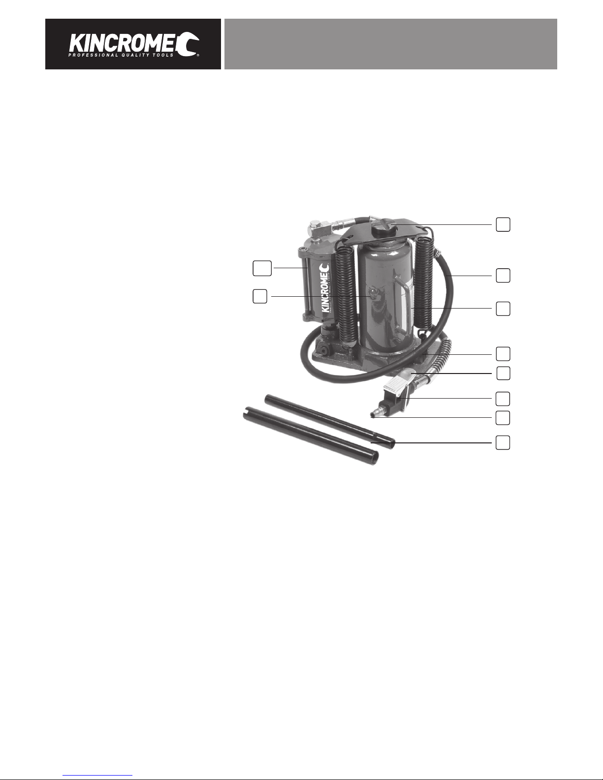
Know your product
1. Saddle (Adjustable Screw Type)
2. Air Inlet Hose
3. Carry Handle
4. Release Valve
5. Auto Lock Button
6. Air Valve Assembly
7. Air Inlet (Nitto Style Fitting)
8. Handles
9. Oil Filler Plug
10. Air Motor
11. Manual Pump Lever (not shown)
10
9
6
7
8
2
1
3
4
5
SPECIFICATION
Model No ...................................................... K12130 ............................................ K12131
Lifting Capacity ............................................ 12 Tonne .......................................... 20 Tonne
........................................................................ 12,000kg .......................................... 20,000kg
Maximum Height........................................... 495mm ............................................ 520mm
Minimum Height .......................................... 250mm ........................................... 260mm
Head Cap Diameter...................................... 40mm .............................................. 45mm
Ram Travel ...................................................165mm ............................................ 170mm
Head Cap Screw Height ............................... 80mm .............................................80mm
Operating Pressure ..................................... 110psi - 135psi ................................ 110psi - 135psi
Note: A minimum of 115psi is required to raise to the rated capacity load
Base Dimensions ......................................... 197mm x 118mm ............................ 223mm x 133mm
Hose Length ................................................. 1m.................................................... 1m
Air Fitting....................................Nitto Style 1/4” .................................................. Nitto Style 1/4”
Weight……………………… .............................. 12kg ................................................. 15kg

3
AIR/HYDRAULIC BOTTLE JACK
GENERAL SAFETY WARNINGS
Save all warnings and instructions for future reference.
WARNING! Read all safety warnings and all instructions. Failure to follow the warnings and instructions may result in
electric shock, fire and/or serious injury.
IMPORTANT SAFETY INFORMATION
The use of a vehicle jack has inherent dangers to avoid risk of personal injury or property damage make sure you are fully aware
of the operating instructions for this product, the recommendations in the vehicle owners manual for jacking of your vehicle prior
to lifting the vehicle. Do not exceed maximum lifting capacity of this jack. This jack is intended for automotive use only. Be aware
that large or heavy vehicles may exceed jack’s stated capacity check vehicle owners manual or contact the vehicle manufacturer. Do
not use for any other purpose except the raising and lower of vehicles, Never use to raise any structure or building, Do not lift any
human load and never ride on jack.
Preparing Work Area
Before using jack to lift vehicle, it is important to prepare work area properly. Follow this procedure each time the jack is used to
help prevent property damage and or serious injury.
1. Thoroughly inspect jack for damage or wear before each use. Briefly test operation of unloaded jack before using to lift any
load. If jack is damaged or is malfunctioning DO NOT LIFT ANY LOAD until the problem is corrected.
2. The Vehicle manufacturer’s owner’s manual should be consulted prior to the lifting of the vehicle. It will advise safety
precautions, jacking procedure, vehicle weight, recommended jack type, and location of jack support areas on vehicle.
NEVER EXCEED WORKING LOAD LIMIT OF JACK.
3. Clear children and others from work area before moving or lifting vehicle. Another adult should be nearby for extra safety
and assistance but must be clear of vehicle as it is moved or lifted. No person should remain in a vehicle that is being
jacked. No person should enter a vehicle which is supported by a jack or by vehicle support stands. No person should lean
into a vehicle which is supported by a jack or by vehicle support stands.
4. No person should place any portion of their body under a vehicle that is supported by a jack.
5. Clear obstructions from work area. Working in tight or cluttered work areas is dangerous.
6. The hydraulic vehicle jack should be used for lifting and lowering only; the raised vehicle should be supported on vehicle
support stands.
7. Be sure jack and vehicle are on solid, level ground such as paved or concrete driveway or garage floor. The jack should
be used on level firm ground wherever possible. Uneven or sloped surfaces create hazardous working conditions and
dangerously impeded the function of the jack.
8. With vehicle in proper position, set vehicle’s parking brake or emergency brake and put gear-shift in park (manual
transmissions should be placed in lowest gear). TURN VEHICLE IGNITION OFF AND TO THE “LOCK” POSITION making sure
steering wheel locks.
9. It is recommended that the wheels of the vehicle be chocked. Do not rely on vehicle transmission or brakes to hold vehicle
in position. Chock all wheels of vehicle not being lifted off the ground to prevent vehicle rolling. Using wedge-shaped blocks
that tire cannot roll over, position one chock tight against the tyre in both forward and reverse rolling paths.
10. The load should be centrally located on the head cap. Off centre loads can be unstable.
11. The hydraulic vehicle jack should be used for lifting and lowering only; the raised vehicle should be supported on vehicle
support stands. Vehicle support stands (not included) will be needed to support vehicle once it is in raised position. Have
jack stands, vehicle support stands capable of supporting vehicle weight ready nearby for use. Read and understand jack
stand manufacturer’s instructions and safety information before use and before lifting the vehicle with this jack.
12. Plan location of jack beneath vehicle, making sure jack will be contacting only a jack support area of vehicle. Consult
vehicle owner’s manual for location of jack support areas.

4
AIR/HYDRAULIC BOTTLE JACK
50FAN
Personal Safety
1. Stay alert. Watch what you are doing and use common sense when operating the tool. Do not use the tool while tired or
under the influence of drugs, alcohol, or medication. A moment of inattention while operating the tool increases the risk
of injury to persons.
2. Dress properly. Do not wear loose clothing or jewellery. Contain long hair. Keep hair, clothing, and gloves away from
moving parts. Loose clothes, jewellery, or long hair increases the risk of injury to persons as a result of being caught
in moving parts.
3. Avoid unintentional starting. Be sure the switch is off before connecting to the air supply. Do not carry the tool while
touching the switch or connect the tool to the air supply with the switch on.
4. Do not overreach. Keep proper footing and balance at all times. Proper footing and balance enables better control of the
tool in unexpected situations.
5. Use safety equipment. A dust mask, non-skid safety shoes and a hard hat must be used for the applicable conditions.
6. Always wear eye protection. Wear ANSI-approved safety goggles.
7. Always wear hearing protection when using the tool. Prolonged exposure to high intensity noise is able to
cause hearing loss.
Unpacking
Unpack all the components from the box.
When unpacking the Air/Hydraulic bottle jack carefully inspect for any damage that may have occurred during transit.
Check for loose parts, missing parts or damaged parts.
1. Ensure all packaging materials are disposed of as per your local council guide lines.
Bleeding / Venting Trapped Air
Note: Before first use, the hydraulic ram may need to be purged. Some air may intrude in the hydraulic system due to movement
during shipping. Air bubbles can become trapped inside the hydraulic system, thereby reducing the efficiency of the Jack.
Purge air from the system if efficiency drops.
1. Assemble the two handles (8) together, ensure that pins align with slots.
2. Place the slotted end of the handles (8) over the release valve (4) and turn 1-1/2 turns counter-clockwise.
Remove the oil filler plug (9) on the side of the jack reservoir.
3. Put the Handles (8) into the Manual Pump Lever (11) and rapidly pump the Handle (8) ten times to purge air from the hydrau-
lic system.
4. Use the Handle (8) to turn the Release Valve (4) clockwise until tight.
5. Top off Jack Reservoir with a high quality hydraulic jack oil and re-install the oil filler plug (9)
OPERATION
Before first using jack carry out the following preparation:
1. Check oil level - Open release valve (4) with handle (8) not more than two turns and press down on saddle (1) to ensure piston
is fully down, then remove oil filler plug (9). Oil should be level with bottom of filler hole. Adjust level as necessary and
replace oil filler plug (9)
2. Bleed system - refer to the above “Bleeding/Venting Trapped Air”.
3. Lubricate - Oil the pivots of the manual pump mechanism and the screw thread of the saddle (1) post. Put two or three drops
of air tool oil into the inlet of the air inlet (7). Connect to air supply and operate for three seconds to distribute lubricant.
4. Air supply - An in-line filter is recommended.

5
AIR/HYDRAULIC BOTTLE JACK
Raising the Ram Plunger (using the Pump Lever 11)
WARNING!: Do not overload this jack. Maximum capacity, refer to the specification section for the max working limits
1. Assemble the handle (8), ensure that pins align with slots.
2. Place vehicle in the park, with hand brake on and wheel securely chocked to prevent inadvertent vehicle movement.
3. Locate and close release valve (4) by turning Handle (8) clockwise until firm resistance is felt to further thread engagement.
4. Verify lift point, centre jack saddle under lift point.
Caution: The Vehicle manufacturer’s owner’s manual should be consulted for the correct lift points prior to the lifting of the vehicle.
5. Insert the assembled handle (8) into the manual pump lever (11) and slowly pump the handle (8) until the saddle (1) contact
the vehicle’s lift point. To lift, continue pumping until load reaches desired height.
6. Immediately secure lifted load with appropriately rated jack stands.
Raising the Ram Plunger (using the Control Valve (6)
Caution: Do not use an extender on the air hose (2) or the operating handle.
1. Place vehicle in the park, with hand brake on and wheel securely chocked to prevent inadvertent vehicle movement.
2. Connect the air hose from the compressor to the air inlet (7) of the Air/Hydraulic Jack.
3. Locate and close release valve (4) by turning Handle (8) clockwise until firm resistance is felt to further thread engagement.
4. Verify lift point, centre jack saddle under lift point.
Caution: The Vehicle manufacturer’s owner’s manual should be consulted for the correct lift points prior to the lifting of the vehicle.
5. Depress the Lever (5) to operate the control valve (6) until the saddle (1) contact the vehicle’s lift point.
To lift, continue pressing the lever (5) until load reaches desired height.
6. Immediately secure lifted load with appropriately rated jack stands.
Lowering the Ram Plunger
Caution: Make certain that all personnel are clear of the load before lowering. Control the rate of descent of the load at all times.
The more you open the release valve (4) , the faster the load descends.
1. Raise load high enough to clear the jack stands, then carefully remove jack stands (always used in pairs).
2. Slowly turn the handle (8) counter-clockwise, but no more than 1 turn. If the load fails to lower:
a) Use another jack to raise the vehicle high enough to reinstall jack stands.
b) Remove the affected jack and then the stands.
c) Lower the load by turning the release valve counter-clockwise, but no more than 1 turn.
3. After removing jack from under the load, push ram and handle sleeve down to reduce exposure to rust and contamination.
CARE & MAINTENANCE
Caution: Prior to making any adjustments ensure the compressor is turned off and unplugged, and the air hose (2) are stationary.
Note: These procedures are in addition to the regular checks and maintenance explained as part of the regular operation of the
air-operated tool.
1. BEFORE EACH USE, inspect the general condition of the tool. Check for:
a) loose hardware or housing,
b) misalignment or binding of moving parts,
c) cracked or broken parts, and
d) any other condition that may affect its safe operation.
2. DAILY - Air Supply Maintenance:
Every day, maintain the air supply according to the component manufacturers’ instructions. Drain the moisture filter regularly.
Performing routine air supply maintenance will allow the tool to operate more safely and will also reduce wear on the tool.
3. QUATERLY (every 3 months) :
Tool Disassembly, Cleaning, and Inspection: Have the internal mechanism cleaned, inspected, and lubricated by a qualified
technician.
a) Periodically check the air and hydraulic fittings for leaks. Repair if any leak is detected.
b) Periodically lubricate all moving points of the Jack.
c) The Hydraulic Ram should be kept clean, free of dirt and water, and protected from corrosion.

6
AIR/HYDRAULIC BOTTLE JACK
50FAN
4. OIL REPLACEMENT:
a) Place Jack in an upright position.
b) Completely lower the Ram.
c) Remove the Oil Filler Plug (9) and keep it clean.
d) Fill Reservoir with high-quality hydraulic jack oil to the lower rim of the oiul fill hole.
e) Purge air from the hydraulic system as previously described on Bleeding / Venting Trapped Air on page 4.
f) Top off with more hydraulic oil.
g) Replace Oil Filler Plug (9).
Repairing Jack/Spare Parts
There are no user serviceable parts except as outlined above. Only trained, licensed and certified repair personnel should attempt
any repairs or replacing of parts. Any modifications to this jack, except those performed by the manufacturer, or their designee, will
void all warranties both written and implied.
Caring for the environment
When a tool is no longer usable it should not be disposed of with household waste, but in an environmentally friendly way.
Please recycle where facilities exist. Check with your local council authority for recycling advice.
Recycling packaging reduces the need for landfill and raw materials. Reuse of recycled material decreases pollution
in the environment. Please recycle packaging where facilities exist. Check with your local council authority for recycling advice.
DESCRIPTION OF SYMBOLS
SYMBOL PROPERTY OR STATEMENT SYMBOL PROPERTY OR STATEMENT
no
No-load speed WARNING: marking concerning
Risk of Eye Injury.
Wear ANSI-approved eye protection.
.../min Revolutions or reciprocation per minute WARNING marking concerning
Risk of Hearing Loss. Wear
hearing protection.
psi Pounds per square inch of pressure WARNING marking concerning
Risk of Respiratory Injury. Wear
NIOSH-approved dust mask/
respirator.
ft-lb Foot-pounds of torque Symbol property or statement
cFM Cubic Feet per Minute flow NpS National pipe thread, straight
ScFM Cubic Feet per Minute flow at standard
conditions
NpT National pipe thread, tapered

7
AIR/HYDRAULIC BOTTLE JACK
OFFICE CONTACT DETAILS:
Phone: 1300 657 528
Fax: 1300 556 005
Email: enquiries@kincrome.com.au
Website: www.kincrome.com.au
TROUBLE SHOOTING
Symptom Cause Remedy
Jack will not lift load. 1. Release Valve (4) not fully closed.
2. Oil level low.
3. Air supply low.
1. Close Release Valve (4) firmly.
2. Top-up to correct level.
3. Adjust the compressors air pressure
between 115psi to 175psi
Jack will not hold load. 1. Release valve (4) not fully closed.
2. Overload condition
3. Hydraulic unit malfunction
1. Close Release Valve (4) firmly.
2. Remedy overload condition
3. Contact Kincrome customer Service
Jack will not lift smoothly or to
full height.
1. Oil level low.
2. Air in hydraulic system.
1.Top-up to correct level.
2. Bleed system - Bleeding / Venting
Trapped Air on page 4.
Jack will not lower completely. 1. Release Valve (4) not sufficiently open.
2. Reservoir overfilled
1. Slowly open valve further.
2. Check oil level
Notes:
Warranty given by Kincrome Australia Pty Ltd of 3 Lakeview Drive, Caribbean Park, Scoresby, Victoria (Tel 1300 657 528). The applicable warranty
period (12 months) commences on the date that the product is purchased. If this product has materials or workmanship defects (other than defects
caused by abnormal or non warranted use) you can, at your cost, send the product to place of purchase, an authorised Kincrome service agent or one
of Kincromes addresses for repair or replacement. Your rights under this warranty are in addition to any other rights you have under the Australian
Consumer Law or other applicable laws. Our goods come with guarantees that cannot be excluded under the Australian Consumer Law. You are
entitled to a replacement or refund for a major failure and compensation for any other reasonably foreseeable loss or damage. You are also entitled
to have the goods repaired or replaced if the goods fail to be of acceptable quality and the failure does not amount to a major failure. For further
details please visit www.kincrome.com.au or call us. Due to minor changes in design or manufacture, the product you purchase may sometimes differ
from the one shown on the packaging.

www.kincrome.com.au
 Loading...