


Kinco® N 系列步进驱动器
2M1180N/2M2280N
使用说明书
版本:V1.3


2M1180N/2M2280N 步进驱动器
1
目 录
第一章 安全事项 .........................................................................................................2
第二章 产品概述 .........................................................................................................3
2.1 产品确认 ................................................................................................................3
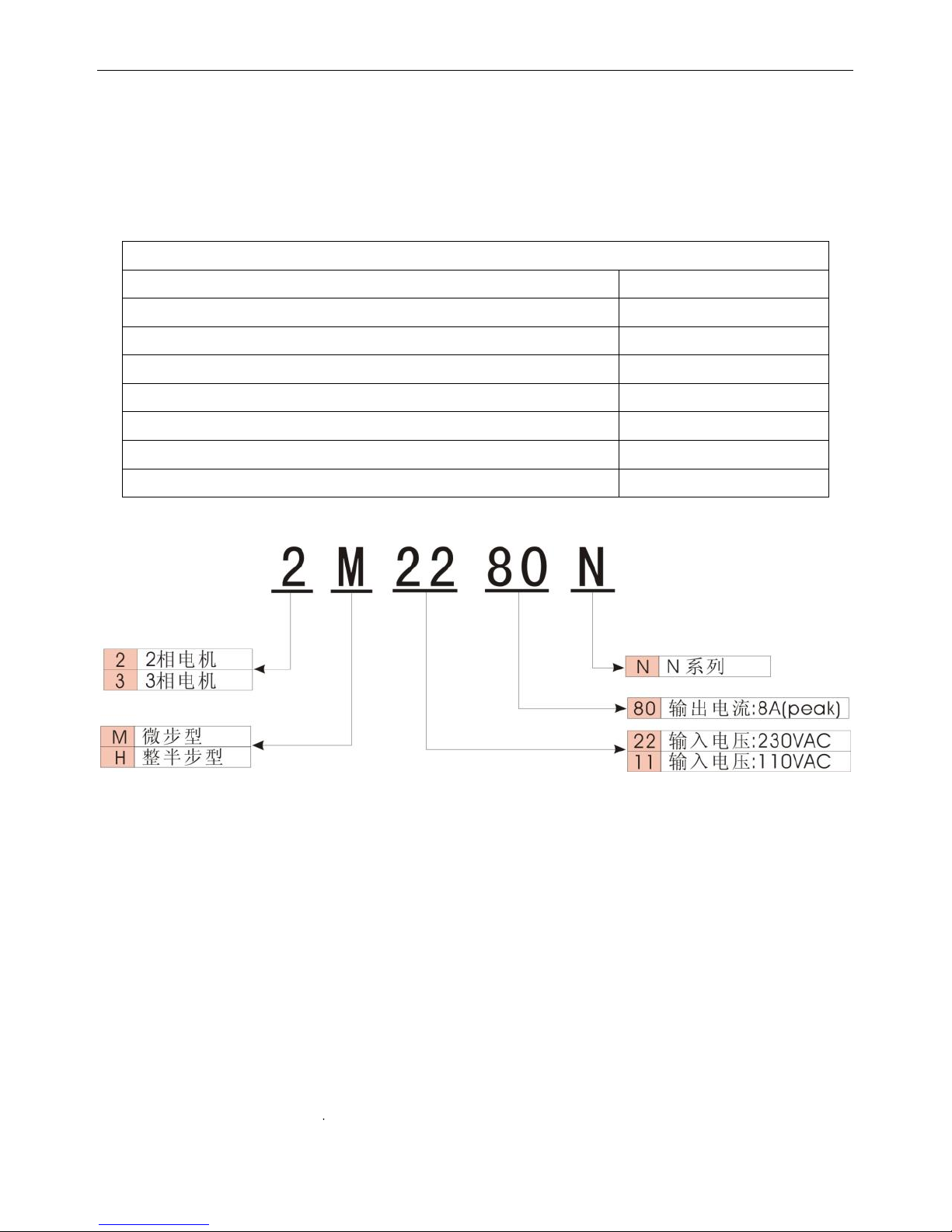
2.2 产品型号说明 ........................................................................................................3
2.3 产品概述 ................................................................................................................3
2.4 产品特点 ................................................................................................................3
2.5 产品功能 ................................................................................................................4
2.6 应用领域 ................................................................................................................4
第三章 产品参数与安装 .............................................................................................5
3.1 产品参数 ................................................................................................................5
3.2 接线端子说明 ........................................................................................................5
3.3 接线图示 ................................................................................................................6
3.4 控制信号时序图 ....................................................................................................8
3.5 拨码开关设置 ........................................................................................................9
3.6 驱动器的安装 ......................................................................................................10
第四章 常见问题及解答 ........................................................................................... 11
4.1 驱动器指示灯显示指南 ...................................................................................... 11
4.2 驱动器及步进电机常见问题及解答 ................................................................... 11
N 系列多功能细分步进电机驱动器使用手册版本说明
涉及产品:2M2280N 及 2M1180N 步进电机驱动器。
版本:V1.3
日期:2013 年 11 月 08 日
版本历史记录
版本
日期
更改内容
V1.0
2009-3-27
V1.1
2009-4-24
LED 指示状态描述
V1.2
2011-10-13
添加软件功能
V1.3
2013-11-08
使用公司新地址

使用手册
2
第一章 安全事项
为了避免人身伤害和财产损失,请在调试及使用驱动器前仔细阅读以下安全信息。
以下安全措施必须严格遵守:
仔细阅读产品使用手册。
严格遵守安全守则。
2M2280N 驱动器正常工作时内部将有 300VDC 左右的高压,2M1180N 驱动器在正常工
作时内部将有 150VDC 左右的高压,在切断驱动器电源 60 秒内,驱动器仍然存在高压,
请等驱动器的电压降到安全范围内,再进行接线或检查,否则可能遭到电击。
请勿在驱动器及电机工作时进行接线,否则可能遭到电击。
请勿在通电后或驱动器运行时拆开驱动器外壳,否则可能遭到电击。
为了避免人身伤害和财产损失,只有具有相关专业知识的人员才可以对驱动器进行操
作。
安装过程中请遵守相关技术规范和电气安装标准。必须把驱动器良好地接地,接地电缆
的截面积不小于 1.25 毫米。
请不要把任何物体放入驱动器内,否则可能造成驱动器损坏。
驱动器出现故障需要检修时,请将驱动器送回检修中心。私自打开驱动器或不正确的操
作会损坏驱动器。未经允许,私自打开驱动器外壳的情况下保修作废。
在废弃驱动器的时候,请按照工业废弃物的标准来处理,以免造成环境的污染。
声明:
把此驱动器应用于直接涉及人身安全的机械设备(核动力控制、医疗设备、卡车、火车、
飞机、如乐和安全防护设备等)时,必须安装防范的安装设备,避免出现可能发生的人
身伤害。
电子设备并非永久可靠!机器设备必须有足够的安全措施,在驱动器失灵的情况下保证
人员及设备本身安全。安装或使用驱动器的客户必须自己承担因为机器故障及错误操作
驱动器造成的损失。
2M1180N/2M2280N 步进驱动器
3
第二章 产品概述
2.1 产品确认
收到产品后,请仔细核对以下项目:
请确认驱动器型号与订购的型号是否一致。
打开产品包装后,请确认产品有无损坏或缺少零件等异常情况。
请确认驱动器上所有固定螺丝都是牢固的。
请按产品清单核对您收到的产品,如有缺少请及时联系我公司客服人员。
产品清单
物品
数量
2M2280N 驱动器或 2M1180N 驱动器
1 台
产品服务指南
1 张
驱动器使用手册
1 本
合格证
1 张
2kΩ 金属膜插件电阻
3 个
长 10mm 直径φ 10 绝缘端子
4 个
长 15mm 直径φ 12 绝缘端子
4 个
2.2 产品型号说明
2.3 产品概述
N 系列步进电机驱动器是步科电气最新推出的一种采用 DSP 单片机作为控制核心,使用矢
量电流控制算法的高细分步进电机驱动器,适合驱动各种品牌的两相混合式步进电机。由于
采用了先进的矢量控制算法,大幅度降低了电机运转的噪声和振动,使得步进电机运转时的
噪声和平稳性接近于伺服电机的水平。全新的散热器设计方式使驱动器在实现结构紧凑小巧
的前提下,仍然能够满足严格的安规要求。
2.4 产品特点
高性能,低价格,多功能。
2M2280N 采用 187V~253V 宽电压供电,可直接接入单相 220V 交流电网,减免变压器
费用。
具有电机参数自动适应功能,保证发挥各类电机的最大性能。
具有驱动器试运行功能。
具有相位记忆功能。
支持单/双控制脉冲输入。
光耦隔离 ERR 故障信号输出功能,实现与上位机的交互。

使用手册
4
静止 1.5S 之后驱动器输出电流自动减为当前值的一半。
光耦隔离信号输入,脉冲响应频率最高可达 400KHZ。
12 档细分,最高可达 128 细分。
具有过压,欠压,过流,过热,错相保护功能。
具有微步平滑滤波,可以对输入脉冲进行动态平滑,减少电机运动瞬变,使电机运行更
加平滑。
2.5 产品功能
2M2280N 步进驱动器采用了 DSP 单片机作为控制核心,大大地丰富了驱动器的应用功能,
同时智能化的固件设计,免去了烦琐的功能设置步聚,让您轻松获得电机的最佳性能!
电机自适应功能:驱动器能够自动检测所带电机的电气参数(如电感与电阻),实时跟
踪电机状态,并根据所检测到的电机状态调节自身参数适应,以达到最佳的驱动效果。
如果驱动器不是第一次驱动电机,请先在不接电机线的情况下让驱动器空载启动,此时
驱动器会清除以前存储在驱动器内的旧有的电机参数。断电并接上电机线后再重新上
电,驱动器会自动测出当前电机的最合适驱动参数。
相位记忆功能:驱动器在电机断电时,会保存电机断电时的相位。这样可以避免在某些
应用场合下驱动器上电时电机的抖动造成误差。每更换一次电机,或在机器停止后转动
电机会使保存的相位失效。
自动半流功能:在电机停止转动并锁紧 1.5 秒后,驱动器会自动把电机的相电流调整为
当前值的一半,以降低电机的发热,理论上能降低至 25%。
试运行功能:驱动器设置为此状态时,会自动以 60RPM 的速度驱动电机,此时的电流
输出为设定值,细分设置无效。此功能用于检验驱动器状态是否正常。
单/双脉冲兼容输入:驱动器的控制信号输入口支持“脉冲+方向” (PLS+DIR)控制信
号及双脉冲(CW/CCW)控制信号输入。
过压报警功能:2M2280N 驱动器会在内部母线电压超过 395VDC 的时候, 2M1180N 驱
支会在内部母线电压超过 187VDC 的时候,进入高压报警状态。此时应及时切断电源,
重新启动驱动器可清除此报警。如果频繁出现过压报警,建议调低输入电压,或采用带
吸收功能的驱动器。
过流报警功能:在电机或驱动器出现短路,接错线等情况下,驱动器会产生过流保护,
以免意外情况下的大电流损坏驱动器,出现过流报警时应及时切断电源,并检查电机的
接线。重新启动驱动器可清除此报警。
欠压报警功能:2M2280N 驱动器在内部母线电压低于 200VDC 的时候,2M1180N 驱动
器在内部母线电压低于 90VDC 的时候,驱动器进入欠压报警状态,欠压报警时重新启
动驱动器可以消除此报警。
过热报警功能:驱动器会在其内部温度达到 75 度时,进入过热报警状态。
错相保护功能:当驱动器与电机间的连线出错时,驱动器会进入错相报警状态,重新按
符合要求的接线方式接线,可以清除此报警。
2.6 应用领域
适合各种大中型自动化设备和仪器,如雕刻机,贴标机,切割机,数控机床,绘图仪等,
是要求实现低振动,小噪声,高精度,高速度的用户的理想选择。
推荐配套使用 KINCO 系列 110 及 130 型步进电机,以达到最佳控制效果。
2M1180N/2M2280N 步进驱动器
5
第三章 产品参数与安装
3.1 产品参数
在使用驱动器前,请务必详细了解驱动器参数,并确保驱动器工作在符合要求的供电环
境与应用环境中!
表 1 驱动器电气参数表
参数
描述
输入电压
2M2280N:单相交流 220V AC +/-15%(50Hz)( 187VAC~253VAC)
2M1180N:单相交流 77V AC~123VAC,( 50Hz)
相电流(峰值)
4.5A,5A,5.5A,6A,6.5A,7A,7.5A,8A 共 8 档
细分档
2/4/5/8/10/16/20/32/50/64/100/128, 共 12 档
适用电机
110,130 型步进电机
输入信号
PLS(CW)/DIR(CCW)/FRE 三个控制信号端口,电流范围为:6~16 mA
信号输入方式
脉冲+方向(PLS+DIR)/正反向脉冲(CW/CCW)
输出信号
ERR,集电极开路输出
自动半流
自动半流等待时间为 1.5s,相电流值减小 50%
保护电路类型
过压报警,欠压报警,过流保护,过热保护
吸收电路
*
用于吸收电机反馈的能量,此功能需要订制
表 2 使用环境及参数表
冷却方式
强制风冷
使用环境
使用场合
避免有大量金属粉尘,油雾或腐蚀性气体
使用环境湿度
<85%, RH(不能结露和有水珠)
使用环境温度
0℃~+40℃
保存温度
-20℃~+70℃
重量(净重)
1.5Kg
外形尺寸
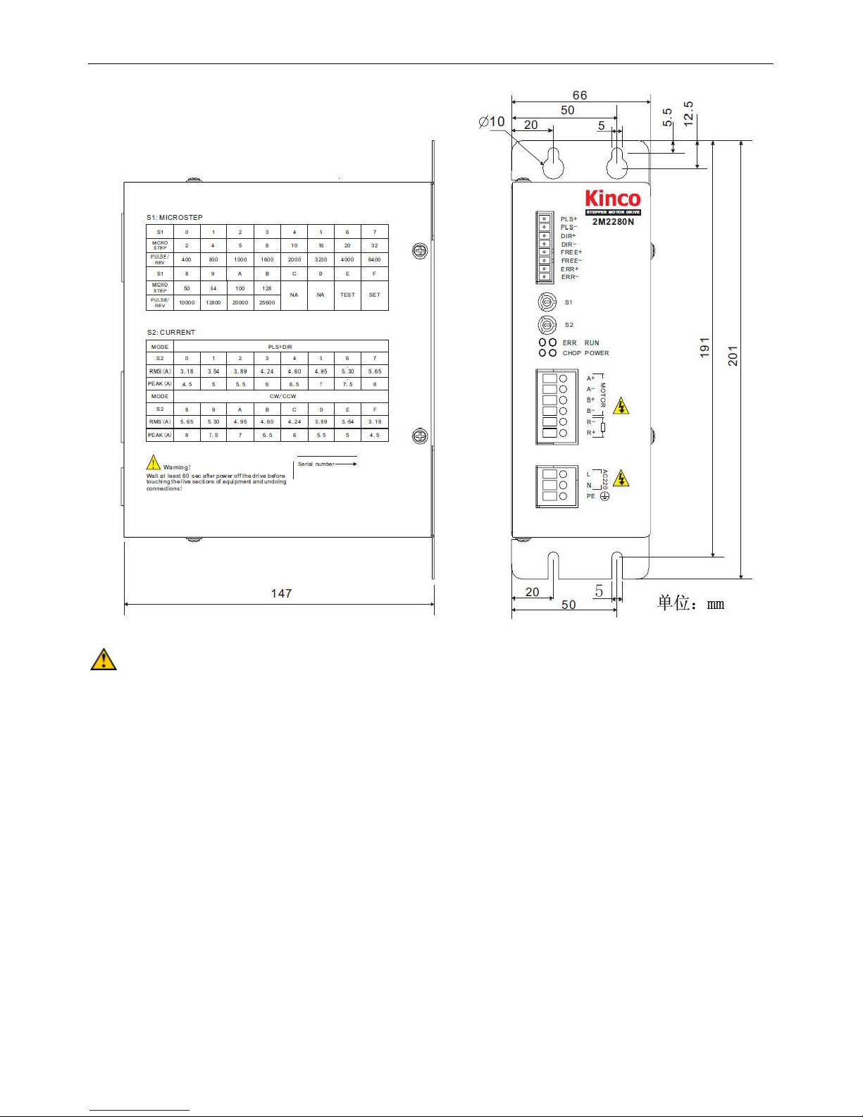
201mm×147mm×66mm
防护等级
IP20
3.2 接线端子说明
驱动器的接线端子分为控制信号端,电机动力线端,电源输入端三部分。控制信号端口
可以接受差分信号,单端共阴及共阳信号,内置高速光耦,可以隔离外部环境对驱动器的干
扰。以下详细说明驱动器接口端子的定义。
表 3 控制信号端口定义
信号
功能描述
PLS+(CW+)
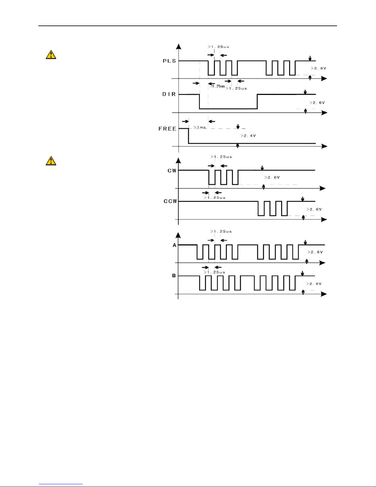
脉冲信号。在单脉冲控制模式下,此信号为脉冲控制信号,上升沿有效。
在双脉冲控制模式下,此信号为正转控制信号,上升沿有效。
高电平时间应不小于 1.25uS,以保证内部光耦的可靠响应。
脉冲信号的最高输入频率为 400KHz
PLS-(CW-)

使用手册
6
DIR+
(CCW+)
在单脉冲模式下,此信号为方向控制信号,驱动器通过检测此信号的电
平设置电机运转方向。此信号有效值为脉冲信号上升沿时刻。
在双脉冲模式下,此信号为反转控制信号,上升沿有效。
为了保证内部光耦的可靠响应,双脉冲高电平时间应不小于 1.25uS。
脉冲信号的最高输入频率为 400KHz
DIR(CCW-)
FREE+
此信号为脱机信号,此信号为高电平时,驱动器切断电机供电,电机转
子处于自由状态(脱机)。
FREE-
ERR+
报警输出信号。此信号端口为集电极开路的光耦输出,当驱动器出现异
常报警或断电时,此信号端口的光耦无输出(电平由外接电路决定)。
端口最大允许输入电压为 30VDC,最大供电电流为 10mA。
ERR-
表 4 强电端口定义
信号
功能描述
A+
电机 A 相接入口。A+,A-互换可改变电机方向。
A-
B+
电机 B 相接入口。B+,B-互换可改变电机方向。
B-
R+
吸收(刹车)电阻接入口。
R-
表 5 电源输入端口定义
L
驱动器电源输入接口,2M2280N 驱动器允许直接接入单相 220V 交流供
电网。
N
PE
驱动器接地端子。
3.3 接线图示
控制信号一般方式接法

2M1180N/2M2280N 步进驱动器
7
控制信号双绞方式接法
驱动器的所有控制信号的输入电路中都采用了可靠的光耦元件进行隔离,可以减少外部
电气噪声对于本驱动器的干扰。
图中 R0 为外部限流电阻,用于限制驱动器的输入信号电流,在控制信号为 24VDC 时,
可接入 2K 的电阻,如果控制信号为 12VDC 时,则可接入 1K 的电阻,必须保证驱动器
的输入口电流在 6~16mA 范围,否则电流过小可能会使信号失效,电流过大会损坏设备。
ERR 信号为集电极开路输入,输要外接电源,最大外接电压不超过 30V。ERR 信号端口
严禁将电源反接,否则会损坏端口。
如果现场应用有较强干扰时,控制信号推荐用双绞方式接线,以减少干扰源对控制信号的
干扰。

使用手册
8
3.4 控制信号时序图
控制信号注意事项:
输入脉冲的最高频率为 400KHz。
方向信号禁止在脉冲信号上升期间变化。
脱机信号必须提前脉冲信号 1ms 建立。
驱动器接线注意事项:
驱动器布线时,为了避免驱动器受到干扰,请遵循强电(电机相线与电源线)与弱电隔
离布线的原则(最少要相距 10 厘米)。
驱动器的控制信号接线建议采用屏蔽双绞线,屏蔽层必须可靠接地(驱动器与设备的真
实地)。
驱动器的电机动力线及电源线由于要承受较大的电流,因此建议使用的导体截面积不小
于 1.5mm2,必要时视电流大小选用更大截面积的导线。
严禁带电接拨线,否则可能造成设备损坏及人身伤害。特别注意电机在锁紧状态,电机
动力线上仍然具有较大的电流,强行接拔线会造成设备损坏及人身伤害。
电机动力线及驱动器电源输入线接入端子的裸线长度应为 10mm 左右,裸线太短会造成
接触不良,裸线太长有电击危险。电机动力线套上绝缘端子,可减小与端子的接触电阻。

2M1180N/2M2280N 步进驱动器
9
3.5 拨码开关设置
驱动器共配置有两个圆型拨码开关 S1、S2,实现驱动器的细分选择,电流值选择,试运
行状态使能及单/双脉冲控制信号选择。
S1,Micro-step:细分与试运行功能选择开关
S1
0 1 2 3 4 5 6
7
Micro step
2 4 5 8 10
16
20
32
Pulse/rev
400
800
1000
1600
2000
3200
4000
6400
S1
8 9 A B C D E
F
Micro step
50
64
100
128
NA
NA
TEST
NA
Pulse/rev
10000
12800
20000
25600
S2,Current:电流与单双脉冲选择开关
Mode
PLS+DIR
S2
0 1 2 3 4 5 6 7 Rms(A)
3.18
3.54
3.89
4.24
4.60
4.95
5.30
5.65
Peak(A)
4.5 5 5.5 6 6.5 7 7.5
8
Mode
CW/CCW
S2
8 9 A B C D E
F
Rms(A)
5.65
5.30
4.95
4.60
4.24
3.89
3.54
3.18
Peak(A)
8
7.5 7 6.5 6 5.5 5 4.5
工作模式选择
工作模式
S1
S2
操作方式
试运行
E
0~F
驱动器断电时,把 S1 设为 E,S2设为 0~F(电流值按需要设定),
再把驱动器通电,电机将自动以 60RPM 运行。
PLS+DIR
0~B
0~7
驱动器断电时,把 S1 设为 0~B,S2 设为 0~7(值按需要设定)。
驱动器通电后就工作在 PLS+DIR(脉冲加方向)控制模式
CW/CCW
0~B
8~F
驱动器断电时,把 S1 设为 0~B,S2 设为 8~F(值按需要设定)。 驱
动器通电后就工作在 CW/CCW(双脉冲)控制模式。
开启自动半流
F
C
驱动器断电时,按照需要的工作模式设置驱动器 S1,S2 开关,设
置完后,打开驱动器电源,此时指示灯状态为:RUN 灯 闪烁,
POWER 灯常绿,ERR灯常为红色,CHOP 灯关闭,表示设置成功,
断开驱动器,重新设置所需的细分及电流值即可以正常使用。
关闭自动半流
F
D
开启微步平滑
滤波器
F
F
关闭微步平滑
滤波器
F
E
注意:
S1 开关设置为 NA 状态为特殊指令,设置为 NA 状态时驱动器会产生报警。设置到正确
位置可清除此报警。
设置拨码开关状态时,应选用大小合适的一字螺丝刀进行设置,否则会造成拨码开关损
坏。也请不要对拨码开关施加轴向力,否则会造成拨码开关损坏。
驱动器出厂时,设了默认工作模式:自动半流使能,微步平滑滤波器使能。
如果现场应用对电机响应速度要求很高,例如数控制机床应用,建议关闭微步平滑滤波
器,以缩短电机到达位置的时间。
使用手册
10
3.6 驱动器的安装
安装注意事项:
建议将驱动器正立侧面安装,以保证驱动器的安装环境通风顺畅,特别是驱动器的通风
口,绝不能有遮盖物,否则会使驱动器频繁过热报警而影响正常使用。
为保证驱动器的良好散热,两台驱动器之间的安装距离应不少于 50mm。
本驱动器的防护等级为 IP20,请将驱动器置于符合要求的室内环境及电气柜中运行,否
则可能导致驱动损坏及人身伤害。
当驱动器频繁出现过热报警时,表示需要对驱动器进行加强散热,可在靠近驱动器处安
装风扇,强制冷却散热,以确保驱动器在可靠的工作温度范围内工作。

2M1180N/2M2280N 步进驱动器
11
第四章 常见问题及解答
4.1 驱动器指示灯显示指南
N 系列步进驱动器拥有完善的保护电路,最大限度地确保驱动器的安全。同时,丰富的指
示灯状态指示,使你能够时刻掌握驱动器的工作状态!
指示灯状态定义:
报警
指示灯
解决办法
Power
Run
Error
Chop
内部不通电
熄灭
熄灭
熄灭
熄灭
检查电源
单片机复位
开启
开启
开启
开启
硬件出错
开启
熄灭
开启
开启
检查电机接线
电机相间出错
开启
熄灭
开启
快闪
检查电机接线
过流报警
开启
熄灭
快闪
熄灭
检查电机接线
过压报警
开启
熄灭
快闪
快闪
增加减速时间或降低电压
过热报警
开启
熄灭
慢闪
熄灭
驱动器冷却后再上电
欠压报警
开启
熄灭
开启
熄灭
检查电源功率是否足够
拨码开关出错
开始
慢闪
开启
熄灭
确认开关在正确位置
电机线未接
开启
熄灭
开启
慢闪
检查电机接线
正常运行
开启
开启
熄灭
熄灭
试运行
开启
慢闪
熄灭
熄灭
制动
开启
开启
熄灭
开启
应考虑使用吸收功能
注意:
慢闪指闪动的频率为 0.5Hz,快闪指闪动频率为 5Hz。
驱动器出现的所有报警都需要断电并重新启动驱动器才能清除。
在任何报警情况下都应及时关断电源,确认驱动器不带电后再触摸驱动器及电机。
除了正常运行,试运行,吸收这三种情况外,驱动器 ERR 信号都会输出有效电平。
如果出现未在表中标明的指示灯状态,请与我们的客服人员联系。
4.2 驱动器及步进电机常见问题及解答
1、步进电机的外表温度允许达到多少?
步进电机温度过高首先会使电机的磁性材料退磁,从而导致力矩下降乃至于失步,因此电
机外表允许的最高温度应取决于不同电机磁性材料的退磁点;一般来讲,磁性材料的退磁
点都在摄氏 130 度以上,所以步进电机外表温度在摄氏 80-90 度完全正常。
2、步进电机的输出功率怎样计算?
步进电机的输出功率随转速变化而不同,一般用力矩来衡量。步进电机的输出功率计算公
式为:P=,其中2n/60,为角速度,为电机此时的输出力矩。
、驱动器的细分功能有什么作用?
步进驱动器的细分功能是一种电子阻尼技术。有三个明显的作用:
A.因为对步距角进行了细分,因此提高了控制精度。
B.细分是抑制步进电机低频振荡的最好方法。
C.可以在一定程度上提高电机的力矩。

为全球客户提供中国人的自动化解决方案
深圳市步科电气有限公司
Kinco Electric (Shenzhen) Ltd.
地 址:深圳市南山区高新科技园北区朗山一路 6 号一栋(518057)
电 话:86-755-26585555
传 真:86-755-26616372
http://www.kinco.cn
Email: sales@kinco.cn

Kinco
®
N Series Stepper Motor
Driver
2M1180N/2M2280N
User
Manual
Version:
V1.33


2M1180N/2M2280N Stepper Motor Driver
1
Contents
Chapter 1 Safety
Precautions..............................................................................................................................
2
Chapter 2 Product
Overview...............................................................................................................................
3
2.1 Product Acceptance
.........................................................................................................................................
3
2.2 Product Model
Description ...........................................................................................................................
3
2.3 Product Overview
.............................................................................................................................................
3
2.4 Product
Features ...............................................................................................................................................
4
2.5 Product
Functions..............................................................................................................................................
4
2.6 Scope of
Application..........................................................................................................................................
.5
Chapter 3 Product Parameters and
Installation ............................................................................................
6
3.1 Product Parameters
..........................................................................................................................................
.6
3.2 Description of Wiring
Terminal .....................................................................................................................
6
3.3 Wiring
Diagram ...................................................................................................................................................
8
3.4 Time Sequence Diagram of Control
Signal ...............................................................................................10
3.5 DIP Switch
Settings ..........................................................................................................................................
.11
3.6 Installation of the
Driver ................................................................................................................................
13
Chapter 4
FAQ.............................................................................................................................................................
15
4.1 Indications of Driver Indicators
..................................................................................................................
15
4.2 FAQ on the Driver and Stepper Motor
.......................................................................................................
16
Release Notes on N Series Multi-functional Micro-step Stepper Motor Driver
User Manual
Products involved: 2M2280N and 2M1180N stepper motor drivers.
Version: V1.3
Date: Nov, 08, 2013
Revision
History
Version
Date
Description
V1.0
2009-4-2
V1.1
2009-4-24
V1.2
2011-10-13
V1.3
2013-11-08
Update new factory
address

User Manual
2
Chapter 1 Safety Precautions
For the sake of personal safety and avoidance of property loss, please read these safety
precautions carefully before test running and use of the driver.
The following safety measures must be strictly followed:
Read this user manual carefully.
Observe safety precautions strictly.
After being powered on, the voltage in side 2M2280N driver is about 300VDC and the
voltage inside 2M1180N driver is about 150VDC. The high voltage still exists 60
seconds after the power supply is cut off . Before performing any wiring or check
operation, use a multimeter to verify that the voltage on the driver terminals is safe;
otherwise, the electric shock may occur.
Never connect wires while the driver and the motor are working; otherwise, the electric
shock may occur.
Do not remove the housing of the driver when the power is on or the driver is working;
otherwise, the electric shock may occur.
To avoid personal injury and property loss, only qualified and service-trained personnel
can operate the driver.
Follow related technical specifications and electric installation standards during
installation. The driver must be securely grounded with the cross section of the ground
cable not less than 1.25 mm2.
Do not insert any object into the driver, which may cause damage to the equipment.
If any fault occurs to the driver, please return the driver to the maintenance and repair
center. Opening the driver without authorization or improper operation may cause
damage to the driver. Removing the enclosure of the driver without authorization will
void the warranty.
The waste driver shall be disposed of as industrial waste to avoid environmental
pollution.
Statement:
When this driver is applied in some mechanical instruments where personal safety is
directly involved (e.g. nuclear power control, medical device, truck, train, airplane,
amusement and safety devices), be sure to install proper fault-proof devices to avoid
the possibility of personal injury.
Electronic devices are not permanently reliable! Adequate safety measures must be
taken to ensure personal and equipment safety in case of a failure. The users must be
liable for any loss resulting from equipment fault or misoperation of the driver.

2M1180N/2M2280N Stepper Motor Driver
3
Chapter 2 Product Overview
2.1 Product Acceptance
Upon receiving the product, please check the following items:
Make sure the driver model is consistent with that ordered.
Unpack the product and make sure it is free from damage and no part is missing.
Make sure all set screws in the driver are securely tightened.
Check the received product against the packing list and contact our customer service
center in time if any part is missing.
Packing List
Article
Qty.
2M2280N driver or 2M1180N driver
1 pcs
Product Services Directory
1 pcs
User Manual
1 pcs
Certificate of Conformity
1 pcs
2kΩ metal film DIP resistor
3 pcs
Length 10mm diameter φ10 insulated terminals
4 pcs
Length 15mm diameter φ12 insulated terminals
4 pcs
2.2 Product Model Description
2.3 Product Overview
N series drivers are the latest high-subdivision stepper motor drivers launched by Kinco
Electric (Shenzhen) Ltd. With the DSP single-chip microcomputer as the control core,
these products adopt vector current control algorithm and are suitable for driving
2-phase hybrid stepper motors under various brand names. The application of
advanced vector control algorithm reduces remarkably the noise and vibration of the
motors during operation, and enables the stepper motors to deliver a noise and stability
level comparable to that of servo motors. The brand-new radiator design enables the
drivers to meet the strict safety requirements while keeping a compact structure.

User Manual
4
2.4 Product Features
High performance, low cost, and diversified functions.
2M2280N adopts 187V~253V wide-range power supply and can be connected directly
with single-phase 220V AC power to save the cost of a transformer.
Automatic parameter adjustable regulation.
Supporting driver test running function.
Supporting phase memory function.
Supporting PLS+DIR and CW/CCW control signal.
Supporting optocoupler isolation ERR signal output function and interaction with the
upper computer.
Output current of the driver automatically reduces by a half in 1.5S after the driver gets
static
Opto-isolation signal input, with pulse response frequency up to 400 KHz.
Simple and easy subdivision and current setting.
12 micro-step value, the maximum micro-step value is 128.
With the protection function of over-voltage, under-voltage, over-current, overheat.
With micro-step smoothing filter, the input pulse can be dynamically smooth and
reduce the transient motor sport, motor run more smoothly.
2.5 Product Functions
2M2280N stepper motor drivers adopt DSP single-chip microcomputer as its control core,
which greatly enriches their applications. Meanwhile, the intelligent firmware design frees
the users from complicated function setting steps and delivers the optimum performance
of the motors easily.
Motor auto adaptation: The driver can automatically detect the
electrical
parameters
(e.g., inductance and resistance) of the motor connected with the driver, trace the
status of motor in real time, and automatically adjust the driver parameters
according to the detected motor status to deliver the optimum driving performance.
If it is not the first time for the driver to drive the motor, please run the driver under
no load before connecting the motor. Then, the driver will clear the motor
parameters stored before. Turn off the power, connect the motor, and turn on the
power again; the driver will automatically detect the optimum drive parameters for
the current motor.
Phase memory: The driver will keep the phase of the motor in the case
of power
failure with the motor. Therefore, it prevents the error caused by motor jitter upon
power-on on some application occasions. The kept phase will be lost if the motor is
replaced or the motor still rotates after the driver stops.
Automatic half current: After the motor stops rotation and locks tight, the driver
will
reduce the phase current of the motor by a half in 1.5 seconds to cut down the
heat generated by the motor, theoretically, by 25%.
Test running: If the driver If the driver is set to this status, it will autoatically drive

2M1180N/2M2280N Stepper Motor Driver
5
the motor at a speed of 60RPM. At this time, the output current is the set value and
the subdivision setting becomes invalid. This function is used to check whether the
driver status is normal.
PLS+DIR and CW/CCW compatible input: The control signal input port of
the driver supports “PLS + DIR” control signal and “CW/CCW” control signal input.
Over-voltage alarm: The driver will generate a high-voltage alarm if the internal
bus voltage exceeds 395 VDC in the case of the 2M2280N driver or 187VDC in the
case of the 2M1180N driver. At this time, turn off the power supply in time and reboot
the driver to clear the alarm. If the over-voltage alarm occurs frequently, it is
recommended that the input voltage be tuned down or a driver with absorption
function be adopted.
Over-current alarm: The driver will activate the over-current protection function
in
the
case of short-circuit or wrong wiring of the motor or driver, so as to prevent the
damage to the driver. In this case, turn off the power supply in time and check the
wiring of the motor. To clear the alarm, reboot the driver.
Under-voltage alarm: The driver will generate a low-voltage alarm if the
internal
bus
voltage goes below 200 VDC in the case of the 2M2280N driver or 90VDC in the
case of the 2M1180N driver. To clear the alarm, reboot the driver.
Overheat alarm: The driver will generate a overheat alarm if the internal
temperature reaches 75℃.
Miss-connection protection: The driver will generate a miss-connect alarm if
the wiring between the driver and the motor is wrong. To clear the alarm, reconnect
the wires correctly.
2.6 Scope of Application
The drivers are applicable to various large and medium automation equipment and
instruments, including engraving machines, labeling machines, cutting machines,
numerical control machine tools, and plotters. They are ideal choices for users in search of
low vibration, low noise, high accuracy, and high speed.
To achieve the optimum performance, KINCO 110 and 130 series stepper motors are
recommended.

User Manual
6
Chapter 3 Product Parameters and Installation
3.1 Product Parameters
Please learn carefully the driver parameters before use. Make sure the power supply and
operating environment conform to relevant requirements.
Table 1 Electrical Specifications
Parameter
Description
Input voltage
2M2280N: Single-phase 220V AC +/-15% (50Hz)(187VAC~253VAC)
2M1180N: Single-phase 77V AC~123VAC, (50Hz)
Phase
current(peak)
4.5A,5A,5.5A,6A,6.5A,7A,7.5A,8A
Micro step
2/4/5/8/10/16/20/32/50/64/100/128
Input signal
Three control signal ports: PLS(CW)/DIR(CCW)/FRE; current range:
6~16 mA
Signal input
method
PLS+DIR; CW/CCW
Output signal
ERR, open collector output
Automatic half
current
Waiting time for automatic half current: 1.5s; phase current decreased
by 50%
Protection
Over-voltage, under-voltage, over-current, and overheat protection
Absorbing circuit*
Need customize, used to absorb the energy feed back by the motor
Table 2 Operating Environment
Cooling method
Forced air cooling
Environment
Operation environment
Avoid the environment with great amount of
metallic powder, oil mist, or erosive gases.
Operation humidity
<85%, RH (non-condensing or water drops)
Operation temperature
0℃~ +40℃
Storage temperature
-20℃ ~ +70℃
Weight (net)
1.5Kg
Dimensions
201mm× 147mm× 66mm
Ingress protection
IP20
3.2 Description of WiringTerminal
Wiring terminals of the driver are divided into three types: control signal port, motor power
cable port, and power input port. Control signal port can receive differential signal,
single-ended common-cathode and common-anode signals, and can prevent the interference
of ambient environment on the driver with the built-in high-speed optocoupler. The twisted
pairs are recommended as signal lines for enhanced interference immunity in environments
with strong electromagnetic interference. The definitions of the driver ports are detailed
below.

2M1180N/2M2280N Stepper Motor Driver
7
Table 3 Definition of Control Signal Port
Signal
Functional Description
PLS+(CW+)
Pulse signal. In the PLS+DIR control signal mode, the signal is the pulse
control signal and the rising edge is effective.
In the CW/CCW control signal mode, the signal is the forward rotation
control signal and the rising edge is effective. The high-level time shall
not be less than 1.25uS to ensure reliable response of the internal
optocoupler.
The maximum input frequency of the pulse signal is 400 KHz
PLS-(CW-)
DIR+(CCW+)
In the PLS+DIR control signal mode, the signal is direction control signal,
and the driver sets the rotation direction of the motor by detecting the
level of this signal. The signal value of the effective moment in the
rising edge of pulse signal.
In the CW/CCW control signal mode, the signal is the reverse rotation
control signal and the rising edge is effective. To ensure reliable response
of the internal optocoupler, the high-level time in this mode shall not be
less than 1.25uS.
The maximum input frequency of the pulse signal is 400 KHz
DIR-(CCW-)
FREE+
This signal is offline signal. If the signal is at a high level, the driver turns
off the power supply for the motor, and the motor rotor turns into Free
status (Offline). Adequate measures must be adopted to prevent the
motor from causing equipment damage or personal injury when it is in
the offline status.
FREE-
ERR+
Alarm output signal. This signal port is the optocoupler output port for
open collector. When the driver has an exception alarm or power failure
alarm, this signal port have not outputs((level determined by the external
circuit).
For this port, the maximum allowable input voltage is 30V DC and the
maximum supply current is 10 mA.
ERR-

User Manual
8
Table 4 Definition of Strong Current Port
Signal
Functional Description
A+
Phase A of motor. The switching between A+ and A- can change
motor rotation direction.
A-
B+
Phase B of motor. The switching between B+ and B- can change
motor rotation direction.
B-
R+
Absorbing(Break)resistor
port.
R-
Table 5 Definition of Power Input Port
ACN+
Power input ports for the driver. The 2M2280N driver can be
connected to a single-phase 220V AC source directly.
ACL-
PE
Grounding terminal of the driver
3.3 Wiring Diagram
General Way Control Signal Wiring Diagram

2M1180N/2M2280N Stepper Motor Driver
9
Twisted-pair Way Control Signal Wiring Diagram
The input circuits of all control signals of the driver have been reliably isolated
through optocoupler elements, which minimize the interference from external
electrical noises.
In the figure, R0 is an external current limit resistor used to curb the input
si gnal
current of the driver. When control signal is at 24VDC, a 2K resistor can be connected;
when the control signal is at 12VDC, a 1K resistor can be connected. The current at
the input port of the driver must be within 6~16 mA; otherwise, the current too less
may cause signal loss,much more current will damage the equipment.
ERR signal is open collector output and requires an external power supply.
The
maximum external voltage cannot exceed 30V. Never connect the ERR signal port in
reversed polarity; otherwise, it may cause damage to the port.
if driver work in a strong interference field,the control signal wiring is recommended
twisted-pair way,this can reduce the interference signal source interfere control
signal.
User Manual
10
3.4 Time Sequence Diagram of Control Signal
Precautions on Control
Signal:
The maximum frequency of
the input pulse is 400 KHz.
Disable direction signal
change during pulse
signal rise time.
An offline signal shall be set
up 1ms earlier than a pulse
signal.
Precautions on Wiring:
To avoid interference on
the driver, the strong
current cables (phase wires
and power cables of the
driver) shall be isolated
from the weak current
cables (for a distance of at
least 10cm) when
connecting wires for the
driver.
It is recommended that the
twisted pairs be adopted
for control signal cables for the driver, and the shielding layer be grounded reliably (to
the true ground of the driver and equipment).
Due to endurance of heavy current, conductors with cross-section no less
than1.5mm2 are recommended for the motor cabling, or even thicker ones as
appropriate.
Motor cabling put insulated terminals ,it can reduce the contact
resistance between motor and driver.
It is strictly forbidden to connect wires while the power is on; otherwise, it may
cause
equipment damage and personal injury. Please note that the power line of the
motor
still carries heavy current even if the motor is in the locked status. Pull out or
connect the wire forcibly may cause equipment damage and personal injury.
The length of bare wires at the inputs of the power line of the motor and the power
input cable of the driver shall be around 10mm; it may result in poor contact if the
length is too short and may cause electric shock if the length is too long.

2M1180N/2M2280N Stepper Motor Driver
11
3.5 DIP Switch Settings
The driver is configured with two round DIP switches S1 and S2, which are used for
macro-step value selection, current value selection, test running status enabling, and
PLS+DIR or CW/CCW control signal selection.
S1,Micro-step:
S1
0 1 2 3 4 5 6 7
Micro step
2 4 5 8 10 16 20 3
Pulse/rev
400
800
1000
1600
2000
3200
4000
6400
S1
8 9 A B C D E F
Micro step
50 64
100
128
NA
NA
TEST
NA
Pulse/rev
10000
12800
20000
25600
S2, Current:
Mode
PLS+DI
S2
0 1 2 3 4 5 6 7
Rms(A)
3.18
3.54
3.89
4.24
4.60
4.95
5.30
5.65
Peak(A)
4.5
5
5.5
6
6.5
7
7.5
8
Mode
CW/CCW
S2
8 9 A B C D E F
Rms(A)
5.65
5.30
4.95
4.60
4.24
3.89
3.54
3.18
Peak(A)
8
7.5
7
6.5
6
5.5
5
4.5
Mode select::
Mode
S1
S2
operation
Test running
E
0~F
When driver power off, set S1 on E,S2
among 0~F, motor will run at 60rpm after
power on.
PLS+DIR
0~B
0~7
When driver power off, set S1 among
0~B, S2 among 0~7, driver will run at
PLS+DIR mode after power on.
CW/CCW
0~B
8~F
When driver power off, set S1 among
0~B, S2 among 8~F, driver will run at
CW/CCW mode after power on.
Enable auto
half current
F
C
When driver power off, set S1 and S2 to
select mode, then power on driver, the
LED statue: RUN LED Blink, POWER LED
on, ERR LED on, CHOP LED off, this mean
mode have setted. After power off, set
micro step and phase current as normal
use.
Disable auto
half current
F
D
Enable step
smoothing filter
F
F
Disable step
smoothing filter
F
E

User Manual
Precautions on rotary switch:
S1 cannot be set to NA; otherwise, the driver will generate an alarm. In this case, turn
off the power, re-set the macro-step values, and turn on the power again to resume
normal.
To set the status of the DIP switch, choose an appropriate straight screwdriver; a
screwdriver of inappropriate size may cause damage to the DIP switch.
When setting the status of the DIP switch, do not apply an axial force; otherwise,
it may cause damage to the DIP switch.
Micro-step smoothing filter setting stored in driver EEPROM,driver will read the state
before working,to determine the Micro-step smoothing filter on or off.It’s enable as
default.

2M1180N/2M2280N Stepper Motor Driver
13
3.6 Installation of the driver
If the field application need motor response speed very very high, such as digital
control machine application,it recommend to disable mircro-step smoothing filter to
reduce the time of motor reach the location。
Precautions on Installation:
It is recommended that the driver be mounted on a side and kept in an upright
position, so as to maintain a well ventilated installation environment. Never block or
cover the air vents of the driver; otherwise, the normal use of the driver may be
prevented by possible frequent overheat alarms.
For better heat dissipation, two drivers shall be installed at a clearance of at least
50mm.
With an ingress protection class of IP20, the driver shall be installed in an
industry-compliant indoor switching cabinet; failure to do so may cause damage to
the driver or personal injury.
Enhanced heat dissipation is required if the driver generates overheat alarms

User Manual
frequently. A fan may be installed in a position close to the driver for forced cooling
and heat dissipation, so as to ensure the driver works in an allowable temperature
range。

2M1180N/2M2280N Stepper Motor Driver
15
Chapter 4 FAQ
4.1Indications of Driver Indicators
N series stepper motor drivers are equipped with complete protection circuits to protect their
safety to the greatest extent possible. In addition, the rich indications of indicators help the
user to learn the working status of the driver in time.
Indications of Indicators:
Alarm
Indicator
Motor Status
Power
Run
Error
Chop
Internal power failure
Off
Off
Off
Off
The motor power supply
disconnects and the motor shaft
releases
Single-chip
microcomputer
resetting
On
On
On
On
The motor power supply
disconnects and the motor shaft
releases
Hardware error
On
Off
On
On
The motor power supply
disconnects and the motor shaft
releases
Motor
phase-to-phase error
On
Off
On
Blink
quickly
The motor power supply
disconnects and the motor shaft
releases
Over-current alarm
On
Off
Blink
quickly
Off
The motor power supply
disconnects and the motor shaft
releases
Over-voltage alarm
On
Off
Blink
quickly
Blink
quickly
The motor power supply
disconnects and the motor shaft
releases
Overheat alarm
On
Off
Blink
slowly
Off
The motor power supply
disconnects and the motor shaft
releases
Under-voltage alarm
On
Off
On
Off
The motor power supply
disconnects and the motor shaft
releases
DIP switch error
On
Blink
slowly
On
Off
The motor power supply
disconnects and the motor shaft
releases
Motor cable not
connected
On
Off
On
Blink
slowly
The motor power supply
disconnects and the motor shaft
releases
Normal running
On
On
Off
Off
The motor runs normally
Test running
On
Blink
slowly
Off
Off
The motor runs normally
Braking
On
On
Off
On
The motor runs normally

User Manual
Note:
Blinking slowly means blinking at a frequency of 0.5 Hz, and blinking quickly means
blinking at a frequency of 5Hz.
To clear any alarm of the driver, it is necessary to disconnect the power supply and
then reboot the driver.
In the case of any alarm, it is necessary to disconnect the power supply in time, and
never touch the driver and motor when the power supply of the driver is on.
Except for the normal running, test running, and absorbing status, the driver ERR
signal will output a low level.
If any indication not covered in the above table occurs, please contact our customer
service personnel.
4.2 FAQ on the Driver and Stepper Motor
1. What is the maximum allowable surface temperature for a stepper motor?
The excessively high temperature will demagnetize the magnetic materials of a
stepper motor and as a result, cause lower torque or out of step of the motor.
Therefore, the maximum allowable surface temperature of a stepper motor depends
on the demagnetization point of different magnetic materials. In general, the
demagnetization point for magnetic materials is above 130℃, so it is normal if the
surface
temperature of
a stepper motor remains at 80℃ - 90℃.
2. How to calculate output power of a stepper motor?
The output power of a stepper motor varies with the rotation speed and is generally
measured by torque. The calculation formula for output power of a stepper motor
is: P=ω*M; whereω=2π*n/60, ω indicates the angular speed and M indicates the
output torque.
3. What is the subdivision function of the driver intended for?
The subdivision function of a stepper motor driver is a kind of electronic damping
technology. It has three distinctive functions:
A. It enhances the control accuracy due to the subdivision of step angles.
B. Subdivision is the best method to suppress the low-frequency oscillation of the
motor. C. It can enhance the motor torque to some extent.


To be the partner of your success
Kinco Electric (Shenzhen) Ltd.
Address:Building1, No.6 Langshan 1st Rd, Hi-tech Park North, Nanshan,
Shenzhen, China. 518057
Tel: 86-755-26585555
Fax: 86-755-26616372
http://www.kinco.cn
Email:sales@kinco.cn
 Loading...