


Kinco-KS series
1
CONTENT
CHAPTER 1 GENERAL INTRODUCTION........................................................................... 3
1.1 SUMMARY..............................................................................................................................3
1.2 PRODUCT LIST.......................................................................................................................3
1.3 ENVIRONMENTAL CONDITION............................................................................................... 4
CHAPTER 2 CPU MODULE INTRODUCTION.................................................................... 6
2.1 OVERVIEW............................................................................................................................. 6
2.1.1 Structure......................................................................................................................... 6
2.1.2 CPU Types......................................................................................................................6
2.2 FUNCTIONS............................................................................................................................ 8
2.2.1 CPU Status and LEDs....................................................................................................8
2.2.2 Programming port and serial port................................................................................ 10
2.2.3 CAN port......................................................................................................................10
2.2.4 Expansion modules.......................................................................................................11
2.2.5 High Speed Counter and High Speed Pulse Output.................................................... 12
2.2.6 Edge Interrupts............................................................................................................. 12
2.2.7 Data Retentive and Data Backup................................................................................. 12
2.2.8 Real-time Clock (RTC)................................................................................................ 13
2.2.9 Backup Battery.............................................................................................................13
2.3 WIRING DIAGRAM................................................................................................................14
2.4 DIMENSION..........................................................................................................................17
2.5 TECHNICAL SPECIFICATION................................................................................................. 17
CHAPTER 3 EXPANSION MODULES................................................................................. 19
3.1 INTRODUCTION....................................................................................................................19

Kinco-KS series
2
3.2 DO,DO 12×RELAY...........................................................................................................19
3.2.1 Wiring........................................................................................................................20
3.3 DI/O, DI 8×DC24V DO 6×RELAY.............................................................................. 20
3.3.1 Wiring...........................................................................................................................21
3.3.2 Technic specification.................................................................................................22
3.4 AI/O,AI 4×IV AO 2×IV,CURRENT/VOLTAGE INPUT/OUTPUT................................. 23
3.4.1 Wiring...........................................................................................................................23
3.4.2 measure range and measure value for AI.....................................................................24
3.4.3 AO output range and value format............................................................................24
3.4.4 Technical specification..............................................................................................25
CHAPTER 4 SOFTWARE INTRODUCTION....................................................................... 26
4.1 OVERVIEW........................................................................................................................... 26
4.2 HIGH SPEED COUNTER.........................................................................................................26
4.2.1 Operation Modes and Inputs of the High-speed Counters.......................................... 26
4.2.2 Control Byte and Status Byte.......................................................................................27
4.2.3 Preset value (PV value) setting.................................................................................... 29
4.2.4 “CV=PV” Envent No...................................................................................................32
4.2.5 How to use high speed counter.................................................................................... 33
4.3 HOW TO USE HIGH SPEED PULSE OUTPUT............................................................................35
4.3.1 High speed pulse output instruction.............................................................................36
4.3.2 How to use PLS instruction......................................................................................... 36
4.3.3 How to Use Position Control Instructions................................................................... 44
4.4 HOW TO USE CANOPEN...................................................................................................... 48
4.4.1 Wiring...........................................................................................................................48
4.4.2 Programming................................................................................................................48

Kinco-KS series
3
Name
Type
Description
CPU Module
CPU105
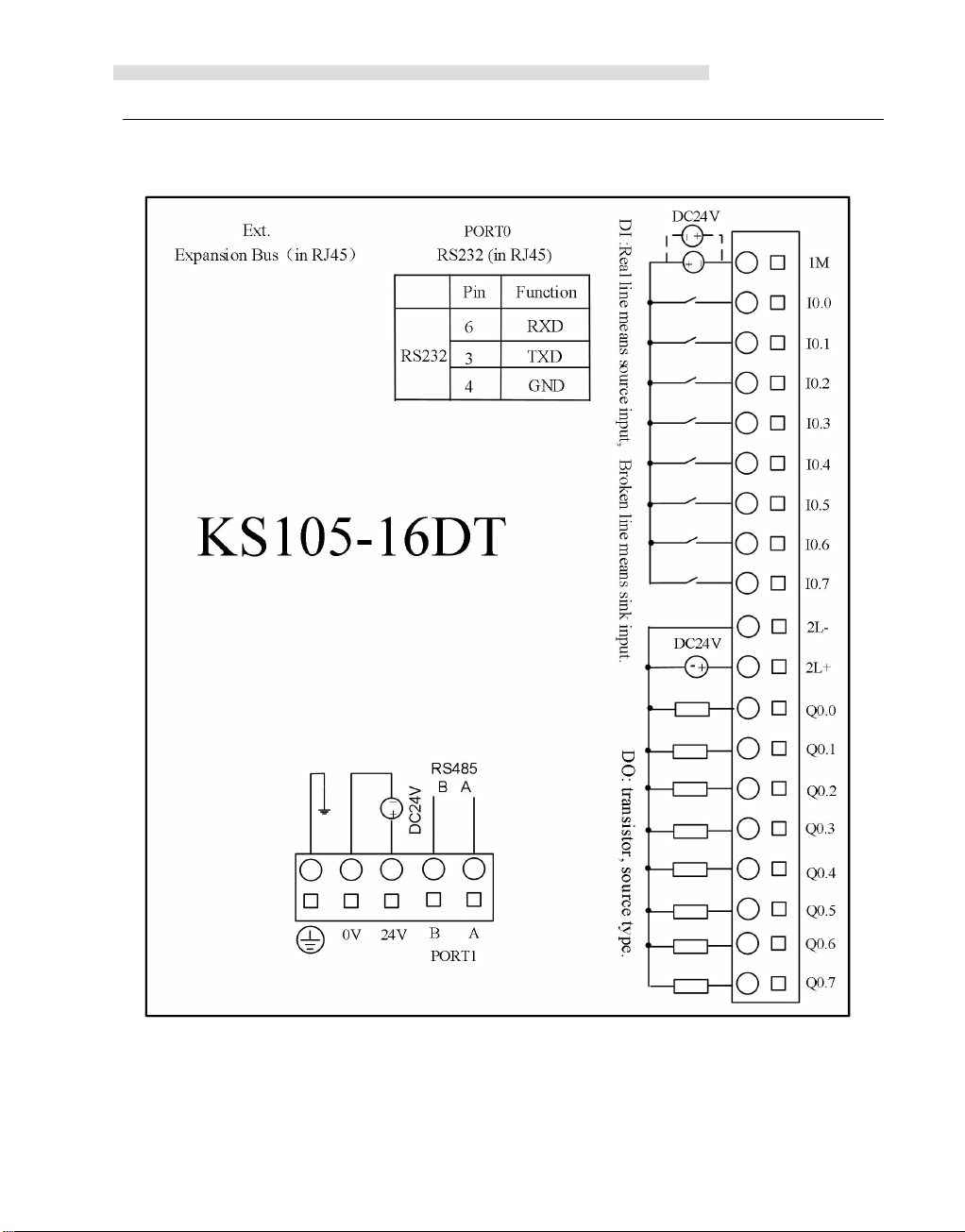
KS105-16DT
DC 24V, DI 8*DC24V,DO 8*DC24V.
1* RS232(programming port),1*RS485.
Expandable(max 14 modules)
KS105C1-16DT
DC 24V, DI 8*DC24V,DO 8*DC24V
1* RS232(programming port),1*RS485,1*CAN
KS105C2-16DT
DC 24V, DI 8*DC24V,DO 8*DC24V
1* RS232(programming port),1*RS485,2*CAN
Expandable(max 14 modules)
Expansion modules
PM122
KS122-12XR
DC24V,DO 12*relay,Modbus slave
PM123
KS123-14DR
DC24V,DI 8*DC24V,DO 6*relay,Modbus slave
PM133
KS133-06IV
DC24V,4 analog input/2 analog output
4-20mA/1-5V/0-20mA/0-10V as option,Modbus slave
Chapter 1 General Introduction
1.1 Summary
Kinco KS series PLC is a small and integrated PLC .It is Kinco new thin and high
performance PLC.
Based on high performance, high reliability and powerful functions of K5/K2, KS series use
higher level CPU. KS has CANopen port, higher speed input and output, small size for
installation.
It can meet more user’s requirement.
1.2 Product List

Kinco-KS series
4
Transport and storage
Ambient
conditions
temperature
-40 --- +70 °C
relative
humidity
10%~95%, no condensation
Altitude
Up to 3000 m
Mechanical
conditions
Free falls
With manufacturer's original packaging, 5 falls from 1m
of height.
Normal Operation
Ambient
conditions
air
temperature
Open equipment : -10 --- +55°C; Enclosed equipment: -10
--- +40°C
relative
humidity
10%~95%, no condensation
Altitude
Up to 2000 m
Pollution
degree
for use in pollution degree 2.
Mechanical
conditions
Sinusoidal
vibrations
5<f<8.4Hz, Occasional: 3.5mm amplitude; Continuous:
1.75mm mplitude.
8.4<f<150, Occasional: 1.0g acceleration; Continuous:
0.5g acceleration.
Shock
occasional excursions to 15g, 11 ms, half-sine, in each of 3
mutually perpendicular axes.
Electromagnet
ic
Electrostatic
discharge
±4kV Contact, ±8kV Air. Performance criteria B.
1.3 Environmental Condition
Kinco-KS accords with GB/T 15969.3-2007(idt IEC61131-2:2007)standard and test
specifications.
The following table lists the conditions and requirements for Kinco-KS to work properly. It
is the user's responsibility to ensure that the service conditions are not exceeded.

Kinco-KS series
5
compatibility
(EMC)
High energy
surge
a.c. main power: 2KV CM, 1KV DM;
d.c. main power: 0.5KV CM, 0.5KV DM;
I/Os and Communication port: 1KVCM.
Performance criteria B.
Fast transient
bursts
main power: 2KV,
5KHz.
I/Os and Communication port:
1KV,
5KHz.
Performance criteria B.
Voltage drops
and
interruptions
a.c. supply: at 50Hz, 0% voltage for 1 period; 40% voltage
for 10 periods; 75% voltage for 20 periods.
Performance criteria A.
Ingress Protection Rating
IP20

6
Chapter 2 CPU Module Introduction
2.1 Overview
2.1.1 Structure
Kinco-KS series
2.1.2 CPU Types
Kinco-KS provides different CPU models with a diversity of features and capabilities, all the
CPU use DC24V power supply. The following table describes main technical data of each
CPU model.

Kinco-KS series
7
Parameters
KS105-16DT
KS105C1-16DT
KS105C2-16DT
Power supply
Rated voltage
DC24V
Voltage range
DC20.4V-28.8V
I/O
Digital
8*DI / 8*DO
Analog
--
Expansion14---
14
CAN
---
CANopen master、
slave and free protocol
CAN1 can support CANopen
slave and free protocol
CAN2 can support CANopen
master and free protocol.
Serial port
PORT0,RS232,support programming protocol, MODBUS RTU slave, free protocol
PORT1,RS485,support programming protocol, MODBUS RTU (as a master or
slave), free protocol
High speed
counter
4, Max 200KHz,support single and double
High speed
output
4
Channel 0&1&2 Max 200KHz (load resistance is less than 1.5KΩ at highest
frequency)。
Channel 3 Max 10KHz
Interrupt
4,I0.0-I0.3 interrupt up and down
Storage
Programming
Max 4K bytes instruction
Data
M area 1K bytes;V area 4K bytes

8
Data backup
E2PROM,448 bytes
Data retention
2K bytes. Lithium battery ,3 years at normal environment
Other
Timer
256
1ms :4
10ms :16
100ms :236
Timer
interruption
2,0.1ms
Counter
256
RTC
yes,the difference is 5 min/month at 25℃
2.2 Functions
Change CPU status
Kinco-KS series
2.2.1 CPU Status and LEDs
The CPU has two modes: STOP mode and RUN mode.
In RUN mode, the CPU executes the main scan cycle and all interrupt tasks.
In STOP mode, the CPU will set all output channels (including DO and AO) to the known
values which are specified in the [Hardware Configuration] through Kincobuilder, and only
process communication requests which comes from KincoBuilder software and other
Modbus RTU master device.
Kinco KS provides two ways for manually changing the CPU status: Using the operation
switch (RUN/STOP); Executing [Debug] -> [RUN] or [STOP] menu command in
Kincobuilder.
Usually when the PLC is power on, the PLC status is based on switch and Kincobuilder

Kinco-KS series
9
(1) The PLC status only depend on Kincobuilder RUN/STOP setup. The switch won’t be
a— PLC RUN mistake (strong mistake) will stop the PLC
b— The user use Kincobuilder [setup], PLC is RUN/STOP status
c— Users use STOP instruction to stop PLC
d— If downloading project failed, PLC will keep STOP status. Until below situation
CPU Status LED
[RUN] or [STOP]. If switch and Kincobuilder are RUN, the PLC real status is RUN. The
PLC real status is STOP for all other situation.
In below situation, the PLC status depend on single control way.
valid.
happen.
(2)PLC status only depend on switch, Kincobuilder RUN/STOP won’t be valid.
a—PLC is power on again. PLC status depend on the switch
b—Kincobuild execute clean PLC instruction. After cleaning PLC status depend on
switch.
c—When downloading, if switch is RUN, then PLC will be defaulted STOP for
downloading.
After downloading, PLC will be RUN again. If switch is STOP,PLC will be STOP after
downloading.
d—Anytime switch can change PLC RUN/STOP status
The CPU module provides 4 status LEDs: RUN, STOP, Comm. and Err.
Run, Err LEDs show the CPU operation status.
【Run】:If CPU is in RUN status,it will turn on. If CPU is in STOP status,it will turn
off.
【Err.】:If CPU detects error in user program or module, it will turn on.
KS separates errors into three levels: Fatal error, Serious error, Normal error. When CPU
detects an error, it will use different way to handle according to error level and turn on Err
LED, then it will save the error code in sequence for user analysis.

Kinco-KS series
10
2.2.2 Programming port and serial port
KS provides 2 communication ports,PORT0 and PORT1.It supports baud rate up to
115.2kbps.PORT0 can be used as programming port and also supports Modbus RTU slave
protocol and free protocol.PORT1can be used as programming port and also supports Modbus
RTU protocol (as a slave or master) and free protocol.
RS232 programming port is in the RJ45 port. Pins and functions as below,
RS232 can’t insert and release with power. So we should turn off power of CPU or PC,
otherwise it will break ports.
2.2.3 CAN port
KS105C1-16DT has 1 CAN port, CAN.It can support CANopen master、slave and free
protocol.

Kinco-KS series
11
KS105C2-16DT has 2 CAN ports, CAN1 and CAN2. CAN2 can support CANopen master
and free protocol.CAN1 can support CANopen slave and free protocol.
2.2.4 Expansion modules
KS105-16DT has expansion port, it can connect KS series expansion modules
CAN1 port of KS105C2-16DT can work as expansion port, also it support protocol.
Users can use them directly without setup, PLC can identify it automatically.( only one
between expansion or CANopen communication)
CPU can connect expansion modules with standard double wires directly. Expansion modules
have one input port and one output port. It is convenient to connect multiple expansion
modules.
Pls reference below figure.
We don’t need to setup address for connecting expansion modules. The real address in the net
depend on the turn that KincoBuilder configurate hardware.

Kinco-KS series
12
2.2.5 High Speed Counter and High Speed Pulse Output
KS provides 4 high speed counters (HSC0~HSC3).High speed counter supports multiple
modes: single phase, CW/CCW(Up/Down),AB phase (1 multiplication and 4
multiplication).All can support up to 200KHz(Include single phase and AB phase).
KS provides 4 high speed pulse outputs(Q0.0,Q0.1 and Q0.4, Q0.5).All support PTO and
PWM.Q0.0 and Q0.1 ,Q0.4support up to 200KHz (The resistor of load should be less than
1.5KΩ),Q0.5 supports up to 10KHz.
2.2.6 Edge Interrupts
I0.0-I0.3 in CPU support edge interrupt function, it can execute interrupt by rising edge and
falling edge of input signal. By using this function, it can capture the rising edge and falling
edge of input signal quickly. For some input signal whose pulse width is less than the CPU
scan time, it can respond quickly.
2.2.7 Data Retentive and Data Backup
Data retentive means the data in RAM can retain after power failure.CPU provides a lithium
battery (Replaceable but un-rechargeable) for data retentive.When CPU loses power, the data in
the RAM will be maintained by the lithium battery, and the retentive ranges will be left
unchanged at next power on. Through [Hardware] configuration in KincoBuilder, user can
select the type of data retentive (Such as V,C area) and the range. The life of battery is 5 years
and the retaining duration is 3 years at normal temperature.
Data backup is that CPU provides an E2PROM to store data permanently. At power on, the
CPU will restore the data from E2PROM into RAM to execute.
Note: Because E2PROM has a writing limit of 1 million times, users should avoid to write data
into data backup area frequently.
There are 448 bytes in V area for data backup (VB3648--VB4095),the data in this area will

Kinco-KS series
13
The lithium battery is CR2032(3V) with connector. As shown in
figure,
user can order the battery separately.
save in E2PROM automatically.K2 sets VB3648--VB3902 as data backup by default,if user
needs to use VB3903--VB4095 for data backup,it needs to configure in 【PLC hardware
configuration】.The configuration interface is as following figure.
2.2.8 Real-time Clock (RTC)
The real-time clock built in the all CPU modules can provide real-time clock/calendar
indication. Users need to use KincoBuilder【PLC】->【Time of Day Clock...】to set the clock
when using RTC first time. Then users can use real-time clock instructions(READ_RTC、
SET_RTC、RTC_W、RTC_R).
After CPU power off, the real-time clock can be maintained by lithium battery. The life of
battery is 5 years and the retaining duration is 3 years at normal temperature.
2.2.9 Backup Battery
KS can use certain specification lithium battery as backup battery. When PLC is
power-off, it will use the backup battery to maintain real-time clock and RAM.
The backup battery is removable, user can replace new battery by themselves when the
battery is empty.
14
2.3 Wiring diagram
Kinco-KS series

Kinco-KS series
15

Kinco-KS series
16

17
2.4 Dimension
DI Specifications
Input type
Source/Sink
Kinco-KS series
2.5 Technical Specification

Kinco-KS series
18
Rated input voltage
DC 24V (Max. 30V)
Rated input current
3.5mA@24VDC
Max input voltage of logic 0
5V@0.7mA
Minimum input voltage of logic 1
Common channel:11V@2.0mA
Input filter time delay
· off-to-on
· on-to-off
1.2μs
0.5μs;
Isolation between input and internal
circuit
· Mode
· Voltage
Opto-electrical isolation
500VAC/1 min
DO Specifications(Transistor type)
Output type
Source
Rated power supply voltage
DC24V,allowance range:
DC20.4V—DC28.8V.(Same as power supply)
Output current per channel
Rated current:200mA,max.300mA @24VDC
Instant impulse current per channel
1A,less than 1s
Output leakage current
Max.0.5цA
Output impedance
Max. 0.2Ω
Output delay
· off-to-on
· on-to-off
Common channel: 12μs; HSC channel: 0.5μs;
Common channel: 35μs; HSC channel: 1μs;
Protection:
·Reverse polarity protection of power
supply
·Inductive load protection
·Short-circuit protection
·Reverse polarity protection of output
No
Yes
Yes
Yes, less than 10s.
Isolation between output and internal
circuit
· Mode
Opto-electrical isolation
500VAC/1 min

Kinco-KS series
19
· Voltage
Type
Mold
MODBUS coder
Area
MODBUS
Address
KS122-12XR
DO(0XXXX)
01,05,15
Q0.0-Q1.3
0-11
KS123-14DR
DI(1XXXX)
02
I0.0 --- I0.7
0-7
DO(0XXXX)
01,05,15
Q0.0-Q0.5
0-5
KS133-06IV
AI(3XXXX)
04
AIW0 --- AIW6
0-3
AO(4XXXX)
03,06,16
AQW0 --- AQWQ
0-1
Chapter 3 Expansion modules
3.1 Introduction
KS series can expand with expansion modules. The power supply for KS expansion modules
is 24VDC. So we don’t need power supply from expansion CANopen.
KS expansion modules have one standard RS485 port. It can work as Modbus slave.
Note: Some address of Modbus RTU master start from 1,so the data in the below form should
add 1 directly.
3.2 DO,DO 12×Relay
Type:Kinco-KS122-12XR.
This modules is DO 12*Relay.

20
3.2.1 Wiring
Kinco-KS series
3.3 DI/O
Type:Kinco-KS123-14DR.
This module is 14IO,DI 8*DC24V,DO 6*Relay.
DI 8×DC24V DO 6×Relay
,

21
3.3.1 Wiring
Kinco-KS series

22
3.3.2 Technic specification
Rated voltage
DC 24V,≥100mA
Electric parameters
input
8(8 channel/group)
Input type
source/drain
Rated voltage
DC 24V
Rated input current
3.5mA@24VDC
Digital “0”max. input voltage
5V
Digital“1”min. input voltage
11V@2.0mA
Isolation between input and inside power
·isolation type
·isolation voltage
Photoelectric couple
500VAC/1 分钟
Output
6 relay(3channel/group)
Max. loading voltage
DC 30V/AC250V
Loading current
2A(DC 30V/AC250V)
Max. output current
10A
Delay time for output on
10ms(max.)
Delay time for output off
5ms(max.)
Life of relay
·Mechanic life(no loading)
· Electric life(rated loading)
20,000,000 times(1200times/min)
100,000times(6times/min)
Output isolation
· isolation mode
· isolation voltage
relay
2000Vrms
Measurement and weight
Measurement(length ×width× height)
100×84.5×25.4mm
Net weight
200g
Kinco-KS series

Kinco-KS series
23
3.4 AI/O,AI 4×IV AO 2×IV,current/voltage input/output
type:Kinco-KS133-06IV.
This module have 4*AI and 2*AO. Measure and output standard voltage and current
signal (4-20mA、1-5V、0-20mA、0-10V. All channel in one module can choose different
signal.
3.4.1 Wiring

Kinco-KS series
24
Signal type
Range
Format
4-20mA
3.92-20.4mA
I×1000
0-20mA
0-20.4mA
1-5V
0.96-5.1V
V×1000
0-10V
0-10.2V
Signal types
Output range
Ourput value
4-20mA
3.92-20.4mA
I×1000
0-20mA
0-20.4mA
1-5V
0.96-5.1V
V×1000
0-10V
0-10.2V
3.4.2 measure range and measure value for AI
The input signal in each channel will sample ADC and counter. The results will be send
to CPU AI area from expansion CAN. Then user programming can visit it.
All the signal types have detection range. If the value is over range, the modules will
warn, and the LED will be on. Meanwhile it will send problem file to CPU by expansion
module. Pls connect all the channels that is not used, also setup signal type to 【0-20mA】 or
【0-10V】,then these channels won’t warn.
Below is detection range and value format. I is input current, V is input voltage.
3.4.3 AO output range and value format
AQ output will be send AO modules by expansion bus, then counter and change. After that it
will output from channel by DAC.
The output range of all signal types is limited. If the output is over range, the output will keep
the up/down limited value.
Below form is output range and value format., I is real current, V is real voltage

25
3.4.4 Technical specification
Electric parameters
AI channels
4
Rated supply current
DC 24V,≥100mA
Signal type
4-20mA、1-5V、0-20mA、0-10V
Resolution
12 bit
Accuracy
0.3% F.S.
Signal limitation
Current is not over 24mA , voltage is not over
12V
Change speed(each channel)
15 times /S
Input resistor
Current mode:<=250Ω
Voltage mode:>4MΩ
AO channel
2
Rated supply current
DC 24V ≥100mA
Signal type
4-20mA、1-5V、0-20mA、0-10V
Resolution
12
Output accuracy
0.3% F.S.
Change speed(each channel)
15times /S
Extra loading
Current mode: Max. 500Ω
Voltage mode: Min. 10KΩ
Dimension and weight
Dimension(length×width× height)
100×84.5×25.4mm
Net weight
200g
Kinco-KS series

Kinco-KS series
26
HSC 0
Mod
e
Description
I0.1
I0.0
I0.5
0
Single-phase up/down counter
with internal direction control:
SM37.3
Clock
1
Reset
2
Reset
Start
3
Single-phase up/down counter
with external direction control
Clock
Direction
4
Reset
Direction
6
Two-phase counter with up/down
clock inputs
Clock Down
Clock Up
Chapter 4 Software Introduction
4.1 Overview
Based on K5, KS use same Kincobuilder software and instructions. Users can reference
K5/K2 manual for most functions. The main difference is the new functions.
4.2 High speed counter
KS provides 4 high speed counters HSC0-HSC3.All can support up to 200KHz
High speed counter supports multiple modes: single phase, CW/CCW,AB phase (1
multiplication and 4 multiplication).
All high speed counter can support maximum 32 PV and support 32 “CV=PV” interrupts. PV
can be set as relative value or absolute value. If it is relative value,
4.2.1 Operation Modes and Inputs of the High-speed Counters
Input signals of high-speed counter include: clock (input impulse), direction, start and reset.
In different operation modes input signals is different. Please see below:

Kinco-KS series
27
9
A/B phase quadrature counter
Clock A
Clock B
HSC1
Mode
Description
I0.4
I0.6
I0.3
I0.2
0
Single-phase up/down counter
with internal direction control:
SM47.3
Clock
1
Reset
2
Reset
Start
3
Single-phase up/down counter
with external direction control
Clock
Direction
4
Reset
Direction
6
Two-phase counter
with up/down clock inputs
Clock
Down
Clock Up
7
Reset
9
A/B phase quadrature counter
Clock A
Clock B
10
Reset
HSC 2
Mode
Description
I0.4
I0.5
0
Single-phase up/down counter
with internal direction control:SM57.3
Clock
9
A/B phase quadrature counter
Clock A
Clock B
HSC 3
Mode
Description
I0.6
I0.7
0
Single-phase up/down counter
with internal direction control:SM127.3
Clock
9
A/B phase quadrature counter
Clock A
Clock B
Control Byte
4.2.2 Control Byte and Status Byte
In SM area,each high-speed counter is assigned control byte to save its configuration
data: one control word (8 bit), current value and pre-set (double-integer with 32 bit). Initial
value of current assigned value. If the current value is written in the high-speed counter, it
will start counting from that value. Please see below:

Kinco-KS series
28
HSC0
HSC1
HSC2
HSC3
Description
SM37.0
SM47.0
SM57.0
SM127.0
Effective electrical level of reset signal :
0=high;1=low
SM37.1
SM47.1
SM57.1
SM127.1
Effective electrical level to start signal:0=high;
1=low
SM37.2
SM47.2
SM57.2
SM127.2
Orthogonal counter rate:0=1x rate;1=4x rate
*
SM37.3
SM47.3
SM57.3
SM127.3
Counting direction:0=Decrease;1=Increase
SM37.4
SM47.4
SM57.4
SM127.4
Write counting direction in HSC? 0= NO; 1=
Yes
SM37.5
SM47.5
SM57.5
SM127.5
Write new pre-set value in HSC? 0= NO; 1=
Yes
SM37.6
SM47.6
SM57.6
SM127.6
Write new current value in HSC? 0= NO; 1=
Yes
SM37.7
SM47.7
SM57.7
SM127.7
Allow this high-speed counter? 0=NO; 1= YES
HSC0
HSC1
HSC2
HSC3
Description
SMD38
SMD48
SMD58
SMD128
Current value
SMD42
SMD52
SMD62
SMD132
Pre-set value
HSC0
HSC1
HSC2
HSC3
Description
SM141.0
SM151.0
SM161.0
SM171.0
Use multiple preset value:0=No. 1=Yes.
SM141.1
SM151.1
SM161.1
SM171.1
Preset value type:0=Absolute value.
1=Relative value.
SM141.2
SM151.2
SM161.2
SM171.2
Preset value comparison interrupt
(“CV=PV”) cyclic execution.
0=No. 1=Yes.
Note:Only valid when preset value is
relative value.
SM141.3
SM151.3
SM161.3
SM171.3
Reserved
SM141.4
SM151.4
SM161.4
SM171.4
Update multiple PV segment and preset
value:0=No. 1=Yes
SM141.5
SM151.5
SM161.5
SM171.5
Reset interrupt variable:0=Yes. 1=No.
SM141.6
SM151.6
SM161.6
SM171.6
Reserved
SM141.7
SM151.7
SM161.7
SM171.7
Reserved
HSC0
HSC1
HSC2
HSC2
Description

Kinco-KS series
29
SMW142
SMW152
SMW162
SMW172
Starting value of preset value table ( It is
offset corresponding to VB0),it must be odd
value.
Status Byte
HSC0
HSC1
HSC2
HSC3
Description
SM36.0
SM46.0
SM56.0
SM126.0
Reserved
SM36.1
SM46.1
SM56.1
SM126.1
Reserved
SM36.2
SM46.2
SM56.2
SM126.2
Reserved
SM36.3
SM46.3
SM56.3
SM126.3
Fault in multiple PV value
table:0=No,1=Yes
SM36.4
SM46.4
SM56.4
SM126.4
Reserved
SM36.5
SM46.5
SM56.5
SM126.5
Current counting direction:
0 = Down; 1= Up
SM36.6
SM46.6
SM56.6
SM126.6
Current value equal to preset value:
0 = No,1 = Yes
SM36.7
SM46.7
SM56.7
SM126.7
Current value greater than preset value:
0 = No,1 = Yes
HSC0
HSC1
HSC2
HSC3
Description
SMB140
SMB150
SMB160
SMB170
Current PV segment No.(Start from 0)
It needs to pay attention that not all the control bits of the control byte is suitable for all
operation mode. For example, “Counting direction” and “Write counting direction in HSC”
can be only used in mode 0,1 and 2 (Single-phase up/down counter
with internal direction control),if the operation mode is with external direction control, then
these two bits will be ignored.
The control byte, current value and preset value are 0 by default after power on.
In SM area, each high-speed counter has a status byte, which indicates the current status
of high speed counter.
4.2.3 Preset value (PV value) setting
KS supports up to 32 PV value for each high speed counter, and supports setting PV value as

Kinco-KS series
30
How to select “multiple PV” mode
Multiple PV table
OFFSET
(1)
Data type
Description
0
BYTE
Quantity of PV
1
DINT
First PV
5
DINT
Second PV
…
DINT
…
(1) All the offset value are the offset bytes related to the table.
(2) When it is set as relative value,then the absolute value of PV data must be greater
relative value or absolute value. It supports “CV=PV” interrupt cyclic execution.
Follows take HSC0 as example to describe PV value function and setting.
In the control byte of each high speed counter, there is one control bit for enable multiple
preset value.
In HSC0, this control bit is SM141.0.
If SM141.0 is 0,it will use single PV value, same as K5 PLC.SMD42 is for new PV
value,SM37.5 is to update this new PV value.
If SM141.0 is 1,it will use multiple PV values. In this situation,SM37.5 and SMD42 is invalid.
All the PV values will be in the PV table(SMW142 is for starting address of the
table),SM141.4 defines whether it use the data in PV table or not.If SM141.4 is 1,it means
when HSC starts, it will get the data from PV table. If SM141.4 is 0,when HSC starts,it will
ignore the data in PV table and get the data from last preset value.
If using PV table,all the PV value will get from PV table.
Each HSC provides one control word which is used to set the starting address of PV table.If
using multiple PV,then all PV value will get from PV table.The starting address of PV table is
odd address of V area,such as 301(Means VB301).
The format of PV table is as follows.
than 1,or PLC will consider the segment of multiple PV finish and count the number
of PV according to this(Higher priority than setting quantity of PV).

Kinco-KS series
31
(3) “CV=PV” interrupts must execute in sequence,it means that after the counter reaches
(4) PV must be set reasonably.Here takes relative value as example,if it is positive
Relative value and absolute value
“CV=PV”interrupt cyclic execution
When it is set as absolute value,the difference between two adjacent PV’s absolute
value must be greater than 1,or PLC will consider the segment of multiple PV finish
and count the number of PV according to this(Higher priority than setting quantity of
PV).
the first PV and executes interrupt,then it will compare with the second PV and so
forth.
counting,PV must be greater than 0,otherwise the “CV=PV”interrupt will never
execute.If it is negative counting,PV must be less than 0,otherwise the
“CV=PV”interrupt will also never execute.
In the control byte of each high speed counter, there is one control bit which is used to set PV
as relative value or absolute value.
For HSC0,the control bit is SM141.1.
If SM141.1 is 0,it means PV is absolute value. When counting value is equal to PV,it will
execute “CV=PV” interrupt. For example,if it sets 3 PV values,such as 1000,2000 and
3000,then when counting value reaches 1000,it will execute the first “CV=PV”interrupt.
When the counting value reaches 2000,it will execute the second “CV=PV” interrupt and so
forth.
If SM141.1 is 1,it means PV is relative value.If counter takes current counting value as
reference,when the value it continues to count is equal to PV,it will execute “CV=PV”
interrupt.For example,if it sets 3 PV values,such as 10,1000 and 1000,and the current
counting value is 100 before HSC starts,then when the counting value reaches 110,1110 and
2110,it will execute corresponding“CV=PV” interrupt.
“CV=PV”interrupt cyclic execution is only valid when PV is set as relative value.
If SM141.0 is 0,it means “CV=PV” interrupt only executes once.When all interrupts finish
execution,then it will stop.If it needs to execute again, it must modify the related registers and

Kinco-KS series
32
Current
counting value
Interrupt times
First value
Second value
Third value
100
1st time
110
1110
2110
2110
2nd time
2120
3120
4120
4120
3rd time
4130
5130
6130
…
N time
………
High speed
counter
Interrupt No.
Description
HSC0
64
“CV=PV”interrupt of 1st PV
65
“CV=PV”interrupt of 2nd PV
…
…(Plus 1)
95
“CV=PV”interrupt of 32nd PV
HSC1
96
“CV=PV”interrupt of 1st PV
97
“CV=PV”interrupt of 2nd PV
…
…(Plus 1)
127
“CV=PV”interrupt of 32nd PV
HSC2
128
“CV=PV”interrupt of 1st PV
129
“CV=PV”interrupt of 2nd PV
execute HSC instruction again.
If SM141.0 is 1,it means “CV=PV” interrupt is cyclic execution.When the last PV interrupt
finishes execution,PLC will take the current counting value as reference to calculate new
value for PV interrupt,then it will start to compare the counting value and execute “CV=PV”
interrupt and so forth.This process will execute cyclically.
For example,it sets 3 PV values,such as 10,1000 and 1000.And the current counting value is
100 before HSC starts,then the value for every interrupt is as following table.
4.2.4 “CV=PV” Envent No.
When it uses single PV mode, the HSC will be fully compatible with K5 (Include “CP=PV”
event No.).
When it uses multiple PV mode, the HSC will assign a new event No. for 32 PV, as shown in
following table.

33
…
…(Plus 1)
159
“CV=PV”interrupt of 32nd PV
HSC3
160
“CV=PV”interrupt of 1st PV
161
“CV=PV”interrupt of 2nd PV
…
…(Plus 1)
191
“CV=PV”interrupt of 32nd PV
4.2.5 How to use high speed counter
Method 1:Use instructions for programming
1)Configure the control byte of HSC and define the current value (i.e. starting value) and the
2)Use HDEF instruction to define the counter and its operation mode.
3)(Optional) Use ATCH instruction to define the interrupt routines.
4)Use HSC instruction to start the high-speed counter.
Method 2:Use wizard of HSC
preset value.
Kinco-KS series
In KS PLC, it provides configuration wizard for high speed counter. Users can use the wizard
to configure all high speed counters and don’t need to program. The wizard is as following
figure:
After using wizard to configure HSC, user also can use “Method 1” to modify the parameters
of HSC.

Kinco-KS series
34
1) Select the counter in【HSC】.
2) Check【Enable HSC】, and then continue following configuration.
3) Select counter mode in【Mode】.
4) Select the starting mode in【Start method】.
How to use HSC wizard:
There are two starting method:
“Using HSC instruction”: If selecting this method, then it needs to execute HSC
instruction to start the HSC. Before executing HSC instruction, it doesn’t need to

Kinco-KS series
35
5) If user needs to use multiple PV mode, then check 【Enable multiple PVs】 and continue
6) If user needs to use single PV mode, then check 【Update preset value(PV)】 in ‘Single
7) For other options, please refer to the descriptions to HSC.
Q0.0
Q0.1
Q0.4
Q0.5
Direction output
channel
Q0.2
Q0.3
Q0.6
Q0.7
Direction enable
Control
SM201.3
SM231.3
SM251.3
SM221.3
configure the registers and execute HDEF instruction.
“Run directly at PLC startup”: If selecting this method, then the HSC will start
automatically after PLC power on without executing any instructions.
to configure all PV values and related ‘Value’ and ‘Interrupt subroutine’. If checking
【Update PV and quantity】, then it can adjust the value in【Quantity】to modify the
number of PV.
PV settings’ and modify the PV value and related interrupt subroutine.
4.3 How to use high speed pulse output
Kinco-KS provides 4 channels for high speed pulse output, they are Q0.0,Q0.1 and
Q0.4,Q0.5.All support PT0 and PWM output.
. Q0.0 and Q0.1,0.4 support maximum 200KHz, and Q0.5supports maximum 10KHz.
KS have one direction output channel for every high speed output. KS provide 1 direction
enable control in SM area.
Direction output channel output motor direction control signal, corotation output 0,inversion
output 1.
Direction enable control can forbid or allow direction output channel. It is highest primary.
If it is forbidden, it won’t output direction control signal. The channel will work as common
DO.

Kinco-KS series
36
1) PLS: it is used to output PTO(Single segment or multiple segments) and PWM.
2) Position control: There are 5 instructions, include PREL(Relative positioning),
3) Following instruction PFLO_F: There are parameters such as input
PTO:Pulse Train Output.
PWM:Pulse-Width Modulation.
Descriptions
Name
Usage
Group
Suitable for
LD
PLS
K2
K5
K6
KS
KW
IL
PLS
PLS Q
U
Opera
nds
Input/O
utput
Data Type
Description
4.3.1 High speed pulse output instruction
KS provides 3types of instructions for high speed pulse output.
PABS(Absolute positioning) ,PHOME(Homing), PJOG(Jogging) and PSTOP(Emergency
stop). User can use these instructions to achieve positioning control easily .Note: When
using position control instructions, the frequency of output pulse must be not less
than 80Hz.
frequency(F),electronic gear ratio(NUME、DENOM), pulse number(COUNT) and so on,
these parameters can be used as variable. The frequency of pulse output is equal to F
multiple by electronic gear ratio. When the pulse number reaches the value COUNT, then
it will stop output and set DONE bit. Note: When using following instruction, the
frequency of output pulse must be not less than 30Hz.
4.3.2 How to use PLS instruction
PLS instruction can implement PTO and PWM output function.

Kinco-KS series
37
Q
Input
INT
Constant(0、1 or 2)
LD
IL
4.3.2.1High-speed Pulse Output Function
Notice: Make sure not to use the PTO and PWM functions if Q0.0 ,Q0.1 and Q0.4 ,
PWM
The PLS instruction is used to load the corresponding configurations of the PTO/PWM from
the specified SM registers and then start outputting pulse until it finish outputting pulse. The
pulse output channel is specified by parameter Q, 0 means Q0.0,1 means Q0.1,2 means
Q0.4,3 means Q0.5.
Note: In user program, it only needs to execute PLS instruction once when it is required. It is
suggested to use edge instruction to execute PLS instruction. If executing PLS executing all
the time, then it can’t output normally.
If EN is 1,then PLS is executed.
If CR is 1,then PLS is executed. It won’t influence the value of CR.
The Kinco-KS provides 4 PTO/PWM pulse generators that can be used to output PTO/PWM.
Thereof, one generator is assigned to Q0.0, called PWM0 or PTO0; the second one is
assigned to Q0.1, called PWM1 or PTO1,and the third one is assigned to Q0.4,called PWM2
or PTO2. The forth one is assigned to Q0.5,called PWM3 or PTO3.
The PTO/PWM pulse generators and the DO mapping area share the memory address
Q0.0 ,Q0.1 and Q0.4,Q0.5. When the user program executes the high speed pulse output
instructions, then the PTO/PWM generator controls the output and prohibits the normal use of
this output channel.
Q0.5 are relay-output!

Kinco-KS series
38
PTO
Single segment pulse
Multiple segment pulse
PWM provides a continuous pulse output with a variable duty cycle, and you can control the
cycle time and the pulse width.
The unit of cycle time and pulse width time is microsecond(us) or millisecond(ms). The
maximum value of cycle time is 65535. If the pulse width time is greater than the cycle time
value, the duty cycle is set to be 100% automatically and the output is on continuously. If the
pulse width time is 0, the duty cycle is set to be 0% and the output is off.
PTO provides a square wave (50% duty cycle) output, and you can control the cycle time and
the number of the output pulses. The unit of cycle time is microsecond(us) or
millisecond(ms).The maximum value of cycle time is 65535.The range of pulse number is
2~4,294,967,295.If the specified pulse number is less than 2, then Kinco-KS will set related
error bit and prohibit the output.
PTO function provides single segment of pulse and multiple segment of pulse.
In single segment pulse mode, it only executes pulse train output once after executing
PLS instruction.
In multi-segment pulse mode, CPU automatically reads the configurations of each PTO
segment from a profile table located in V area and executes the related PTO segment.
The length of each segment is 8 bytes, including a cycle time value (16-bit, WORD), a
reserved value (It is not used now,16-bit, INT), and a pulse number value (32-bit,
DWORD).Thereof, all the pulse output frequency are the same in same segment. It uses PLS
instruction to start multiple segment pulse.
In this mode, the starting address of the profile table is stored in SMW168 (corresponding to
PTO0) ,SMW178 (corresponding to PTO1) , SMW218(corresponding to PTO2) and
SMW248(corresponding to PTO3) .Time base is configured by SM67.3 (corresponding to

Kinco-KS series
39
Byte offset
1
Lengt
h
Segment
Description
0
8-bit
The number of segments (1 to 64)
1
16-bit
1
Initial cycle time (2 to 65535 times of the time
base)
3
16-bit
Reserved
5
32-bit
Pulse number(1 to 4,294,967,295)
9
16-bit
2
Initial cycle time (2 to 65535 times of the time
base)
11
16-bit
Reserved
13
32-bit
Pulse number(1 to 4,294,967,295)
…
…
…
4.3.2.2PTO/PWM Register
Q0.0
Q0.1
Q0.4
Q0.5
Description
SM67.0
SM77.0
SM97.0
SM107.0
PTO/PWM
Whether to update the cycle time: 0 =
No; 1 = Yes
SM67.1
SM77.1
SM97.1
SM107.1
PWM
Whether to update pulse width time: :
0=No;1=Yes
PTO0) ,SM77.3 (corresponding to PTO1) , SM97.3 (corresponding to PTO2) and
SM107.3(corresponding to PTO3). The time base can be in either microsecond or millisecond.
All cycle values in the profile table must use same time base, and cannot be modified when the
profile is executing.
The following table describes the format of the profile table.
1 All the offsets in this column are relative to the starting position of the profile table.
Notice: the starting position of the profile table must be an odd address in V area, e.g.
VB3001.
Each PTO/PWM generator is provided with some registers in SM area to store its
configurations, as shown in following table.

Kinco-KS series
40
SM67.2
SM77.2
SM97.2
SM107.2
PTO
Wheter to update the pulse number: :
0=No;1=Yes
SM67.3
SM77.3
SM97.3
SM107.3
PTO/PWM
Time base: 0=1μs;1=1ms
SM67.4
SM77.4
SM97.4
SM107.4
PWM
Update method:
0 = asynchronous update; 1 = synchronous
update
SM67.5
SM77.5
SM97.5
SM107.5
PTO
Operation mode:
0 = single segment; 1 = multiple segment
SM67.6
SM77.6
SM97.6
SM107.6
Function selection: 0= PTO;1=PWM
SM67.7
SM77.7
SM97.7
SM107.7
PTO/P
WM
Enable/disable: 0=disable;1= enable
Q0.0
Q0.1
Q0.4
Description
SMW68
SMW78
SMW98
SMW108
PTO/PWM
Cycle time , Range:2~65535
SMW70
SMW80
SMW100
SMW110
PWM
Pulse width, Range: 0~65535
SMD72
SMD82
SMD102
SMD112
PTO
Pulse number, Range:1~4,294,967,295
SMW168
SMW178
SMW218
SMW248
The starting location of the profile table (byte offset
from V0)For multi-segment PTO operation only
Q0.0
Q0.1
Q0.4
Q0.5
Description
SM66.0
SM76.0
SM96.0
SM106.0
Reserved
SM66.1
SM76.1
SM96.1
SM106.1
Reserved
SM66.2
SM76.2
SM96.2
SM106.2
Reserved
SM66.3
SM76.3
SM96.3
SM106.3
PWM idle: 0=No, 1=Yes
SM66.4
SM76.4
SM96.4
SM106.4
Whether the cycle time or pulse number of PTO
is wrong: 0=No, 1=Yes
Note: Cycle time and pulse number must be
greater than 1.
All the default value for control byte, cycle time and pulse number are 0.The way to modify
configuration of PTO/PWM is that configure related control registers first, if it is PTO
multiple segment pulse, it also needs to configure profile table, and then execute PLS
instruction.
Each PTO/PWM generator also provides a status bytes in SM area, user can get the status
information of PTO/PWM generator from the status bytes, as shown in following table.

Kinco-KS series
41
SM66.5
SM76.5
SM96.5
SM106.5
PTO profile terminated due to user command:
0=No, 1=Yes
SM66.6
SM76.6
SM96.6
SM106.6
Reserved
SM66.7
SM76.7
SM96.7
SM106.7
PTO idle: 0=No, 1=Yes
4.3.2.3 PTO Operations
Execute the PTO (Single-Segment Operation)
1) Set control byte SMB67 according to the desired operation.
Enable the PTO/PWM function
Select PTO operation
Select 1μs as the time base
Allow updating the pulse number and cycling time.
2) Set SMW68 according to desired cycle time.
3) Set SMD72 according to desired pulse number.
4) (Optional) use ATCH to attach the PTO0-complete event (event 28) to an interrupt
5) Execute the PLS instruction to configure PTO0 and start it.
Changing the PTO Cycle Time (Single-Segment Operation)
The PTO idle bit or PWM idle bit indicate the completion of the PTO or PWM output.
The fallowing takes PTO0 as an example to introduce how to configure and operate the
PTO/PWM generator in the user program.
There are two procedures for using PTO: Configure related control registers and initialize
PTO. Execute PLS instruction.
Use SM0.1 (the first scan memory bit) to call a subroutine that contains the initialization
instructions. Since SM0.1 is used, the subroutine shall be executed only once, and this reduces
CPU scan time and provides a better program structure.
For example, SMB67 = B#16#85 indicates:
routine to respond in real time to a PTO0-complete event.

42
Follow these steps to change the PTO cycle time.
1) Set control byte SMB67 according to the desired operation.
Enable the PTO/PWM function
Select PTO operation
Select 1μs as the time base
Allow updating the cycle time value.
2) Set SMW68 according to desired cycle time.
3) Execute the PLS instruction to configure PTO0 and start it, then a new PTO with the
Changing the PTO Pulse Number(Single-Segment Operation)
1) Set control byte SMB67 according to the desired operation.
Enable the PTO/PWM function
Select PTO operation
Select 1μs as the time base
Allow updating the pulse number
2) Set SMD72 according to desired pulse number.
3) Execute the PLS instruction to configure PTO0 and start it, then a new PTO with the
Execute the PTO (Multiple-Segment Operation)
1) Set control byte SMB67 according to the desired operation.
Enable the PTO/PWM function
For example, SMB67 = B#16#81 indicates:
updated cycle time shall be generated.
Follow these steps to change the PTO pulse count:
Kinco-KS series
For example, SMB67 = B#16#84 indicates:
updated pulse number shall be generated.
For example, SMB67 = B#16#A0 indicates:

Kinco-KS series
43
Select PTO operation
Select multi-segment operation
Select 1μs as the time base
2) Set an odd number as the starting position of the profile table into SMW168.
3) Use V area to configure the profile table.
4) (Optional) Use ATCH to attach the PTO0-complete event (event 28) to an interrupt
5) Execute the PLS instruction to configure PTO0 and start it.
4.3.2.4PWM Operations
Execute PWM
1) Set control byte SMB67 according to the desired operation.
Enable the PTO/PWM function
Select PWM operation
Select 1μs as the time base
Allow updating the pulse width value and cycle time value
2) Set SMW68 according to desired cycle time.
3) Set SMW70 according to desired pulse width.
routine to respond in real time to a PTO0-complete event.
Following takes PWM0 as an example to introduce how to configure and operate the
PTO/PWM generator in the user program.
There are two procedures for using PWM: Configure related control registers and initialize
PTO. Execute PLS instruction.
Use SM0.1 (the first scan memory bit) to call a subroutine that contains the initialization
instructions. Since SM0.1 is used, the subroutine shall be executed only once, and this reduces
CPU scan time and provides a better program structure.
For example, SMB67 = B#16#D3 indicates:

44
4) Execute the PLS instruction to configure PWM0 and start it.
Changing the Pulse Width for the PWM Output
The following steps describes how to change PWM output pulse width.
Enable the PTO/PWM function
Select PWM operation
Select 1μs as the time base
Allow updating the pulse width value and cycle time value
2) Set SMW70 according to desired pulse width.
3) Execute the PLS instruction to configure PWM0 and start it.
Control Registers and Status Registers
Q0.0
Q0.1
Q0.4
Q0.5
Description
1) Set control byte SMB67 according to the desired operation.
For example, SMB67 = B#16#D2 indicates:
Kinco-KS series
4.3.3 How to Use Position Control Instructions
4.3.3.1 How to Modify the Current Value of Position Control
Instructions
For the Position Control instructions,KS1 specifies a control byte for each high-speed output
channel to store its configurations. Besides, it assigns a current value register(DINT) to store
the pulse number which has outputted currently (This value will increase when run forward
and decrease when run reverse).The following table describes the control byte and the current
value.

Kinco-KS series
45
SMD212
SMD242
SMD262
SMD226
Read only. Current value (Increase when run
forward, decrease when run reverse).It indicates the
pulse number which has already outputted.
SMD208
SMD238
SDM258
SDM222
Read/Write. New current value. Use to modify the
current value together with specific control bit.
Q0.0
Q0.1
Q0.4
Q0.4
Description
SM201.7
SM231.7
SM251.7
SM221.7
Read/Write. Emergency-Stop bit.
If this bit is 1, no position control instructions can
be executed.
When executing the PSTOP instruction, this bit is
set to 1 automatically, and it must be reset in the
program.。
SM201.6
SM231.6
SM251.6
SM221.6
Read/Write. Reset the current value or not
1 --- Clear the current value.
0 --- Maintain the current value.。
SM201.5
SM231.5
SM251.5
SM221.5
Reserved
SM201.4
SM231.4
SM251.4
SM221.4
Read/Write. Use to modify current value.
1 - Modify current value.
0 - Maintain the current value.
SM201.3
SM231.3
SM251.3
SM221.3
Read/Write. Direction control bit.
1 --- Disable the direction output channel, it will be
used as normal output.
0 --- Enable the direction output channel.
SM201.0
~
SM201.2
SM231.0
~
SM231.2
SM251.0
~
SM251.2
SM221.0
~
SM221.2
Reserved
How to modify current value
Each high speed output channel has one register for current value, they are SMD212,SMD242
and SMD262,SMD226.The outputted pulse number are stored in these registers. Current
value registers are read only, if user needs to modify the current value, it can use following
methods.

Kinco-KS series
46
Method 1
Method 2
Q0.0
Q0.1
Q0.4
Q0.5
Description
SMD208
SMD238
SDM258
SDM222
Read/Write. New current value. Use to
modify the current value together with
specific control bit.
SM201.4
SM231.4
SM251.4
SM221.4
Read/Write. Use to modify current value.
1 - Modify current value.
0 - Maintain the current value.
User reset bit to clear current value.
The reset bits for 4 output channels are SM201.6、SM231.6 、SM251.6 and SM221.6.
When the reset bit is 1, PLC will set the current value as 0.Therefore, t only needs one
scan time for the reset bit to activate. When it needs to use this bit, try to avoid to keep this bit
always 1 and also and also avoid to set this bit while the Position Control instruction (Include
PHOME, PREL, PABS, JOG and PFLO_F) is executing, otherwise the counting value may be
wrong.
Following takes channel 0 as example to describe how to reset current value.
(* Network 0 *)
(*Based on homing signal, when it moves to homing, it requires to clear current value*)
LD %SM0.0
PHOME
0, %M0.0, %M0.1, %M0.2, %VW0, %VW2, %VW4, %VD6, %VW10, %M0.4, %M0.5, %
MB1
(* Network 1 *)
(*After PHOME finishing, it uses finishing bit “DONE” to clear current value*)
LD %M0.4
R_TRIG
ST %SM201.6
Modify current value by using following registers.
Here takes channel 0 as example to describe the method: If SM201.4 is 0,then it will maintain
the current value SMD212. If SM201.4 is 1, then it will move the value of SMD208 to

Kinco-KS series
47
SMD212.When it needs to use this bit, avoid to keep this bit always 1 and also avoid to set
this bit while the Position Control instruction (Include PHOME, PREL, PABS, JOG and
PFLO_F) is executing, otherwise the counting value may be wrong.
Following takes channel 0 as example to describe how to modify current value:
(* Network 0 *)
(*Based on homing signal, hen it moves to homing, t requires to set current value as 100.*)
LD %SM0.0
PHOME
0, %M0.0, %M0.1, %M0.2, %VW0, %VW2, %VW4, %VD6, %VW10, %M0.4, %M0.5, %
MB1
(* Network 1 *)
(*When PHOME instruction finishing, it uses finishing bit DONE to modify current value.*)
LD %M0.4
R_TRIG
MOVE DI#100, %SMD208
ST %SM201.4
4.3.3.2 Can it change maximum output frequency when position
control instruction is executing?
PREL(Relative position)and PABS(Absolute position) will not change maximum output
frequency when it is executing. It will read the parameters minimum frequency, maximum
frequency and acceleration/deceleration time parameters when it starts, and calculates suitable
acceleration/deceleration segments according to the value of these parameters, then it will
start outputting pulse. During pulse outputting, PREL and PABS will not read the parameters
above again, therefore, changing these parameters will not affect the pulse output.
PJOG(Jogging) will read pulse input frequency(MAXF) all the time when it is executing,
and adjust the pulse output frequency according to new setting frequency.

Kinco-KS series
48
PHOME(Homing) will read the maximum frequency (MAXF) all the time when it is
running at maximum frequency but hasn’t found homing signal, and calculate acceleration or
deceleration segment automatically according the new setting frequency, then it will
accelerate or decelerate to new frequency to output pulse.
4.4 How to use CANopen
KS105C1-16DT CPU provide 1 CAN port, CAN. CAN port can support CANopen
master/slave protocol and free protocol. But only one from 3 options.
KS105C2-16DT provide 2 CAN port, CAN1 and CAN2. CAN2 port can support CANopen
master protocol and free protocol. CAN1 port support CANopen slave protocol and free
protocol. If CAN1 port connect expansion modules, CAN communication is not valid. So
only one for CAN1 expansion protocol and CAN communication.
4.4.1 Wiring
KS105C1-16DT CPU provide one CAN port. It connect directly by 2 RJ45 port. Users
can use any one of them. Pls reference figure.
KS105C2-16DT provide 2 CAN port in 2 RJ45 ports.
The switch on PLC can be used for resistor. Pls reference the printed information on
products.
Note,RJ45 port is for expansion modules connections. Pls use direct net wire for
connection of multiple expansion modules.
4.4.2 Programming
1, Usage of CANopn master is same as K5 series. Pls reference K5/K2 manual.

Kinco-KS series
49
2,When using free protocol instruction ( CAN_INIT 、 CAN_WRITE 、 CAN_READ 、
CAN_RX),CH parameters in KS105C1 is 1. 0 is CAN1 and 1 is CAN2 in KS105C2.
3,CAN slave
Pls enable CANopen slave for programming configuration. Setup baud rate and ID.(Real
ID+ switch)
B:CANopen slave protection only support heartbeat files. Pls download EDS from Kinco
website.
The storage area as below,

50
Data
Length
Start address
End address
Attribute
BYTE
32
IB0
IB31
read
INT32AIW0
AIW62
read
BYTE
32
QB0
QB31
read,write
INT32AQW0
AQW62
read,write
BYTE
32
MB0
MB31
read,write
INT
254
VW0
VW506
read,write
DINT
64
VD1016
VD1268
read,write
FLOAT
64
VR2032
VR2284
read,write
BYTE
254
VB508
VB761
read,write
C: Slave accordance to DS301 V4.2 and DS405 V2.0。
Kinco-KS series
D:Slave port provide 32 TPDO and 32 RPDO. PD0 number should be continuance. For
example, TPD01、TPD02、TPD03 are valid. TPDO1、TPDO3、TPDO4 is not valid.
PD0 support all communication parameters, including COB-ID、forbidden time、timer
and all transfer types.
 Loading...