

Page 1

1
Contents
Chapter 1 Product Acceptance & Model Description ............................................................................................. 4
1.1 Product Acceptance .......................................................................................................................... 4
1.1.1 Items for Acceptance (Wires Included) ............................................................................ 4
1.1.2 Nameplate of Servo Driver ............................................................................................... 4
1.1.3 Nameplate of Servo Motor ............................................................................................... 5
1.2 Component Names ........................................................................................................................... 6
1.2.1 Component Names of CD420/CD430/CD620 Servo Driver ............................................. 6
1.2.2 Component Names of Servo Motor .................................................................................. 7
1.3 Model Description of Servo Motors and Drivers ................................................................................ 7
1.3.1 Servo Drivers ................................................................................................................... 7
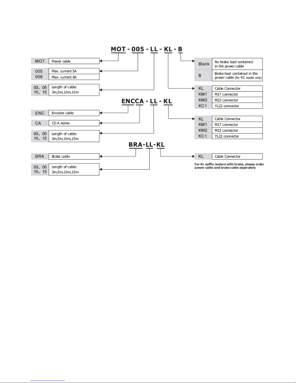
1.3.3 Power,Brake and Encoder cable of Motors ...................................................................... 8
Chapter 2 Precautions and Installation Requirements .......................................................................................... 9
2.1 Precautions ....................................................................................................................................... 9
2.2 Environmental Conditions ................................................................................................................. 9
2.3 Mounting Direction & Spacing ........................................................................................................... 9
2.3.1 Precautions ...................................................................................................................... 9
2.3.2 Servo Driver Installation ................................................................................................. 10
Chapter 3 Interfaces and Wirings of CD Driver ................................................................................................... 12
3.1 Interfaces of CD Driver .................................................................................................................... 12
3.2 External Wirings of CD Driver ......................................................................................................... 14
3.3 X1 Interface of CD Driver ................................................................................................................ 15
3.4 Power Interfaces (CD420/X2, CD430/CD620/X2 and X5) of CD Driver .......................................... 16
3.5 X3/X4 Interfaces of CD Driver ......................................................................................................... 17
3.5.1 X3 Interface.................................................................................................................... 17
3.5.2 X4 Interface.................................................................................................................... 17
Chapter 4 Digital Operation Panel ....................................................................................................................... 18
4.1 Introduction ..................................................................................................................................... 18
4.2 Operation on Digital Operation Panel .............................................................................................. 20
Example 4-1: Set the denominator of electronic gear ratio to 10000 with number system
switching ................................................................................................................................. 20
Example 4-2: Set the speed to 1000 RPM/-1000 RPM with separate regulation of bits ......... 21
Chapter 5 Trial Operation & Parameter Introduction ........................................................................................... 23
5.1 Trial Operation ................................................................................................................................. 23
5.1.1 Objective ........................................................................................................................ 23
5.1.2 Precautions .................................................................................................................... 23
5.1.3 Operating Steps ............................................................................................................. 23
5.1.4 Diagram of Trial Operation ............................................................................................. 24
5.1.1 Diagram of trial operation ........................................................................................................................... 24
5.2 Description of Parameters ............................................................................................................... 25
Parameter List: Group F000 (To Set Driver Instructions) ........................................................ 25
Parameter List: Group F001 (To Set Real-Time Display Data) ............................................... 27
Parameter List: Group F002 (To Set Control Loop Parameters) ............................................. 28
Parameter List: Group F003 (To Set Input/Output & Pattern Operation Parameters) ............. 30
Page 2

2
Parameter List: Group F004 (To Set Motor Parameters) ........................................................ 33
Parameter List: Group F005 (To Set Driver Parameters) ........................................................ 34
Chapter 6 Operation on Input/Output Ports ......................................................................................................... 35
6.1 Digital Input Signals .......................................................................................................... 35
6.1.1 Polarity Control on Digital Input Signals ......................................................................... 35
Example 6-1: Polarity Setting for Digital Input Signal DIN1 ..................................................... 36
6.1.2 Simulation of Digital Input Signals .................................................................................. 36
Example 6-2: Analog-to-Digital Output Port: DIN1 .................................................................. 37
6.1.3 Status Display of Digital Input Signals ........................................................................... 37
Example 6-3: Driver Enable Setting ........................................................................................ 39
Example 6-4: Disabling Position Positive/Negative Limit Settings .......................................... 39
Example 6-5: Operation Mode Control on Drivers .................................................................. 40
6.1.5 Wirings of Digital Input Port............................................................................................ 40
6.2 Digital Output Signals ...................................................................................................................... 41
6.2.1 Polarity Control on Digital Output Signals ...................................................................... 41
6.2.2 Simulation of Digital Output Signals ............................................................................... 41
6.2.3 Status Display of Digital Output Signals ......................................................................... 42
6.2.4 Addresses and Functions of Digital Output Signals ....................................................... 42
Example 6-6: ―Ready‖ settings ................................................................................................ 43
6.2.5 Wiring at the Digital Output Port ..................................................................................... 43
Chapter 7 Mode Operation .................................................................................................................................. 45
7.1 Pulse Control Mode (―-4‖ Mode) ...................................................................................................... 45
7.1.1 Wiring in Pulse Control Mode......................................................................................... 45
7.1.2 Parameters for Pulse Control Mode ............................................................................... 46
7.1.3 Examples of Pulse Control Mode ................................................................................... 49
Example 7-1: Pulse control mode ―-4‖ – enable the driver through external digital input ........ 49
Example 7-2 Pulse control mode ―-4‖ – enable the driver automatically after driver power on 50
7.2 Speed Mode (―-3‖ or ―3‖ Mode) ....................................................................................................... 51
7.2.1 Wiring in Analog – Speed Mode ..................................................................................... 52
7.2.2 Parameters for Analog – Speed Mode ........................................................................... 52
7.2.3 Analog Signal Processing .............................................................................................. 53
7.2.4 Calculation Procedure for Analog – speed Mode ........................................................... 54
7.2.5 Examples of Analog – Speed Mode ............................................................................... 55
Example 7-3: Analog – speed mode (without setting the dead zone voltage and offset voltage)
................................................................................................................................................ 55
Example 7-4 Analog – speed mode (setting the dead zone voltage) ...................................... 57
Example 7-5 Analog – speed mode (setting the offset voltage) .............................................. 59
Example 7-6: Analog – speed mode (setting the dead zone voltage and offset voltage) ........ 60
7.3 Torque Mode (―4‖ Mode) .................................................................................................................. 62
7.3.1 Wiring in Analog – Torque Mode .................................................................................... 62
7.3.2 Parameters for Analog – Torque Mode .......................................................................... 62
7.3.3 Analog Signal Processing .............................................................................................. 63
7.3.4 Calculation Procedure for Analog – Torque Mode .......................................................... 64
7.3.5 Examples of Analog – Torque Mode .............................................................................. 64
Example 7-7: Analog – torque mode (without setting the dead zone voltage and offset voltage)
................................................................................................................................................ 65
Page 3

3
Example 7-8: Analog – torque mode (setting the dead zone voltage and offset voltage) ........ 67
7.4 Internal Multi-position Control Modes (―1‖ Mode) ............................................................................ 68
Example7-9: Internal multi-position control mode ................................................................... 69
7.5 Internal Multi-speed Control Modes (―-3‖ or ―3‖ Mode) .................................................................... 71
Example 7-10: Internal multi-speed control ............................................................................. 72
7.6 Internal Torque Control Mode (―4‖ Mode) ........................................................................................ 73
7.7 Homing Mode (―6‖ Mode) ................................................................................................................ 73
Example 7-11:Using method 7 for homing. .......................................................................... 80
Chapter 8 Control Performance ................................ ................................................................ ........................... 86
8.1 Driver Performance Tuning ............................................................................................................. 86
8.1.1 Manual Adjustment ........................................................................................................ 86
8.1.2 Auto Adjustment (Only for Velocity Loops) ..................................................................... 90
8.2 Oscillation Inhibition ........................................................................................................................ 92
Chapter 9 Communication ................................................................................................................................... 94
Fig. 9-1 Communication cables between a PC and a servo driver ...................................................................... 94
9.1 Transport Protocol ........................................................................................................................... 94
9.2 Data Protocol .................................................................................................................................. 95
9.2.1 Download(from Host to Slave) ....................................................................................... 95
9.2.2 Upload(From Slave to Host) .......................................................................................... 96
Chapter 10 Troubleshooting ................................................................................................................................ 97
10.1 Alarm Messages ............................................................................................................................ 97
10.2 Alarm Causes & Troubleshooting .................................................................................................. 98
Chapter 11 Specification ...................................................................................................................................... 99
11.1 Servo Drivers and Motors Selection Table ..................................................................................... 99
11.2 Servo Driver ................................................................................................................................ 100
11.2.1 Technical Specification Table for Servo Driver............................................................ 100
11.2.2 Mechanical Dimension Diagram for Servo Driver ....................................................... 101
11.3 Dimensions/Torque Curve/Technical Specifications of Servo Motors .......................................... 102
11.3.1 SMH60 Servo Motor ................................................................................................... 102
11.3.2 SMH80 Servo Motor ................................................................................................... 103
11.3.3 SMH110 Servo Motor ................................................................................................. 104
11.4 Wiring Diagram for Servo Motor Cable ........................................................................................ 106
11.4.1 Wiring Diagram for the Power Cable .......................................................................... 106
11.4.2 Wiring Diagram for the Encoder Cable ....................................................................... 107
Chapter Appendix .............................................................................................................................................. 108
Appendix One:Selection Table for Brake Resistor ............................................................................... 108
Appendix Two:Selection Table for Fuse .............................................................................................. 108
Page 4
4
Chapter 1 Product Acceptance & Model
Description
1.1 Product Acceptance
1.1.1 Items for Acceptance (Wires Included)
Table 1-1 Product acceptance
Item for Acceptance
Remark
Whether the model of a delivered CD series
servo system is consistent with the
specified model
Check the nameplate of a servo motor and
that of a servo driver
Whether the accessories included in the
packing list are complete
Check the packing list
Whether any breakage occurs
Check the external appearance completely
for any losses that are caused by
transportation
Whether any screws are loose
Check for loose screws with a screwdriver
Whether the motor wiring is correct
Purchase motor accessory packages if no
wirings are purchased
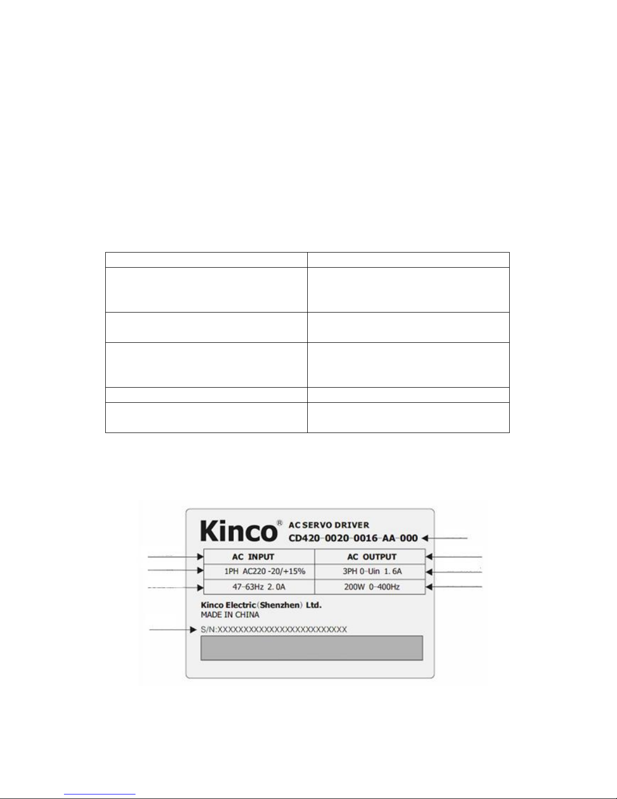
1.1.2 Nameplate of Servo Driver
AC input
Voltage specification
Current specification
Serial No.
Model
AC output
Output
specification
Output power
Bar code
Fig. 1-1 Nameplate of a servo driver
Page 5
5
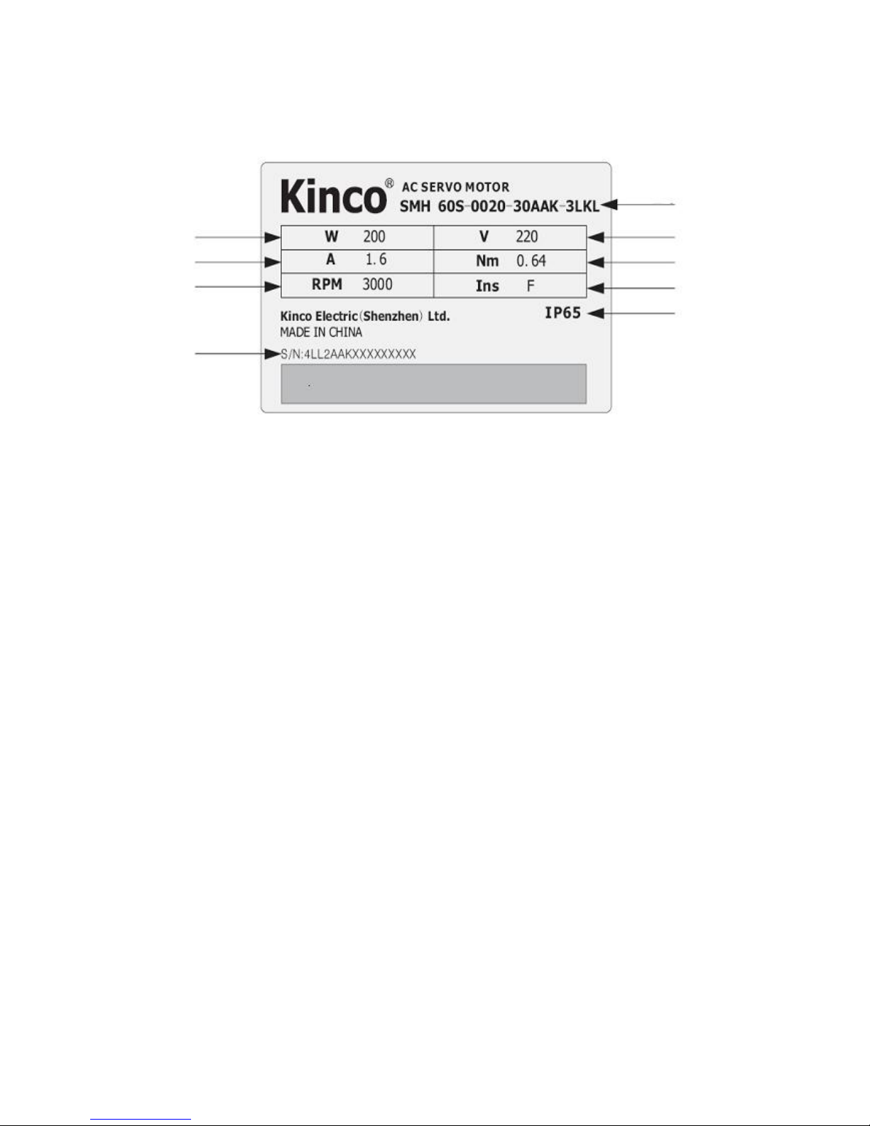
1.1.3 Nameplate of Servo Motor
Rated power
Rated current
Rated rotation speed
Serial No.
Model
Rated voltage
Rated torque
Insulation class
Protection class
Bar code
Fig. 1-2 Nameplate of a servo motor
Page 6
6
1.2 Component Names
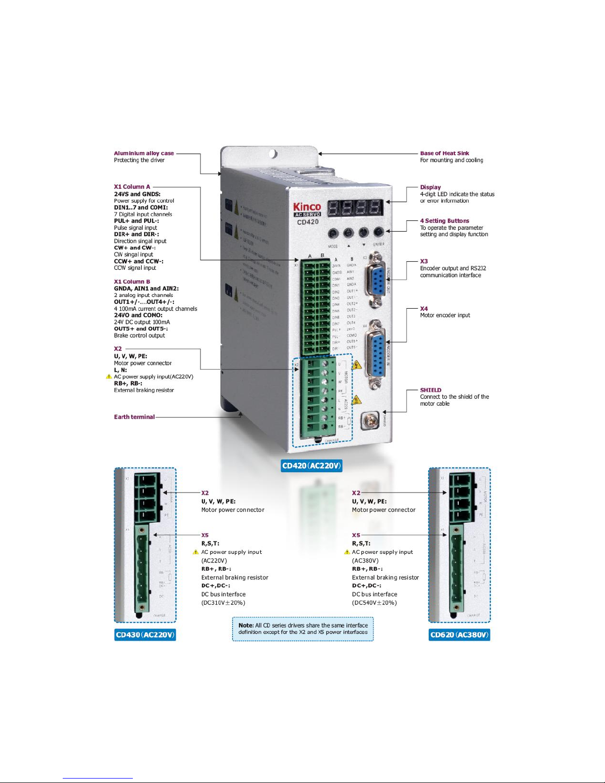
1.2.1 Component Names of CD420/CD430/CD620 Servo Driver
Fig. 1-3 Component Names of CD420/CD430/CD620 Servo Driver
Page 7
7
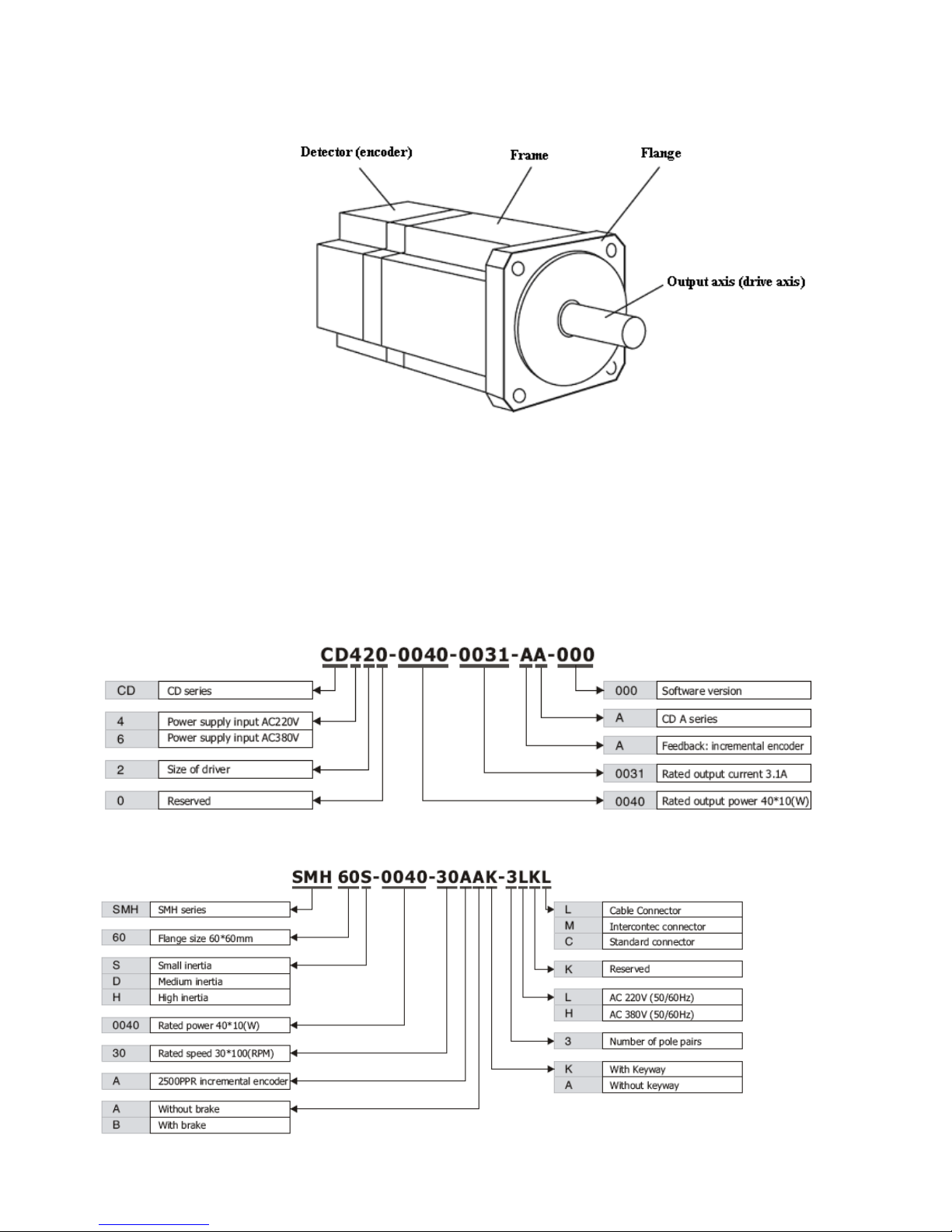
1.2.2 Component Names of Servo Motor
Fig. 1-4 Component names of a servo motor (brakes excluded)
1.3 Model Description of Servo Motors and Drivers
1.3.1 Servo Drivers
1.3.2 Servo Motors
Page 8
8
1.3.3 Power,Brake and Encoder cable of Motors
Page 9
9
Chapter 2 Precautions and Installation
Requirements
A Kinco CD series servo driver is installed on a base. If a driver is not installed properly, some faults may
occur. To avoid this, install the driver by abiding by the following precautions.
2.1 Precautions
1. Tightly fasten the screws that fix the motor;
2. Make sure to tightly fasten all fixed points when fixing the driver;
3. Do not tighten the cables between the driver and the motor/encoder;
4. Use a coupling shaft or expansion sleeve to ensure that both the motor shaft and equipment shaft are
properly centered;
5. Do not mix conductive materials (such as screws and metal filings) or combustible materials (such as oil) into
the servo driver;
6. Avoid the servo driver and servo motor from dropping or striking because they are precision equipment;
7. For safety, do not use any damaged servo driver or any driver with damaged parts.
2.2 Environmental Conditions
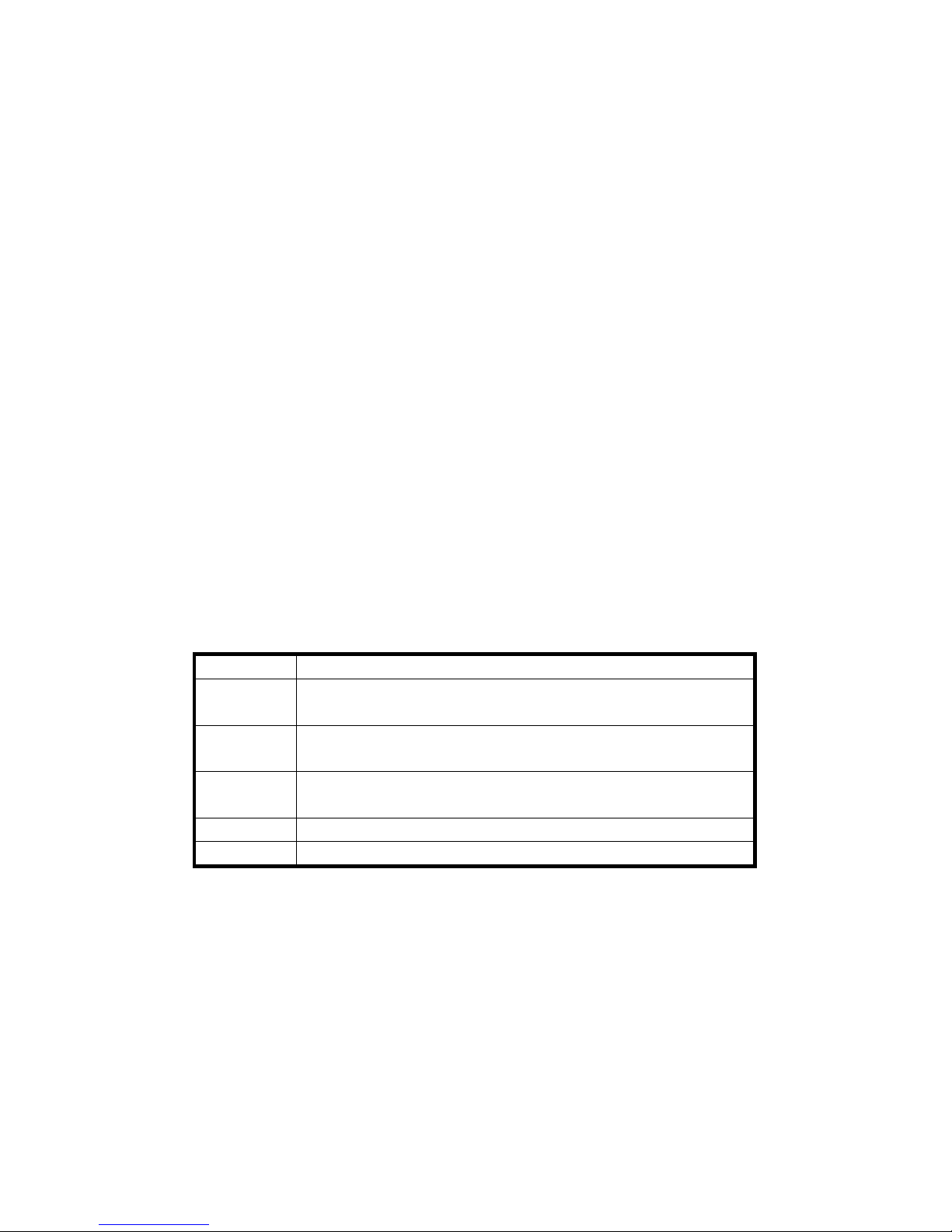
Table 2-1 Environmental conditions
Environment
Condition
Temperature
Operating temperature: 0C - 40C (ice free)
Storage temperature: - 10C - 70C (ice free)
Humidity
Operating humidity: below 90% PH (non-condensing)
Storage humidity: below 90% PH (non-condensing)
Air
Indoor (No direct sunlight), no corrosive gas or combustible gas
No oil vapor or dust
Height
Below 1000 m above the sea level
Vibration
5.9 m/s2
2.3 Mounting Direction & Spacing
2.3.1 Precautions
1. To prevent possible faults, install a servo driver in a proper direction;
2. To prevent possible faults, ensure that the space between a servo driver and the inner wall of the control
cabinet as well as that between the servo driver and the neighboring driver are the same as specified space..
Page 10
10
2.3.2 Servo Driver Installation
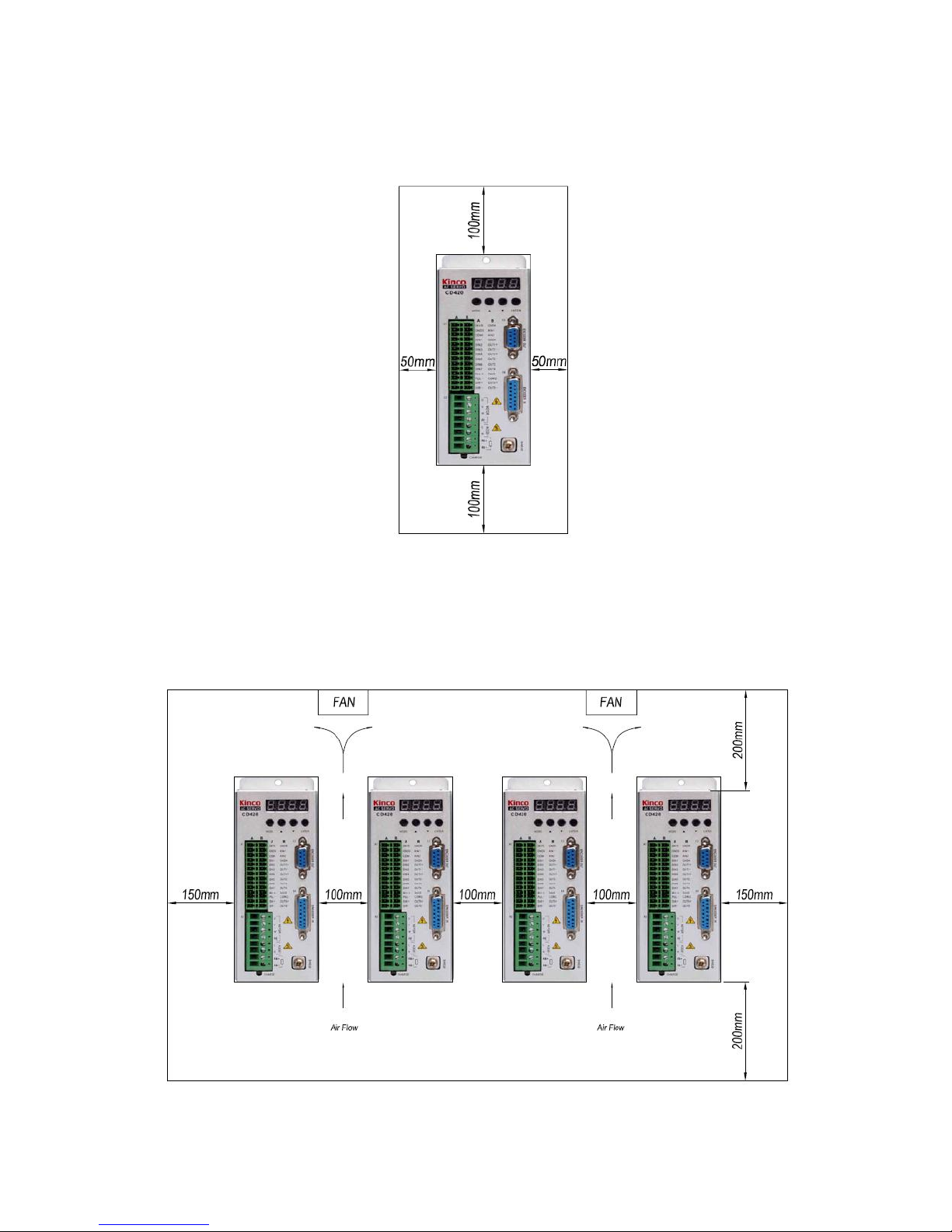
1. Installing a servo driver:
Fig. 2-1 Installing a servo driver
2. Installing multiple servo drivers:
Ensure that there is enough space between a servo driver and the inner wall of a control cabinet. Additionally,
install cooling fans at the upper part of the servo driver. To prevent localized overheating of the environmental
temperature on the servo driver, you need to keep an even temperature in the control cabinet.
Fig. 2-2 Installing multiple servo drivers
3. Other Cases
Page 11
11
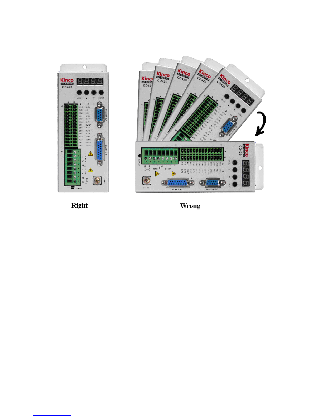
Install the servo driver vertically on a wall.
Take fully into account heat dissipation when using any heating components (such as braking resistors) so
that the servo driver is not affected.
Fig. 2-3 Installation direction
Page 12
12
Chapter 3 Interfaces and Wirings of CD Driver
3.1 Interfaces of CD Driver
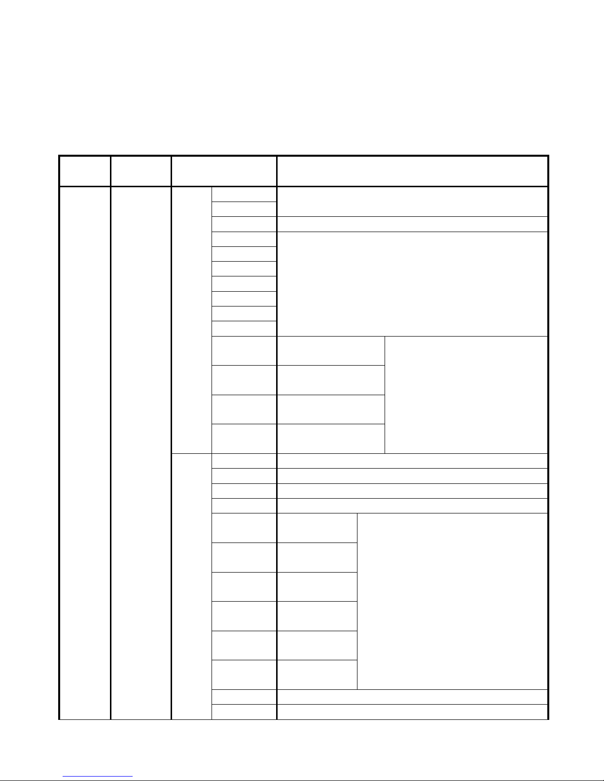
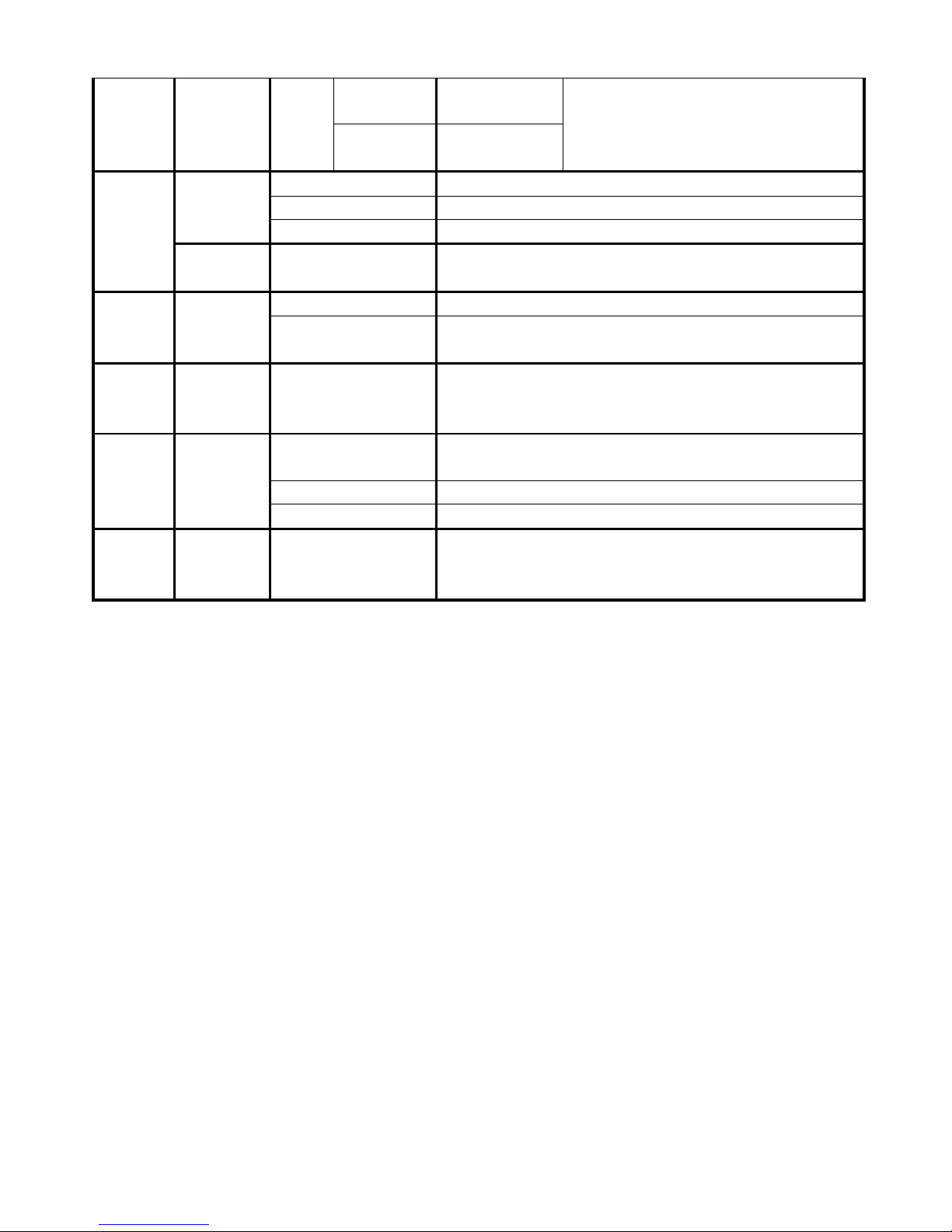
Table 3-1 Interfaces of a CD driver
Interface
Applicable
Driver
Symbol
Function
X1
CD420
CD430
CD620
A
24VS
External logic power (24 V +/- 15%) interface with a minimum
of 0.5 A current output
GNDS
COMI
Common port of digital input signals
DIN1
Digital input interface
Valid signal: 12.5 V ~ 24 V
Invalid signal: less than 5 V
DIN2
DIN3
DIN4
DIN5
DIN6
DIN7
PUL+
Pulse or positive pulse
interface (+)
Input voltage range: 3 V to 5 V
If the input voltage is 24 V, the
interface is cascaded to the 2K
resistance.
PUL-
Pulse or positive pulse
interface (-)
DIR+
Direction or negative
pulse interface (+)
DIR-
Direction or negative
pulse interface (-)
B
GNDA
Analog signal ground
AIN1
Analog signal input interface 1. Input impedance: 200 K
AIN2
Analog signal input interface 2. Input impedance: 200 K
GNDA
Analog signal ground
OUT1+
Digital output
interface 1+
Maximum output current: 100 mA
Withstanding voltage:24V
OUT1-
Digital output
interface 1-
OUT2+
Digital output
interface 2+
OUT2-
Digital output
interface 2-
OUT3
Digital output
interface 3
OUT4
Digital output
interface 4
24VO
Power input port of digital output signals 5
COMO
Common port of digital output signals
Page 13
13
OUT5+
Digital output
interface 5+
Maximum output current: 800 mA
OUT5-
Digital output
interface 5-
X2
CD420
U/V/W/PE
Power cable interface of a motor
L/N
Main power interface (single-phase 220 VAC)
RB+/RB-
Braking resistor interface
CD430
CD620
U/V/W/PE
Power cable interface of a motor
X3
CD420
CD430
CD620
ENCODER OUT
Signal output interface of a motor encoder
RS232
RS232 interface that communicates with a host PC or
controller
X4
CD420
CD430
CD620
ENCODER IN
Encoder interface of a motor
X5
CD430
CD620
R/S/T
Main power interface (single-phase or three-phase AC 220V
for CD430 and three-phase AC 380 V for CD620)
RB+/RB-
Braking resistor interface
DC+/DC-
DC bus interface
-----
CD420
CD430
CD620
SHIELD
Fixed terminal for the shielded wires of motor cables
Page 14
14
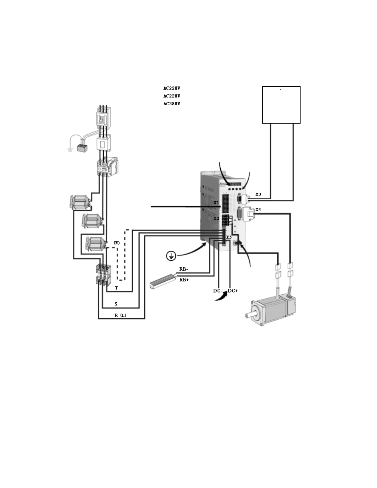
3.2 External Wirings of CD Driver
Power supply
(L) RST (N)
Surge controller
AC reactor
CD420 (single phase)
CD430 (single phase/
three phases)
CD620 (three phases)
Circuit breaker
Noise filter
Electromagnetic contactor
Protective tube
Host computer
Communication control
Encoder output
Numeric display
Numeric display key
Logic power, I/O control
Encoder line
Power line
Shielded wiring terminal
Braking resistor
DC bus
Note: For the CD420/CD430/CD620, all interfaces are the same except for X2 and X5 power
interfaces. For details, see Figure 3-4.
Fig. 3-1 External wirings of a CD driver
Page 15
15
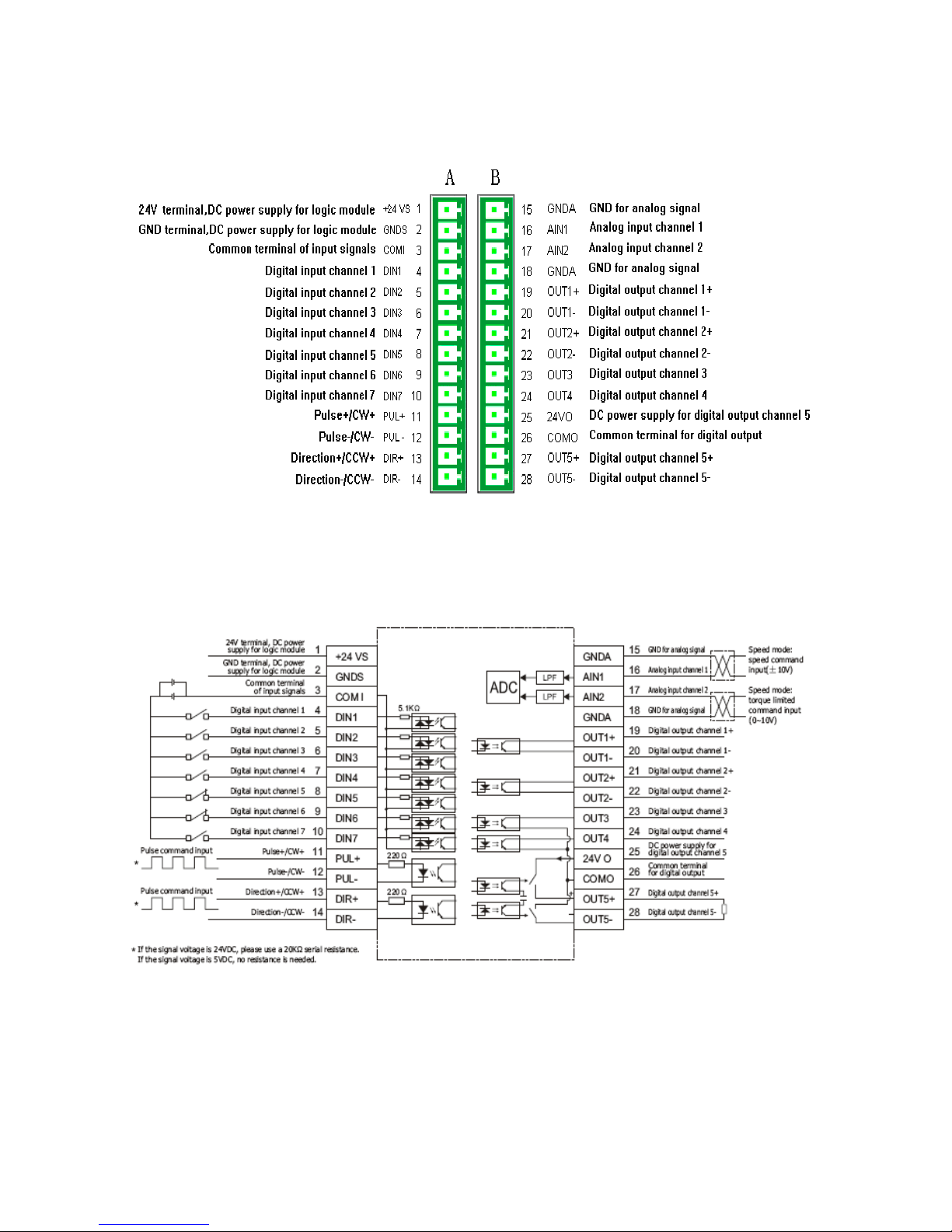
3.3 X1 Interface of CD Driver
Fig. 3-2 X1 interface of a CD driver
Fig. 3-3 Wirings of the X1 interface of a CD driver
Page 16
16
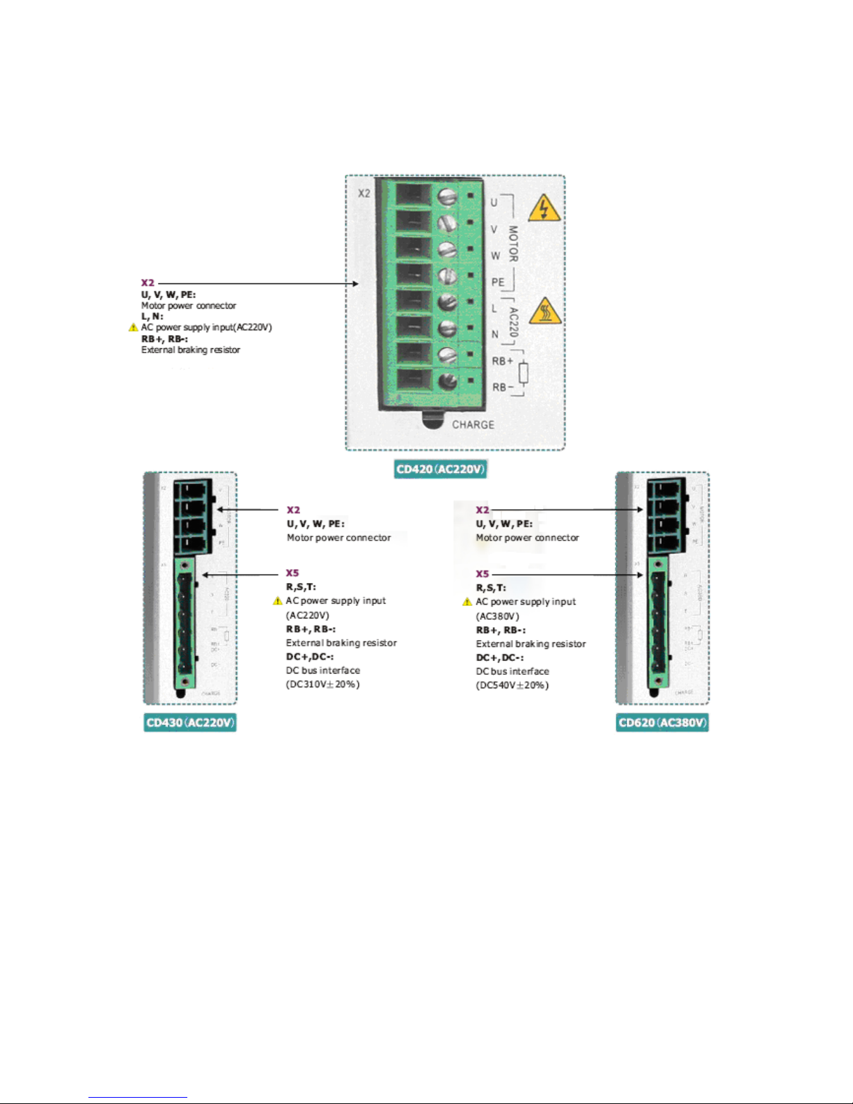
3.4 Power Interfaces (CD420/X2, CD430/CD620/X2 and X5) of CD Driver
Fig. 3-4 Power interfaces of a CD driver
Page 17
17
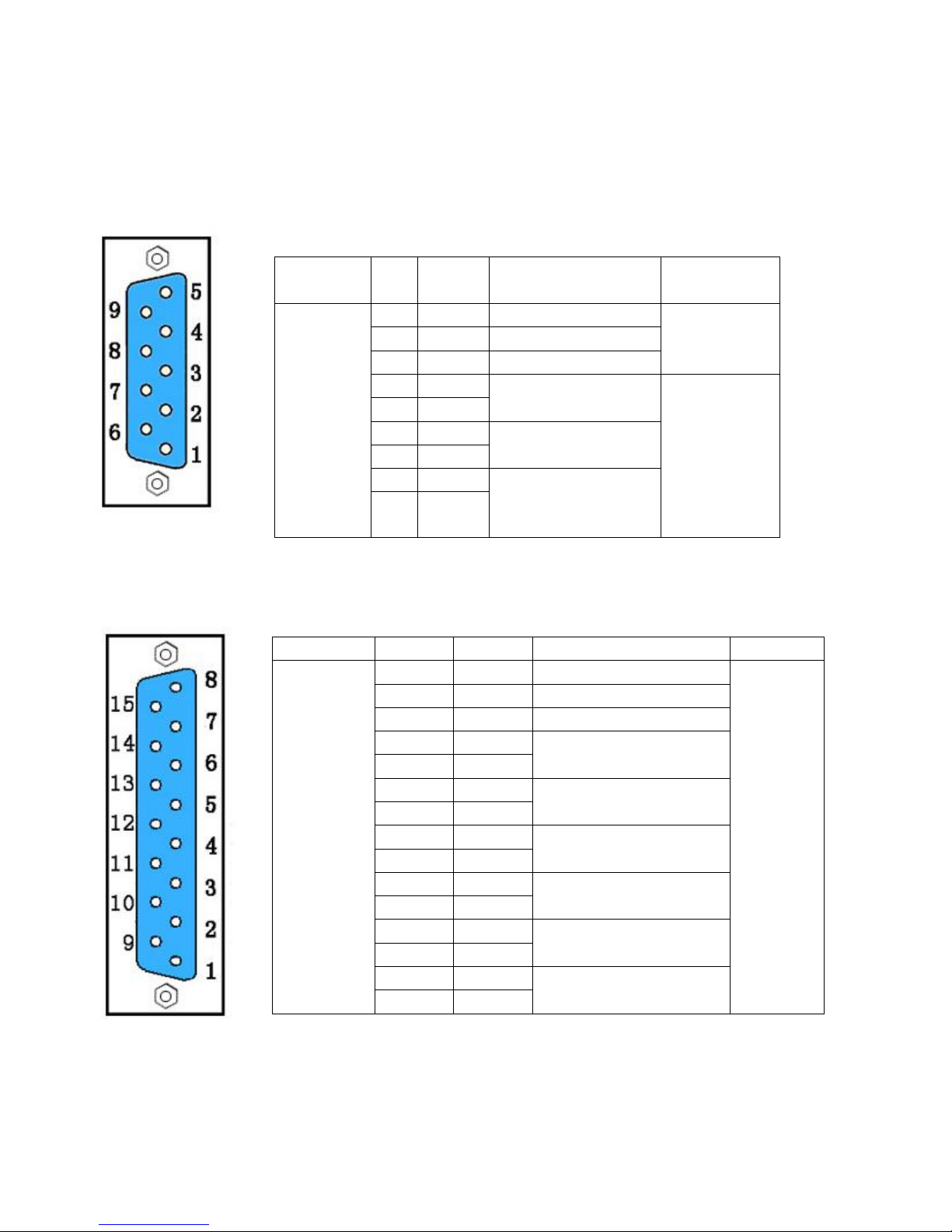
3.5 X3/X4 Interfaces of CD Driver
3.5.1 X3 Interface
3.5.2 X4 Interface
Interface
Pin
No.
Signal
Description
Function
X3
(9-pin
female
connector)
1
RXD
To receive data
RS232
communication
interface
5
TXD
To transmit data
6
GND
Ground of signal
2
A
To output phase-A
signal of encoder
Output
interface of
encoder in
motor
7
/A 3 B
To output phase-B
signal of encoder
8
/B 4 N
To output index
signal(Z signal) of
encoder
9
/N
Interface
Pin No.
Signal
Description
Function
X4
(15-pin
female
connector)
1
+5V
To output 5 V voltage
Input
interface of
encoder in
motor
9
GND
0 V 8 NC
N/A 2 A
To input phase-A signals
of encoder
10
/A 3 B
To input phase-B signals
of encoder
11
/B 4 N
To input phase-Z signals
of encoder
12
/N 5 U
To input phase-U signals
of encoder
13
/U 6 V
To input phase-V signals
of encoder
14
/V 7 W
To input phase-W signals
of encoder
15
/W
Page 18
18
Chapter 4 Digital Operation Panel
4.1 Introduction
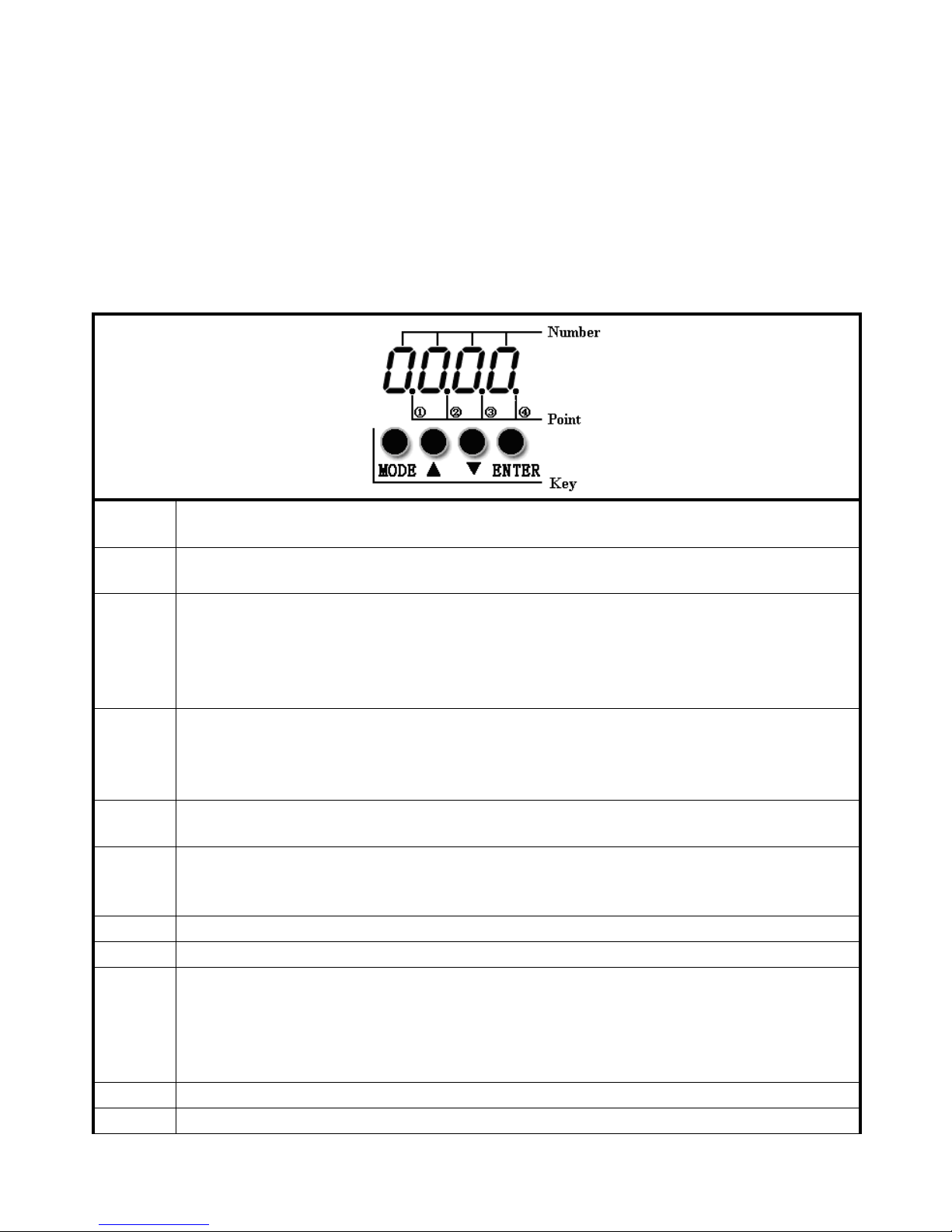
A digital operation panel functions to set user parameters in a servo driver, execute instructions, or display
parameters. Table 4-1 describes all display contents and functions of the digital operation panel.
Table 4-1 Display contents and functions of a digital operation panel
Number/
Point/Key
Function
①
Indicates whether data is positive or negative. If it is on, it indicates negative; otherwise it indicates
positive.
②
1. Distinguishes the current object group and the address data in this object group during
parameter settings.
2. Indicates the higher 16 bits of the current 32-bit data when internal 32-bit data is displayed in
real time.
3. Indicates the earliest error when history records of errors (F007) are displayed.
③
1. Indicates a data display format when parameters are displayed and adjusted in real time. If it is
on, it indicates the data is displayed in hexadecimal; otherwise it indicates the data is
displayed in decimal.
2. Indicates the latest error when the history records of errors (F007) are displayed.
④
1. If it is on, it indicates that internal data is currently displayed.
2. If it flickers, it indicates that the power part of the driver is in the working status.
MODE
1. Switches basic menus.
2. During the adjustment of parameters, short presses the key to move the bit to be adjusted, and
long presses the key to return to the previous state.
▲
Presses ▲ to increase set values; long presses ▲ to increase numbers promptly.
▼
Presses ▼ to decrease set values; long presses ▼ to decrease numbers promptly.
ENTER
1. Enters the selected menu by pressing this key.
2. Keeps current parameters in the enabled status.
3. Confirms input parameters after parameters are set.
4. Long presses this key to switch to higher/lower 16 bits when internal 32-bit data is displayed in
real time.
P..L
Activates position positive limit signals.
n..L
Activates position negative limit signals.
Page 19

19
Pn.L
Activates position positive/negative limit signals.
Overall
Flicking
Indicates that an error occurs on the driver, and is in the alarm state.
If the parameter adjusting display mode is featured by the decimal system:
When the units place is flickering, press ▲ to add 1 to the current value; press ▼ to deduct 1 from the
current value. When the tens place is flickering, press ▲ to add 10 to the current value; press ▼ to deduct 10
from the current value. When the hundreds place is flickering, press ▲ to add 100 to the current value; press ▼
to deduct 100 from the current value. When the thousands place is flickering, press ▲ to add 1000 to the current
value; press ▼ to deduct 1000 from the current value.
If the parameter adjusting display mode is featured by the hexadecimal system:
When the units place is flickering, press ▲ to add 1 to the current value; press ▼ to deduct 1 from the
current value. When the tens place is flickering, press ▲ to add 0X10 to the current value; press ▼ to deduct
0X10 from the current value. When the hundreds place is flickering, press ▲ to add 0X100 to the current value;
press ▼ to deduct 0X100 from the current value. When the thousands place is flickering, press ▲ to add 0X1000
to the current value; press ▼ to deduct 0X1000 from the current value.
When adjusting decimal parameters, the display mode is automatically switched to the hexadecimal system
if the data is greater than 9999 or less than -9999. In this case, the 3rd decimal point from left to right is
highlighted.
Page 20
20
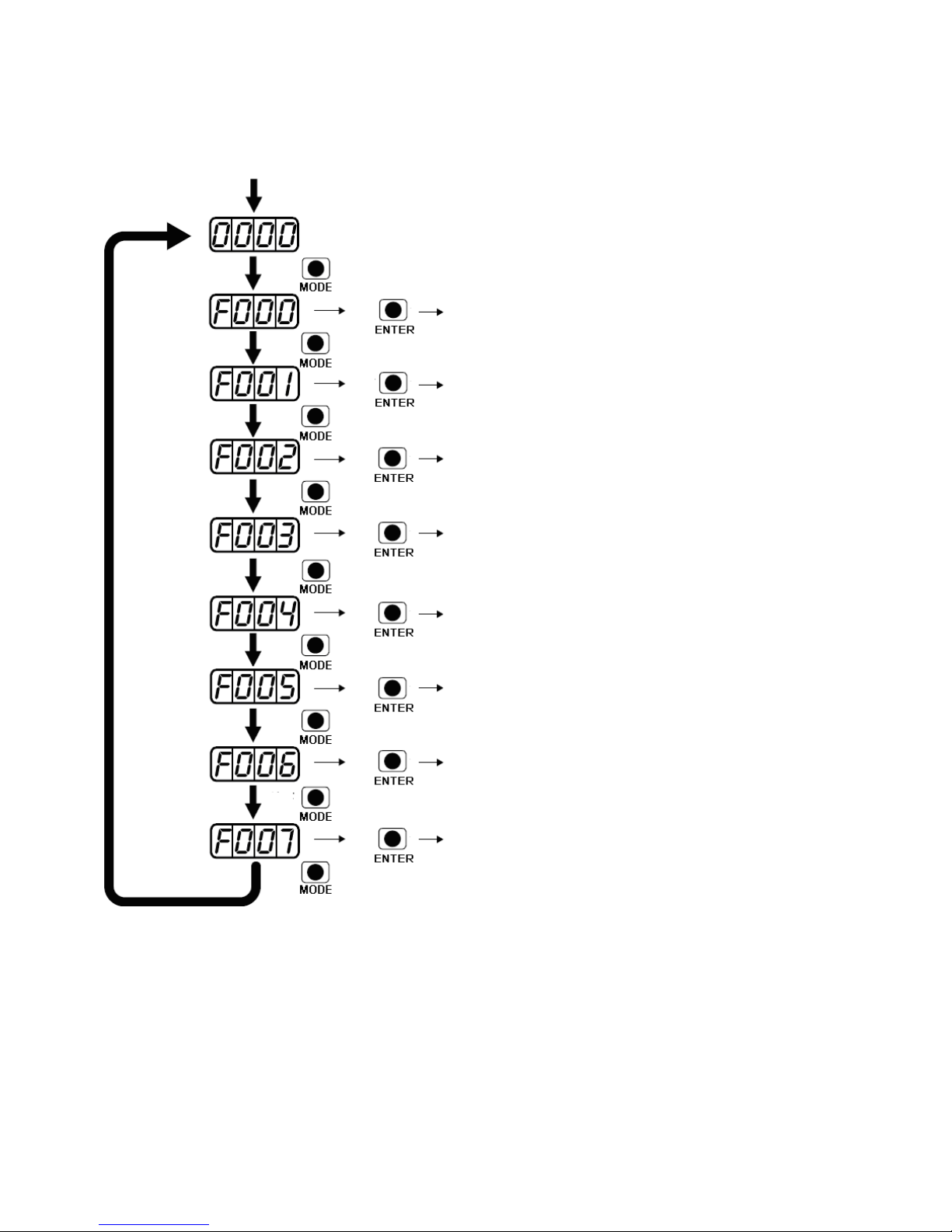
4.2 Operation on Digital Operation Panel
Power ON
Press MODE
Switching of basic menus
Parameter display (current speed is
displayed by default)
Press
Press
Press
Press
Press
Press
Press
Press
Press
Press
Press
Press
Press
Press
Press
Press
Press
Set driver instructions
Set real-time display of data
Set control loop parameters
Settings
I/O parameters
Mode operation parameters
Set motor parameters
Set driver parameters
Trial operation
Check wrong history records
Loop
Fig. 4-1 Operation on a digital operation panel
Note: If a non real-time display interface is displayed for the control panel, and no key operation occurs, the
real-time display interface is automatically skipped after 20 seconds to avoid misoperation.
Example 4-1: Set the denominator of electronic gear ratio to 10000 with
number system switching
1. Press MODE. The main menu is displayed. Choose F003.
Page 21
21
2. Press ENTER. The interface for selecting addresses is displayed.
3. Press ▲ to adjust data as d3.35.
4. Press ENTER to display the current value d3.35. Press ENTER again to modify the value d3.35. In this case,
the 1st number at the right side is flickering. Short press MODE for three times to move to the first position on
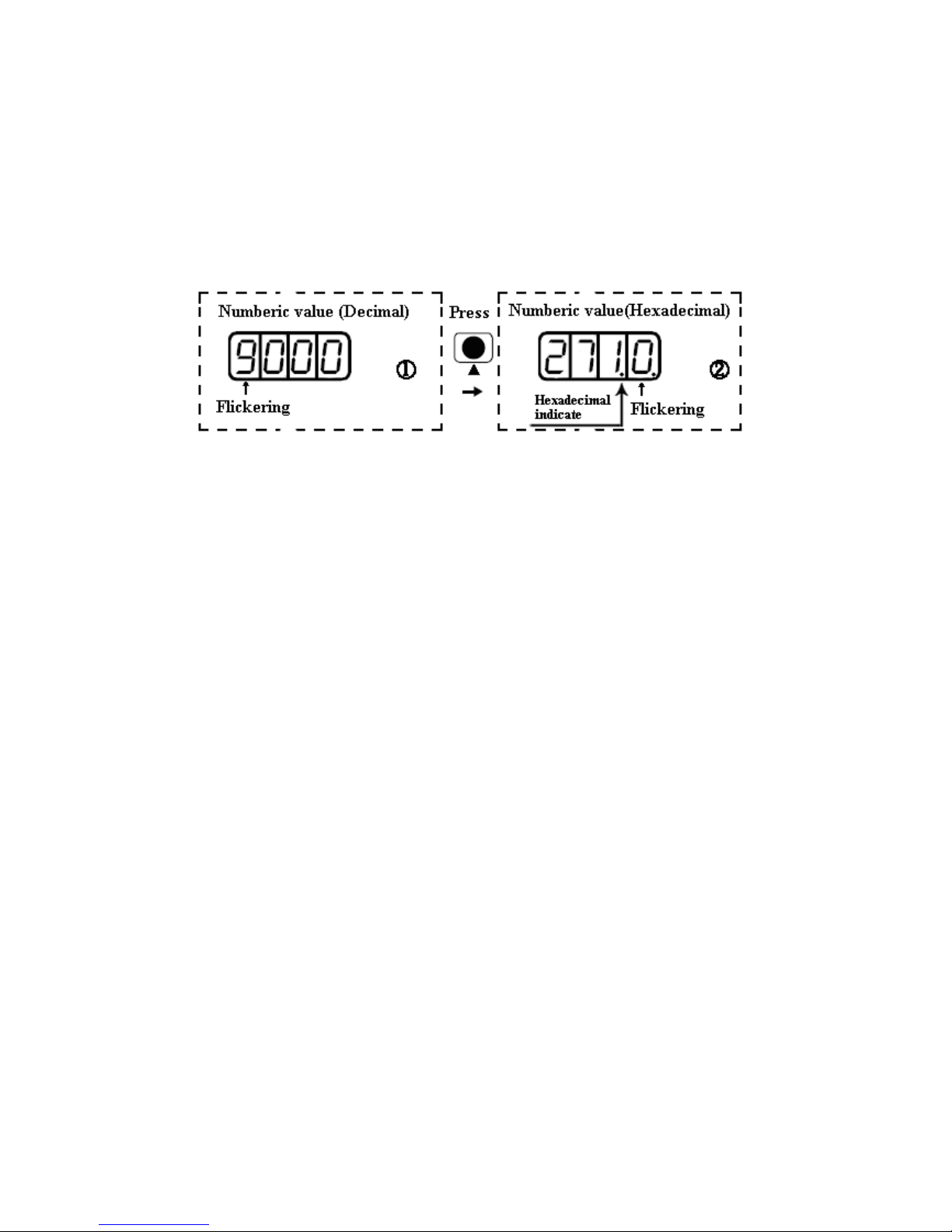
the left. Then press ▲. The value is increased to 9000. In this case, the current data is decimal.
5. Press ▲ again. The content of numeric display changes to ―271.0‖, and the 3rd decimal point (from left to
right) flickers. In this case, the data is hexadecimal. Press ENTER to confirm the current value. The 1st
decimal point on the right flickers. In this case, the denominator of the electronic gear ratio is modified to
10000.
Fig. 4-2 Number system conversion
Example 4-2: Set the speed to 1000 RPM/-1000 RPM with separate regulation of
bits
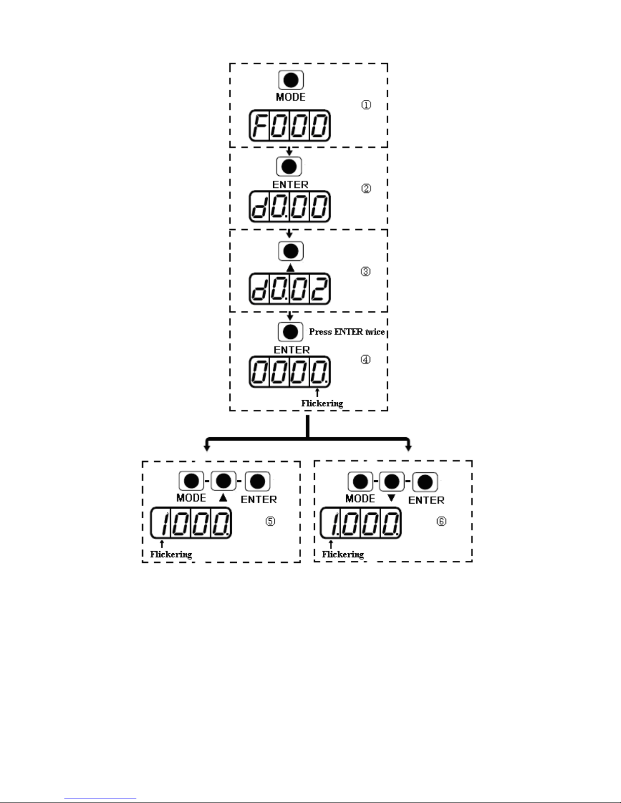
1. Press MODE. The main menu is displayed. Choose F000.
2. Press ENTER. The interface for selecting addresses is displayed.
3. Press ▲ to adjust data as d0.02.
4. Press ENTER to display the current value d0.02. Press ENTER again to modify the value d0.02. In this case,
the 1st number at the right side is flickering.
5. Short press MODE for three times to move to the 1st position on the left. Press ▲ to modify the value to 1.
Press ENTER to confirm the current value. The 1st decimal point on the right flickers. In this case, the speed
is 1000 RPM.
6. Press ▼ to modify the value to -1. In this case, the 1st decimal point on the left flickers, indicating that the
current data is negative. Press ENTER to confirm the current value. The 1st decimal point on the right flickers.
In this case, the speed is -10000 RPM.
Page 22
22
Fig. 4-3 Separate regulation of bits
Page 23

23
Chapter 5 Trial Operation & Parameter Introduction
5.1 Trial Operation
5.1.1 Objective
The trial operation allows you to test whether the driver works properly, and whether the motor runs stably.
5.1.2 Precautions
1. Ensure that the motor is running without load. If the motor flange is fixed on the machine, ensure that the
motor shaft is disconnected from the machine.
2. Ensure that motor cables, motor encoder cables, and power circuits (power lines and control power lines)
are properly connected. For details, see Chapter 3.
3. During the trial operation, if you long press ▲ or ▼ when the motor is running, pulse signals, digital input
signals, and analog signals of the external controller are temporarily unavailable, so safety must be ensured.
4. During the trial operation, the system automatically adopts the instantaneous speed mode, that is, the ―-3‖
mode.
5. After the trial operation, Group F006 exits automatically. To enter Group F006 again, you must re-activate the
trial operation.
6. If motor/encoder cables are wrongly connected, the actual rotation speed of the motor may be the possible
maximum rotation speed, or the rotation speed is 0 and the actual current value is the maximum value. In
this case, make sure to release the button; then check cable connection and test it again.
5.1.3 Operating Steps
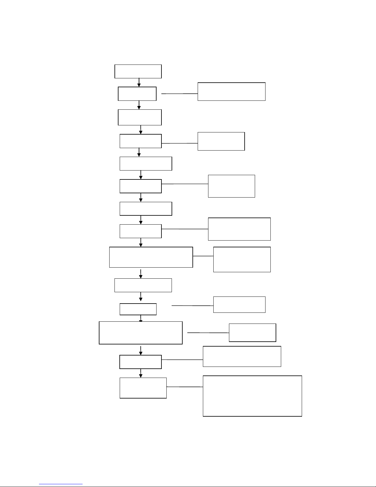
1. Press MODE to enter Group F004. Select the object address ―d4.18‖, and check the motor type.
2. Press MODE to enter Group F000. Select the object address ―d0.02‖, and set the target speed to
―SpeedDemand_RPM".
3. Press MODE to enter Group F006. Arrange a test for keys, with the default value of d6.40. Firstly, press ▼ to
adjust the data to d6.31. Then, press ▼, the data automatically changes to ―d6.15‖. Finally, press ▲ to adjust
the data to d6.25.
4. Press ENTER to activate trial operation. In this case, the numeric display is ―adc.d‖, and the motor shaft
releases. When long pressing ▲ or ▼, the motor automatically locks, and runs according to
―+SpeedDemand_RPM‖ or ―-SpeedDemand_RPM‖ separately. During the trial operation, the numeric
displays the motor speed in real time.
Page 24
24
5.1.4 Diagram of Trial Operation
5.1.1 Diagram of trial operation
Press MODE
F000
Enter the list of driver
instructions
Press ENTER
d0.02
Choose speed instructions
Set target speed (Unit: RPM)
(Refer to the example of setting the speed)
Press MODE
F006
Enter the trial operation
—Press ▼ to change d6.40 to d6.31 (press ▼ again
to change to d6.15); press ▲ to change to d6.25
Activate trial operation
Numeric display is ―abc.d‖
Long press ▲ or ▼
The motor works at the set target speed. Long pressing ▲
indicates that the motor works in the counterclockwise (positive)
direction; and long pressing ▼ indicates that the motor works in
the clockwise (negative) direction.
d4.18
Check motor types
Press MODE
F004
Press ENTER
Enter the list of motor parameters
Both positive and negative
speed can be set
Press ENTER
Test on keys
Page 25

25
5.2 Description of Parameters
Group F000 represents an instruction group, and the parameters in this group cannot be saved.
The address d4.00 is used to save the motor parameters set for Group F004. Note that this group of
parameters must be set when customers choose third-party motors, but these parameters need not to be set for
the motors delivered and configured by our company. d2.00, d3.00 and d.5.00 represent the same address, and
are used to save all setup parameters except those of motors (Group F001/F002/F003/F004/F005). Three
numeric objects (d2.00/d3.00/d5.00) are developed to facilitate customers.
Parameter List: Group F000 (To Set Driver Instructions)
Numeric
Display
Internal
Address
Variable Name
Meaning
Default
Value
Range
d0.00
60600008
Operation_Mode
0.004 (-4): Pulse control mode, including
pulse direction (P/D) and double pulse
(CW/CCW) modes. 0.003 (-3):
instantaneous speed mode
0001 (1): Internal position control mode
0003 (3): Speed mode with
acceleration/deceleration
0004 (4): Torque mode
Note: Only applied in the working mode
where no external signals control the
driver.
-4
N/A
d0.01
2FF00508
Control_Word_E
asy
000.0: Releases the motor
000.1: Locks the motor
001.0: Clears errors
Note: Only applied in the situation where
enabling a driver or wrong resetting is
not controlled by external signals. After
the wrong reset of the driver, the motor
must be enabled again.
0
N/A
d0.02
2FF00910
SpeedDemand_
RPM
Sets the motor’s target rotation speed
when the driver works in the ―-3‖ or ―3‖
mode and the address d3.28 is set to 0
(without external analog control).
0
N/A
d0.03
60710010
CMD_q
Sets input torque instructions (current
instructions) when the driver works in
the ―4‖ mode and the address d3.30 is
set to 0 (without external analog
control).
0
-2047~2047
d0.04
2FF00A10
Vc_Loop_BW
Sets the velocity loop bandwidth. The
unit is Hz.
This variable can only be set after auto
tuning is performed properly; otherwise
0
0~600
Page 26
26
the actual bandwidth goes wrong, which
causes abnormal working of the driver.
If the auto tuning result is abnormal,
setting this parameter may also cause
abnormal working of the driver.
Note: This parameter cannot be applied
when auto tuning is unavailable. After
setting this parameter, apply d2.00 to
save the settings as required.
d0.05
2FF00B10
Pc_Loop_BW
Sets the position loop bandwidth. The
unit is Hz.
Note: After setting this parameter, apply
d2.00 to save the settings as required.
0
N/A
d0.06
2FF00C10
Tuning_Start
If the variable is set to 11, auto tuning
starts. All input signals are neglected
during auto tuning. The variable is
automatically changed to 0 after auto
tuning is completed.
Sets the variable to other values to end
auto tuning.
0
N/A
Page 27
27
Parameter List: Group F001 (To Set Real-Time Display Data)
Numeric
Display
Internal Address
Variable Name
Displayed Content
d1.00
2FF00F20
Soft_Version_LED
Software version of numeric display
d1.01
2FF70020
Time_Driver
Accumulated working time of the driver
(S)
d1.02
2FF01008
Motor_IIt_Rate
Ratio of real iit to the maximum iit of a
motor
d1.03
60F61210
Motor_IIt_Real
Actual data of motor overheat protection
peak
rms
I
Motor_IIt_Real*512
I*
2047
2
d1.04
2FF01108
Driver_IIt_Rate
Ratio of real iit to the maximum iit of a
driver
d1.05
60F61010
Driver_IIt_Real
Actual data of driver overheat protection
d1.06
2FF01208
Chop_Power_Rate
Ratio of actual power to rated power of a
braking resistor
d1.07
60F70D10
Chop_Power_Real
Actual power of a braking resistor
d1.08
60F70B10
Temp_Device
Temperature of a driver (°C)
d1.09
60790010
Real_DCBUS
Actual DC bus voltage
d1.10
60F70C10
Ripple_DCBUS
Fluctuating value of the bus voltage
(Vpp)
d1.11
60FD0010
Din_Status
Status of an input port
d1.12
20101410
Dout_Status
Status of an output port
d1.13
25020F10
Analog1_out
Filter output of external analog signal 1
d1.14
25021010
Analog2_out
Filter output of external analog signal 2
d1.15
26010010
Error_State
Error state
d1.16
26020010
Error_State2
Error state word 2
d1.17
60410010
Status_Word
Driver status word
d1.18
60610008
Operation_Mode_Buff
Efficient working mode of a driver
d1.19
60630020
Pos_Actual
Actual position of a motor
d1.20
60FB0820
Pos_Error
Position following error
d1.21
25080420
Gear_Master
Count of input pulses before electronic
gear
d1.22
25080520
Gear_Slave
Count of executed pulses after electronic
gear
d1.23
25080C10
Master_Speed
Pulse speed entered by the master axis
(pulse/mS)
d1.24
25080D10
Slave_Speed
Pulse speed of the slave axis (pulse/mS)
d1.25
606C0010
Real_Speed_RPM
Real speed (rpm)
Internal sampling time: 200 mS
d1.26
60F919
Real_Speed_RPM2
Real speed (0.01 rpm)
Internal sampling time: 200 mS
Page 28
28
d1.27
60F91A10
Speed_1mS
Speed data (inc/1 mS)
Internal sampling time: 1 mS
d1.28
60F60C10
CMD_q_Buff
Internal effective current instruction
d1.29
60F61710
I_q
Actual current
peak
rms
I
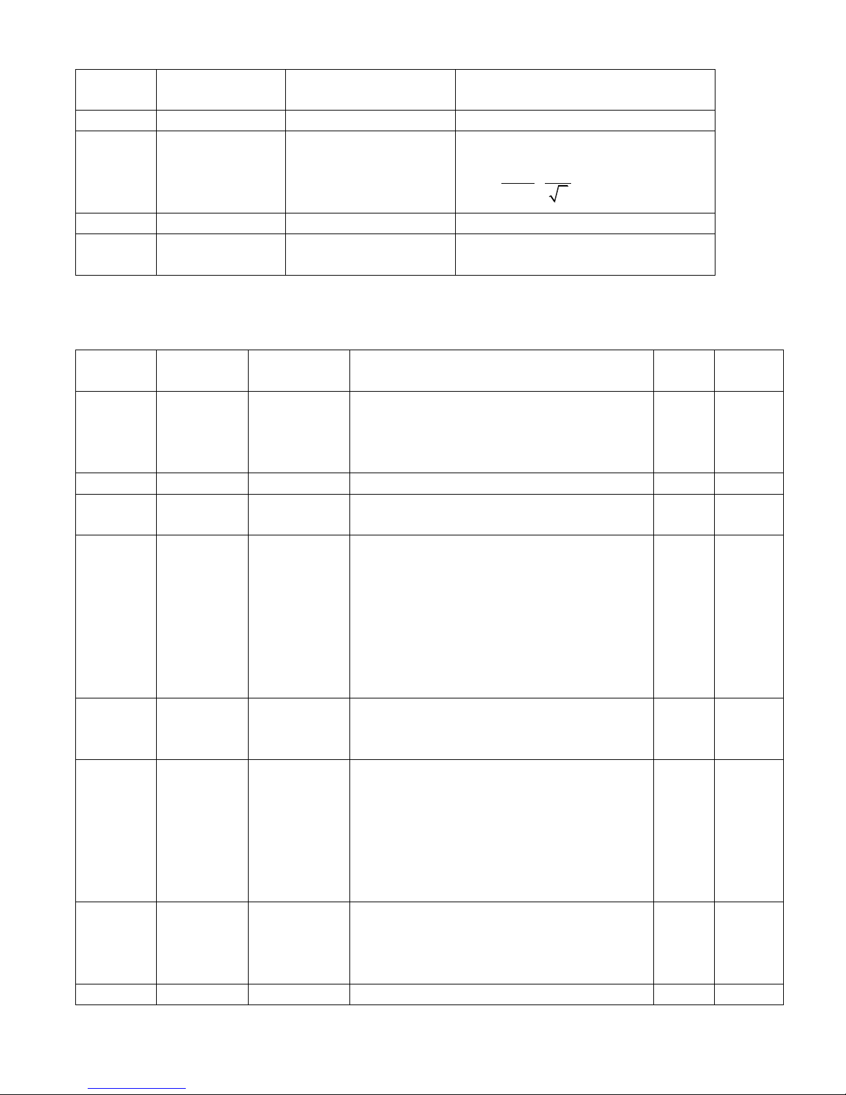
_
I*
2047
2
Iq
d1.30
60F90E10
K_Load
Load parameter
d1.31
301004
Z_Capture_Pos
Position data captured by encoder index
signals
Parameter List: Group F002 (To Set Control Loop Parameters)
Numeric
Display
Internal
Address
Variable
Name
Meaning
Default
Value
Range
d2.00
2FF00108
Store_Loop_
Data
1: Stores all setup parameters except those of a
motor
10: Initializes all setup parameters except those
of a motor
0
N/A
d2.01
60F90110
Kvp
Sets the response speed of velocity loop
100
0~32767
d2.02
60F90210
Kvi
Time used to adjust speed control to
compensate minor errors
2
0~16384
d2.03
60F90308
Notch_N
Notch/filtering frequency setting for a velocity
loop, used to set the frequency of the internal
notch filter, so as to eliminate the mechanical
resonance produced when the motor drives the
machine. The formula is F=Notch_N*10+100.
For example, if the mechanical resonance
frequency is F = 500 Hz, the parameter should
be set to 40.
45
0~90
d2.04
60F90408
Notch_On
Enable or disable the notch filter
0: Disable the trap filter
1: Enable the trap filter
0
N/A
d2.05
60F90508
Speed_Fb_N
You can reduce the noise during motor
operation by reducing the feedback bandwidth
of velocity loop. When the set bandwidth
becomes less, the motor responds slower.
The formula is F=Speed_Fb_N*20+100.
For example, to set the filter bandwidth to "F =
500 Hz‖, you need to set the parameter to 20.
45
0~45
d2.06
60F90608
Speed_Mode
0: Speed response after traveling through a
low-pass filter
1: Direct speed response without filtering
2: Feedback on output feedback
0
N/A
d2.07
60FB0110
Kpp
Proportional gains on position loop Kpp
1000
0~16384
Page 29
29
d2.08
60FB0210
K_Speed_FF
0 indicates no feedforward, and 256 indicates
100% feedforward
256
0~256
d2.09
60FB0310
K_Acc_FF
The data is inversely proportional to the
feedforward
7FF.F
32767~1
0
d2.10
2FF00610
Profile_Acce_
16
To set trapezoidal acceleration (rps/s) in the ―3‖
and ―1‖ modes
610
0~2000
d2.11
2FF00710
Profile_Dece_
16
To set trapezoidal deceleration (rps/s) in the ―3‖
and ―1‖ modes
610
0~2000
d2.12
60F60110
Kcp
To set the response speed of the current loop
and this parameters does not require adjusting
N/A
N/A
d2.13
60F60210
Kci
Time used to adjust current control to
compensate minor errors
N/A
N/A
d2.14
60730010
CMD_q_Max
Indicates the maximum value of current
instructions
N/A
N/A
d2.15
60F60310
Speed_Limit_
Factor
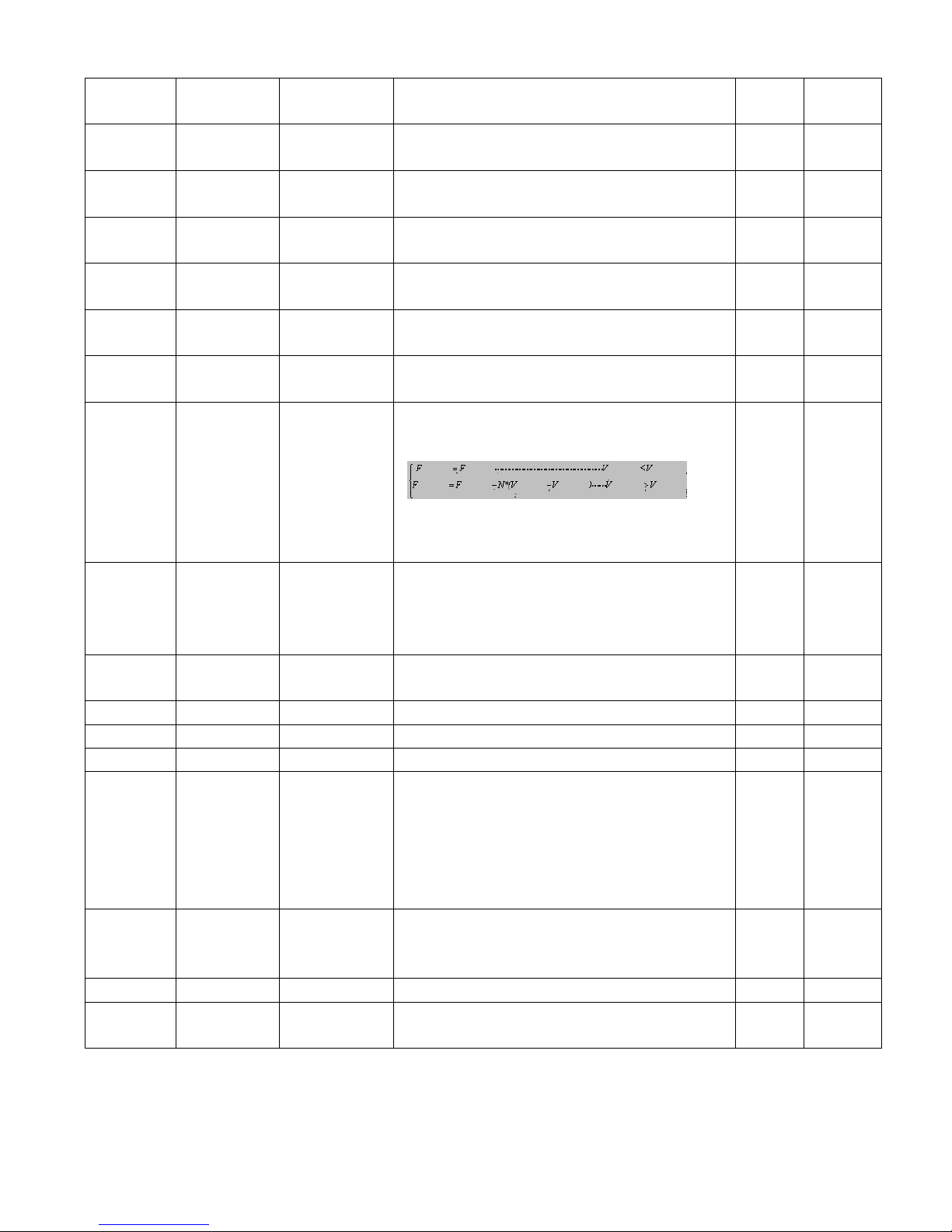
The factor that limits the maximum speed in the
torque mode
Actual torque
Set torque
Actual torque Set torque
Actual speed Maximum speed
Actual speed
Actual speed
Maximum speed
Maximum speed
V the maximum speed complies with d2.24
Max_Speed_RPM parameter settings
10
0~1000
d2.16
607E0008
Invert_Dir
Runs polarity reverse
0: Counterclockwise indicates the forward
direction
1: Clockwise indicates the forward direction
0
N/A
d2.17
60F90E10
K_Load
Indicates load parameters
N/A
20~1500
0
d2.18
60F90B10
Kd_Virtual
Indicates the kd of observers
1000
0~32767
d2.19
60F90C10
Kp_Virtual
Indicates the kp of observers
1000
0~32767
d2.20
60F90D10
Ki_Virtual
Indicates the ki of observers
0
0~16384
d2.21
60F91010
Sine_Amplitu
de
Proper increase in this data will reduce the
tuning error, but machine vibration will become
severer. This data can be adjusted properly
according to actual conditions of machines. If
the data is too small, the auto tuning error
becomes greater, or even causes a mistake.
64
0~1000
d2.22
60F91110
Tuning_Scale
It is helpful to reduce the auto tuning time by
reducing the data, but the result may be
unstable.
128
0~16384
d2.23
60F91210
Tuning_Filter
Indicates filter parameters during auto-tuning
64
1~1000
d2.24
60800010
Max_Speed_
RPM
Limits the maximum rotation speed of motors
5000
0~6000
Page 30
30
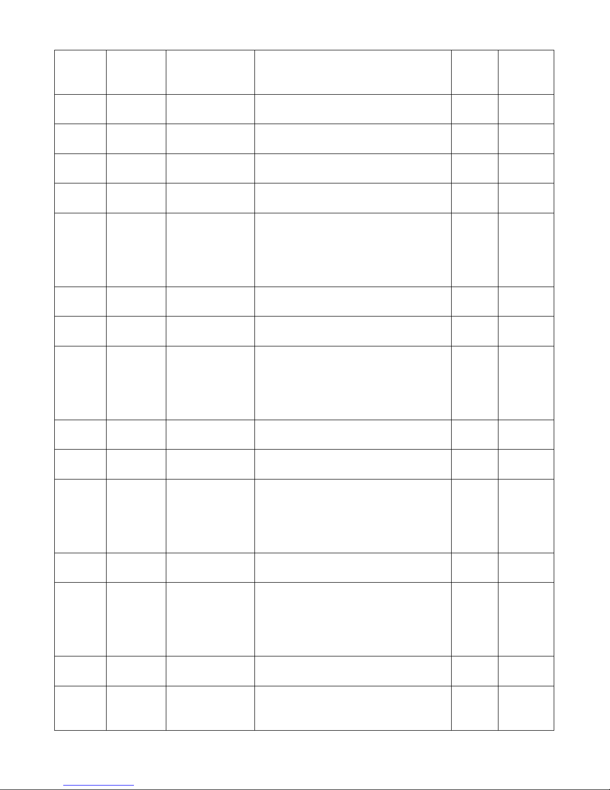
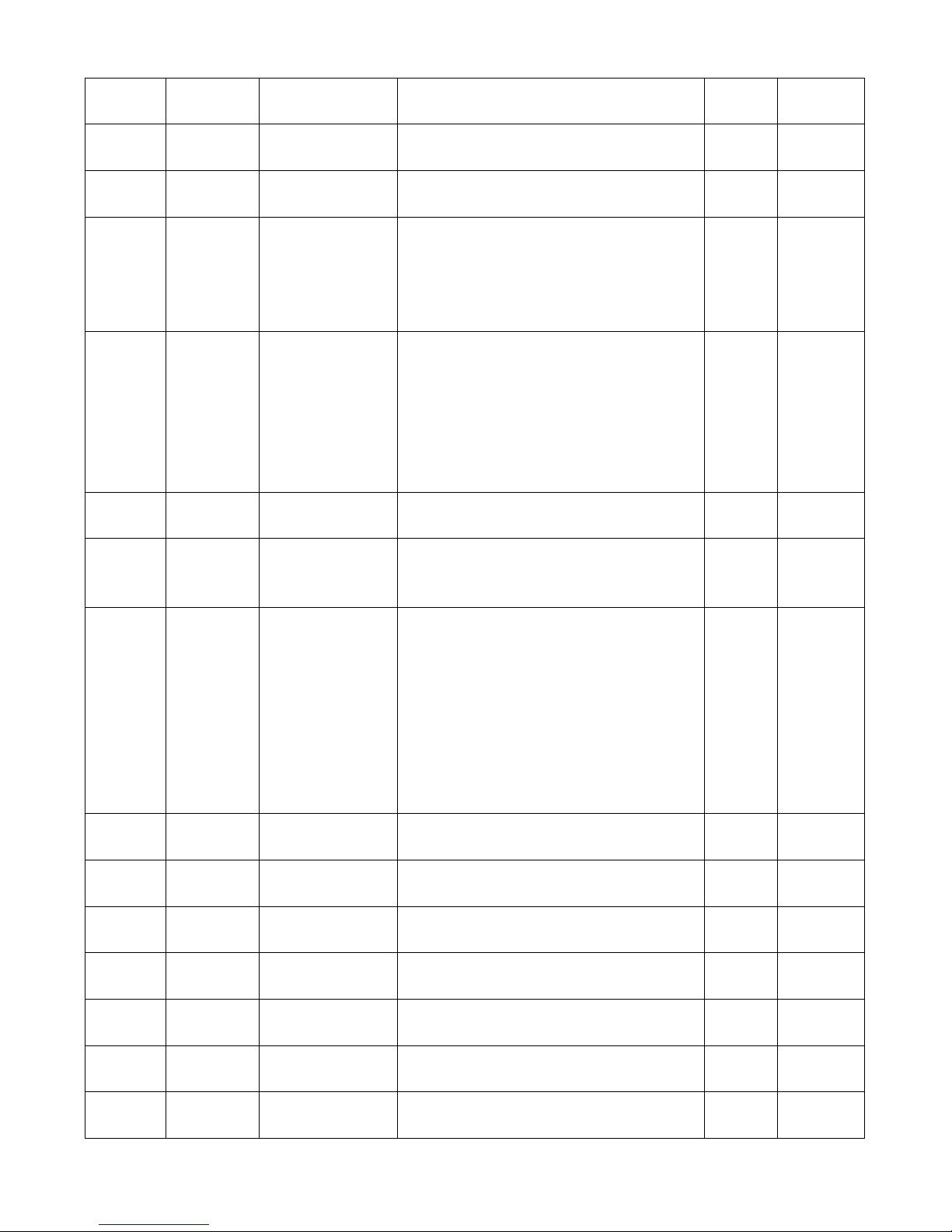
Parameter List: Group F003 (To Set Input/Output & Pattern Operation
Parameters)
Numeric
Display
Internal
Address
Variable Name
Meaning
Default
Value
Range
d3.00
2FF00108
Store_Loop_Data
1: Stores all setup parameters except
motors
10: Initializes all setup parameters except
motors
0
N/A
d3.01
20100310
Din1_Function
000.1: Driver enable
000.2: Driver fault reset
000.4: Operation mode control
000.8: P control for velocity loop
001.0: Position positive limit
002.0: Position negative limit
004.0: Homing signal
008.0: Reverse speed demand
010.0: Internal speed control 0
020.0: Internal speed control 1
040.0: Internal position control 0
080.0: Internal position control 1
100.0: Quick stop
000.1
N/A
d3.02
20100410
Din2_Function
000.2
N/A
d3.03
20100510
Din3_Function
000.4
N/A
d3.04
20100610
Din4_Function
000.8
N/A
d3.05
20100710
Din5_Function
001.0
N/A
d3.06
20100810
Din6_Function
002.0
N/A
d3.07
20100910
Din7_Function
004.0
N/A
d3.08
20100110
Dio_Polarity
Sets IO polarity
0
N/A
d3.09
2FF00810
Dio_Simulate
Simulates input signals, and enforce
output signals for outputting
0
N/A
d3.10
20000008
Switch_On_Auto
Automatically locks motors when drivers
are powered on
0: No control
1: Automatically locks motors when drivers
are powered on
0
N/A
d3.11
20100F10
Dout1_Function
000.1: Ready
000.2: Error
000.4: Position reached
000.8: Zero velocity
001.0: Motor brake
002.0:Velocity reached
004.0: Index
008.0: The maximum speed obtained in
the torque mode
010.0: PWM ON
000.1
N/A
d3.12
20101010
Dout2_Function
000.2
N/A
d3.13
20101110
Dout3_Function
00a.4
N/A
d3.14
20101210
Dout4_Function
000.8
N/A
d3.15
20101310
Dout5_Function
001.0
N/A
d3.16
20200D08
Din_Mode0
If a digital input is defined as Operation
mode control,then this operation mode is
selected when the input signal is invalid
-4
N/A
Page 31
31
d3.17
20200E08
Din_Mode1
If a digital input is defined as Operation
mode control,then this operation mode is
selected when the input signal is valid
-3
N/A
d3.18
20200910
Din_Speed0_RP
M
Multi-speed control: 0 [rpm]
0
N/A
d3.19
20200A10
Din_Speed1_RP
M
Multi-speed control: 1 [rpm]
0
N/A
d3.20
20200B10
Din_Speed2_RP
M
Multi-speed control: 2 [rpm]
0
N/A
d3.21
20200C10
Din_Speed3_RP
M
Multi-speed control: 3 [rpm]
0
N/A
d3.22
25020110
Analog1_Filter
Used to smooth the input analog signals
F (Filter Frequency) = 4000/ (2π*
Analog1_Filter)
Τ (Time Constant) = Analog1_Filter/4000
(S)
5
1~127
d3.23
25020210
Analog1_Dead
Sets dead zone data for external analog
signal 1
0
0~8192
d3.24
25020310
Analog1_Offset
Sets offset data for external analog signal
1
0
-8192~81
92
d3.25
25020410
Analog2_Filter
Used to smooth the input analog signals
Filter frequency: f=4000/(2π*
Analog1_Filter)
Time Constant: T = Analog1_Filter/4000
(S)
5
1~127
d3.26
25020510
Analog2_Dead
Sets dead zone data for external analog
signal 2
0
0~8192
d3.27
25020610
Analog2_Offset
Sets offset data for external analog signal
2
0
-8192~81
92
d3.28
25020708
Analog_Speed_C
on
Chooses analog-speed channels
0: Invalid analog channel
1: Valid analog channel 1 (AIN1)
2: Valid analog channel 2 (AIN2)
Valid mode -3 and 3
0
N/A
d3.29
25020A10
Analog_Speed_F
actor
Sets the proportion between analog
signals and output speed
1000
N/A
d3.30
25020808
Analog_Torque_
Con
Chooses analog-torque channels
0: Invalid analog channel
1: Valid analog channel 1 (AIN1)
2: Valid analog channel 2 (AIN2)
Valid mode 4
0
N/A
d3.31
25020B10
Analog_Torque_F
actor
Sets the proportion between analog
signals and output speed (current)
1000
N/A
d3.32
25020908
Analog_MaxT_C
on
0: No control
1: Max. torque controlled by AIN 1
2: Max. torque controlled by AIN 2
0
N/A
Page 32
32
d3.33
25020C10
Analog_MaxT_Fa
ctor
Indicates the max torque factor on analog
signal control
8192
N/A
d3.34
25080110
Gear_Factor
Indicates the numerator to set electronic
gears when the operation mode is -4
1000
-32767~3
2767
d3.35
25080210
Gear_Divider
Indicates the denominator to set electronic
gears when the operation mode is -4
1000
1~32767
d3.36
25080308
PD_CW
0: Double pulse (CW/CCW) mode
1. Pulse Direction (P/D) mode
Note: To change this parameter, you need
to save it with the address ―d5.00‖, and
restarts it later.
1
N/A
d3.37
25080610
PD_Filter
To flat the input pulse.
Filter frequency: f=1000/(2π* PD_Filter)
Time constant: T = PD_Filter/1000
Unit: S
Note: If you adjust this filter parameter
during the operation, some pulses may be
lost.
3
1~32767
d3.38
25080810
Frequency_Chec
k
Indicates the limitation on pulse input
frequency (k Hz)
600
0~600
d3.39
25080910
PD_ReachT
Indicates the position reached time window
in the pulse mode
Unit: mS
10
0~32767
d3.40
2FF10108
Panel32_N
To select which parameter will be set.
0. Din_Pos0
1. Din_Pos1
2. Din_Pos2
3. Din_Pos3
4. Din_Pos4
5. Din_Pos5
6. Din_Pos6
7. Din_Pos7
0
N/A
d3.41
2FF10210
Panel32_H
The high part of Din_Pos.
Din_Pos=Panel32_H*10000+Panel32_L
0
-32767~3
2767
d3.42
2FF10310
Panel32_L
The low part of Din_Pos.
Din_Pos =Panel32_H*10000+Panel32_L
0
-32767~3
2767
d3.43
20200F10
Din_Control_Wor
d
Input ―Enable‖ signal controls the control
word.
0
N/A
d3.44
20201810
Din_Speed4_RP
M
Multi-speed control: 4 [rpm]
0
N/A
d3.45
20201910
Din_Speed5_RP
M
Multi-speed control: 5 [rpm]
0
N/A
d3.46
20201A10
Din_Speed6_RP
M
Multi-speed control: 6 [rpm]
0
N/A
d3.47
20201B10
Din_Speed7_RP
M
Multi-speed control: 7 [rpm]
0
N/A
Page 33
33
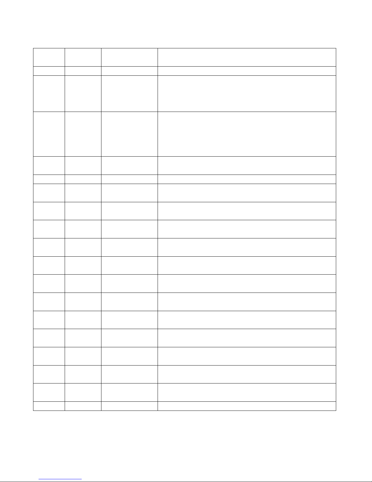
Parameter List: Group F004 (To Set Motor Parameters)
Numeric
display
Internal
Address
Variable Name
Meaning
d4.00
2FF00308
Store_Motor_Data
1: Stores the set motor parameters
d4.01
64100110
Motor_Num
Host computer (ASCII code) numerical display (hexadecimal)
―00‖..... ..... ...303.0
Note: To change this parameter, you need to save it with the
address ―d4.00‖, and restart it later.
d4.02
64100208
Feedback_Type
Type of encoders
001.1: Differential ABZ and differential UVW signals
001.0: Differential ABZ and UVW signals of TTL
000.1: ABZ of TTL and differential UVW signals
000.0: ABZ of TTL and UVW signals of TTl
d4.03
64100508
Motor_Poles
Number of motor poles pairs
[2p]
d4.04
64100608
Commu_Mode
Searching excitation mode
d4.05
64100710
Commu_Curr
Searching excitation current
[dec]
d4.06
64100810
Commu_Delay
Delay in searching excitation
[mS]
d4.07
64100910
Motor_IIt_I
Indicates current settings on overheat protection of motors
Ir[Arms]*1.414*10
d4.08
64100A10
Motor_IIt_Filter
Indicates time settings on overheat protection of motors
Time: N*256/1000 Unit: S
d4.09
64100B10
Imax_Motor
Indicates max peak current of motors
I[Apeak]*10
d4.10
64100C10
L_Motor
Indicates phase inductance of motors
L[mH]*10
d4.11
64100D08
R_Motor
Indicates phase resistance of motors
R[Ω]*10
d4.12
64100E10
Ke_Motor
Indicates the reverse electromotive force of motors
Ke[Vp/krpm]*10
d4.13
64100F10
Kt_Motor
Indicates the torque coefficient of motors
Kt[Nm/Arms]*100
d4.14
64101010
Jr_Motor
Indicates the rotor inertia of motors
Jr[kgm^2]*1 000 000
d4.15
64101110
Brake_Duty_Cycle
Indicates the duty cycle of contracting brakes
0~2500[0…100%]
d4.16
64101210
Brake_Delay
Indicates the delay time of contracting brakes
Default value: 150 ms
d4.17
64101308
Invert_Dir_Motor
Indicates the rotation direction of motors
Page 34
34
d4.18
64101610
Motor_Using
Current using motor type.
PC Software Numeric Display Model
"K0".........................304.B.................SMH60S-0020-30
"K1".........................314.B.................SMH60S-0040-30
"K2".........................324.B.................SMH80S-0075-30
"K3".........................334.B.................SMH80S-0100-30
"K4".........................344.B.................SMH110D-0105-20
"K5".........................354.B.................SMH110D-0125-30
"K6".........................364.B.................SMH110D-0126-20
"K7".........................374.B.................SMH110D-0126-30
"K8".........................384.B.................SMH110D-0157-30
"K9".........................394.B.................SMH110D-0188-30
"S0".........................305.3.................130D-0105-20AAK-2LS
"S1".........................315.3.................130D-0157-20AAK-2LS
"S2".........................325.3.................130D-0157-15AAK-2LS
"S3".........................335.3.................130D-0200-20AAK-2HS
"S4".........................345.3.................130D-0235-15AAK-2HS
"F8".........................384.6.................85S-0045-05AAK-FLFN
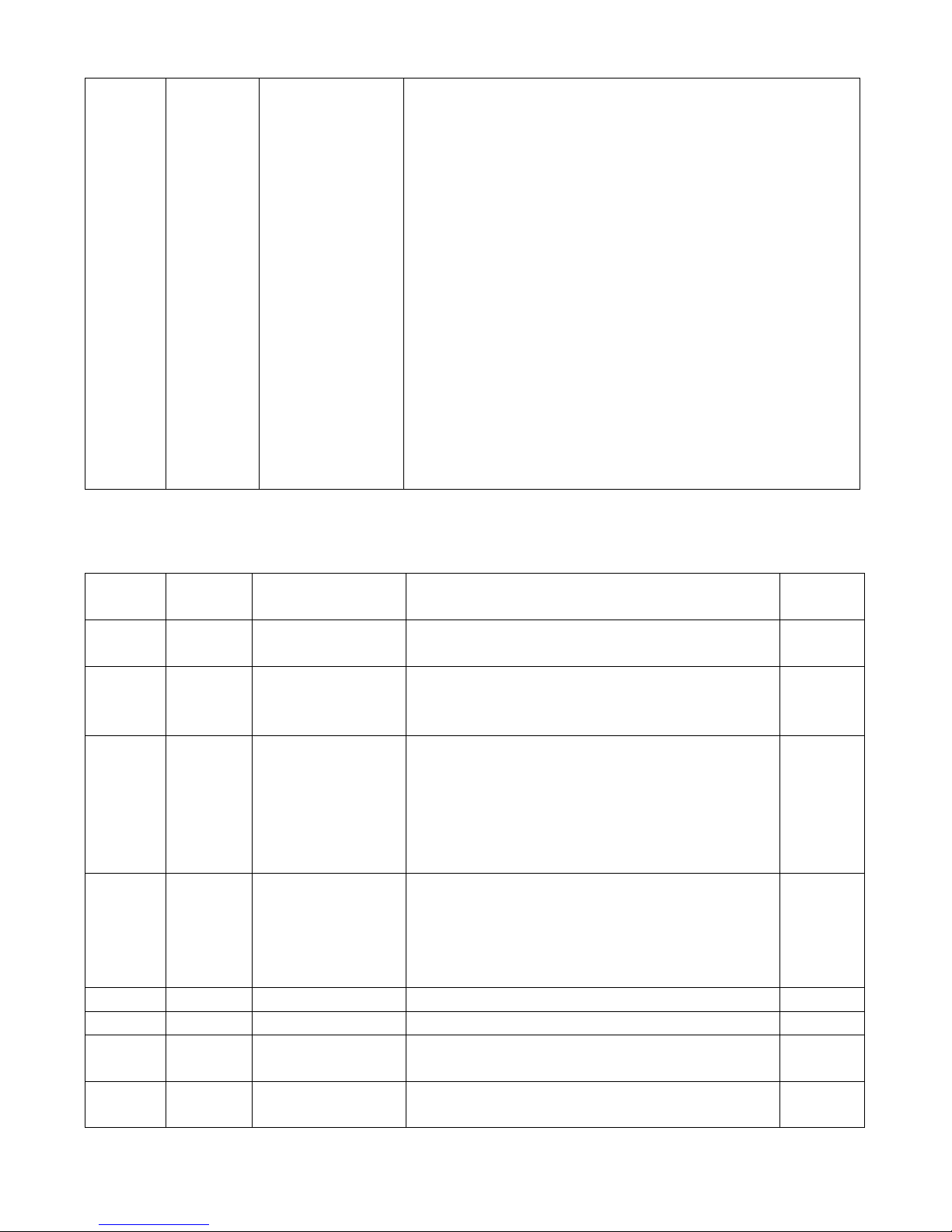
Parameter List: Group F005 (To Set Driver Parameters)
Numeric
Display
Internal
Address
Variable Name
Meaning
Default
Value
d5.00
2FF00108
Store_Loop_Data
1: Stores all setup parameters except motors
10: Initializes all setup parameters except motors
0
d5.01
100B0008
ID_Com
Station No. of Drivers
Note: To change this parameter, you need to save it
with the address ―d5.00‖, and restarts it later.
1
d5.02
2FE0001
0
RS232_Bandrate
Sets the baud rate of a serial port
540 19200
270 38400
90 115200
Note: To change this parameter, you need to save it
with the address ―d5.00‖, and restarts it later.
270
d5.03
2FE1001
0
U2BRG
Sets the baud rate of the serial port
540 19200
270 38400
90 115200
You need not restart it
270
d5.04
60F70110
Chop_Resistor
Indicates the values of braking resistors
0
d5.05
60F70210
Chop_Power_Rated
Indicates the nominal power of a braking resistor
0
d5.06
60F70310
Chop_Filter
Indicates the time constant of a braking resistor
Time: N*256/1000 Unit: S
60
d5.07
25010110
ADC_Shift_U
Indicates data configuration of U phase shift
Note:Factory parameters
N/A
Page 35
35
d5.08
25010210
ADC_Shift_V
Indicates data configuration of V phase shift
Note:Factory parameters
N/A
d5.09
30000110
Voltage_200
ADC original data when DC bus voltage is 200 V
Note:Factory parameters
N/A
d5.10
30000210
Voltage_360
ADC original data when DC bus voltage is 360 V
Note:Factory parameters
N/A
d5.11
60F60610
Comm_Shift_UVW
Indicates the excitation pointer of a motor
Note:Factory parameters
N/A
d5.12
26000010
Error_Mask
Indicates error masks
Note:Factory parameters
FFF.F
d5.13
60F70510
RELAY_Time
Indicates the relay operating time of capacitor
short-circuits
Unit: mS
Note:Factory parameters
150
d5.14
2FF00408
Key_Address_F001
Sets numeric display data
N/A
Chapter 6 Operation on Input/Output Ports
KINCO CD servo driver has 7 digital input ports (a digital input port can receive high-level or low-level
signals, depending on whether high-level or low-level signals are chosen at the COM terminal) and 5 digital
output ports (the OUT1-OUT4 ports can drive 100 mA load, and OUT5 port can drive 800 mA load, and can
directly drive the internal contracting brake device). You can freely configure all functions on digital
input/output ports according to application requirements.
6.1 Digital Input Signals
6.1.1 Polarity Control on Digital Input Signals
Table 6-1: Simplified IO polarity setting variables
Numeric
Display
Variable Name
Meaning
Default Value
Range
d3.08
Dio_Polarity
Sets IO polarity
0
N/A
Page 36
36
Table 6-2 Polarity setting methods for digital input signals
①
②
③
④
Input/output port
selection
0: Output port
1: Input port
Channel
selection
Input: 1-7
Output:
1-5
Reserved
0: The input port is valid when no current passes the
port, and the output port is valid when the switch tube
is open..
1: The input port is valid when the current passes the
port, and the output port is valid when the switch tube
is closed.
Other: Check the current status
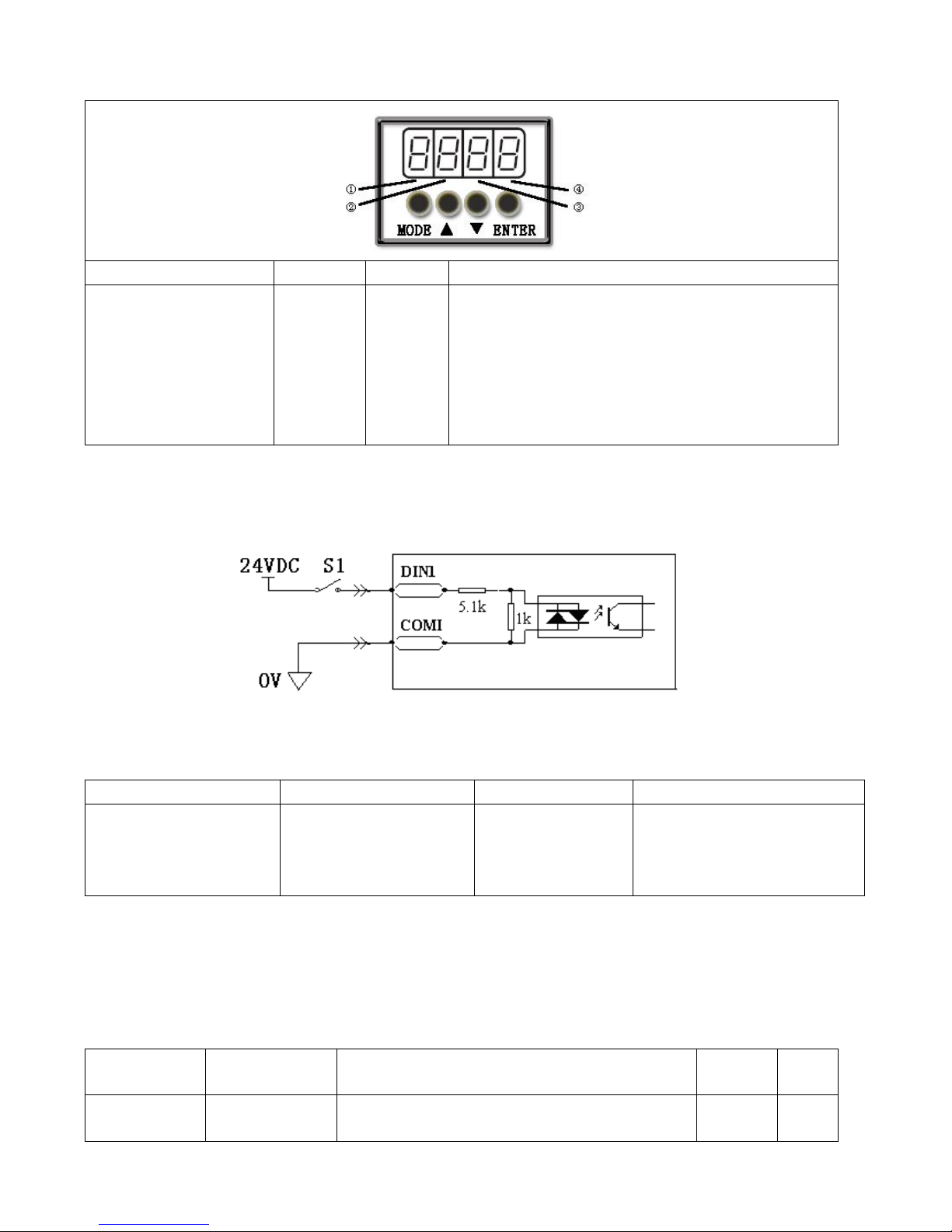
Example 6-1: Polarity Setting for Digital Input Signal DIN1
Fig. 6-1 Polarity setting for digital input signal DIN1
Table 6-3 Polarity setting for digital input signal DIN1
①
② ③ ④
Input/output port selection
Set to 1 (input port
selected)
Channel selection
Set to 1 (DIN 1 selected)
Reserved
0: D1N1 is enabled when S1
opens
1: D1N1 is enabled when S1
closes
Namely, if d3.08 is set to ―110.0‖, it indicates that DIN1 is enabled when no current passes the input port; if
d3.08 is set to ―110.1‖, it indicates that DIN1 is enabled when any current passes the input port.
6.1.2 Simulation of Digital Input Signals
Table 6-4 IO simulation variable
Numeric
Display
Variable Name
Meaning
Default
Value
Rang
e
d3.09
Dio_Simulate
Simulates input signals, and enforces output
signals for outputting
0
N/A
Page 37
37
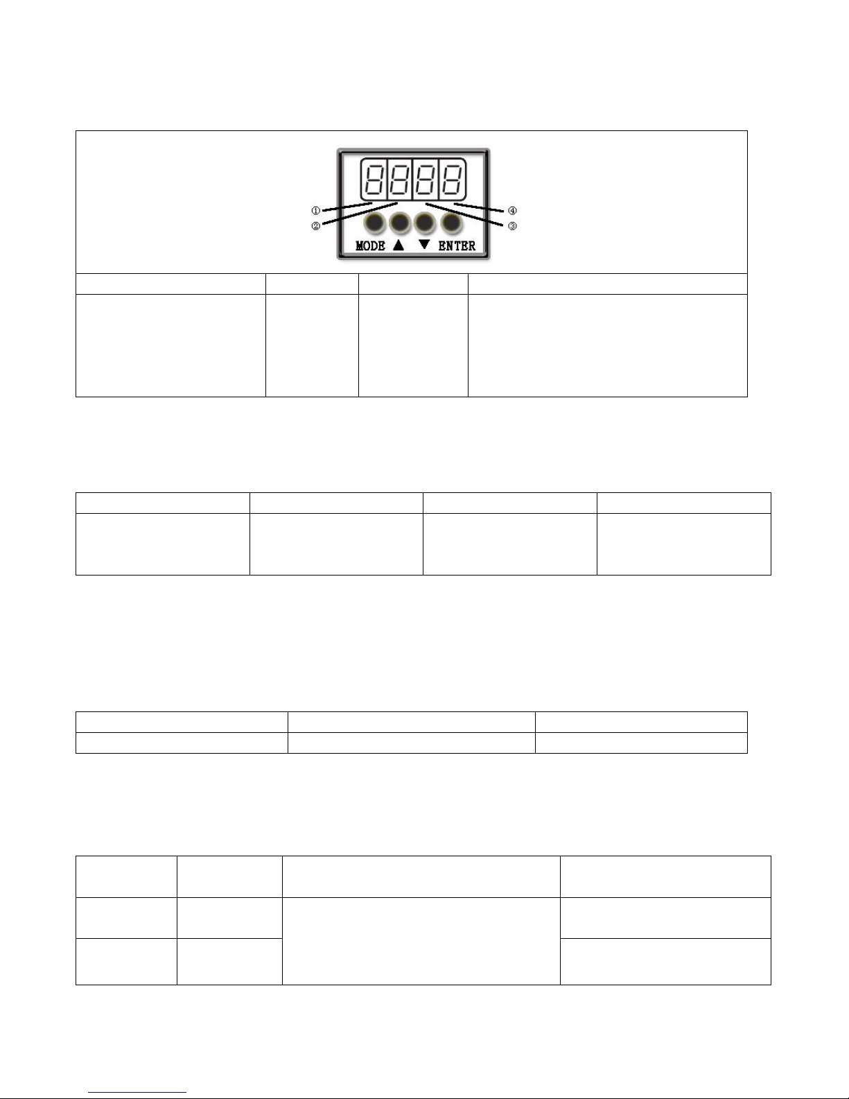
Dio_Simulate (IO simulation) is for the software to simulate inputting of a valid signal. ―1‖ indicates that
the input signal is valid, and ―0‖ indicates that the input signal is invalid.
Table 6-5 Settings on simulation of digital input signals
①
②
③
④
Input/output port selection
0: output port
1: input port
Channel
selection
Input: 1-7
Output: 1-5
Reserved
0: No input signal is simulated, and no
output signal is compulsorily outputted
1: Input signal is simulated, and output
signal is outputted compulsorily
Other: Check the current status
Example 6-2: Simulate digital input DIN1
Table 6-6: Simulate digital input DIN1
① ② ③
④
Input/output port selection
Set to 1 (input port
selected)
Channel selection
Set to 1 (DIN 1 selected)
Reserved
0: Invalid DIN1 simulation
1: Valid DIN1 simulation
Namely, if d3.09 is set to ―110.0‖, it indicates that no DIN1 input signals are simulated; if d3.09 is set to ―110.1‖,
it indicates that DIN1 input signals are simulated.
6.1.3 Status Display of Digital Input Signals
Table 6-7 Variables for status display of digital input signals
Numeric Display
Variable Name
Meaning
d1.11
Din_Status
Status of input ports
Din_Status (hexadecimal) is used to display the status of the actually input external signals in real time.
6.1.4 Addresses & Functions of Digital Input Signals
Table 6-8 Addresses & default functions of digital input signals
Numeric
Display
Variable
Name
Meaning
Default Value
d3.01
Din1_Function
000.0: Disable
000.1: Driver enable
000.2: Driver fault reset
000.4: Operation mode control
000.1 (Driver enable)
d3.02
Din2_Function
000.2 (Driver fault reset)
Page 38
38
d3.03
Din3_Function
000.8: P control for velocity loop
001.0: Position positive limit
002.0: Position negative limit
004.0: Homing signal
008.0: Reverse speed demand
010.0: Internal speed control 0
020.0: Internal speed control 1
040.0: Internal position control 0
080.0: Internal position control 1
100.0: Quick stop
200.0:Start homing
400.0:Activate command
000.4 (Operation mode control)
d3.04
Din4_Function
000.8 (P control for velocity
loop)
d3.05
Din5_Function
001.0 (Position positive limit)
d3.06
Din6_Function
002.0 (Position negative limit)
d3.07
Din7_Function
004.0 (Homing signal)
Note:DinX_Function (X ranges from 1 to 7) is used to define the functions of digital input ports. User can
freely define the functions of the digital input ports according to actual applications.
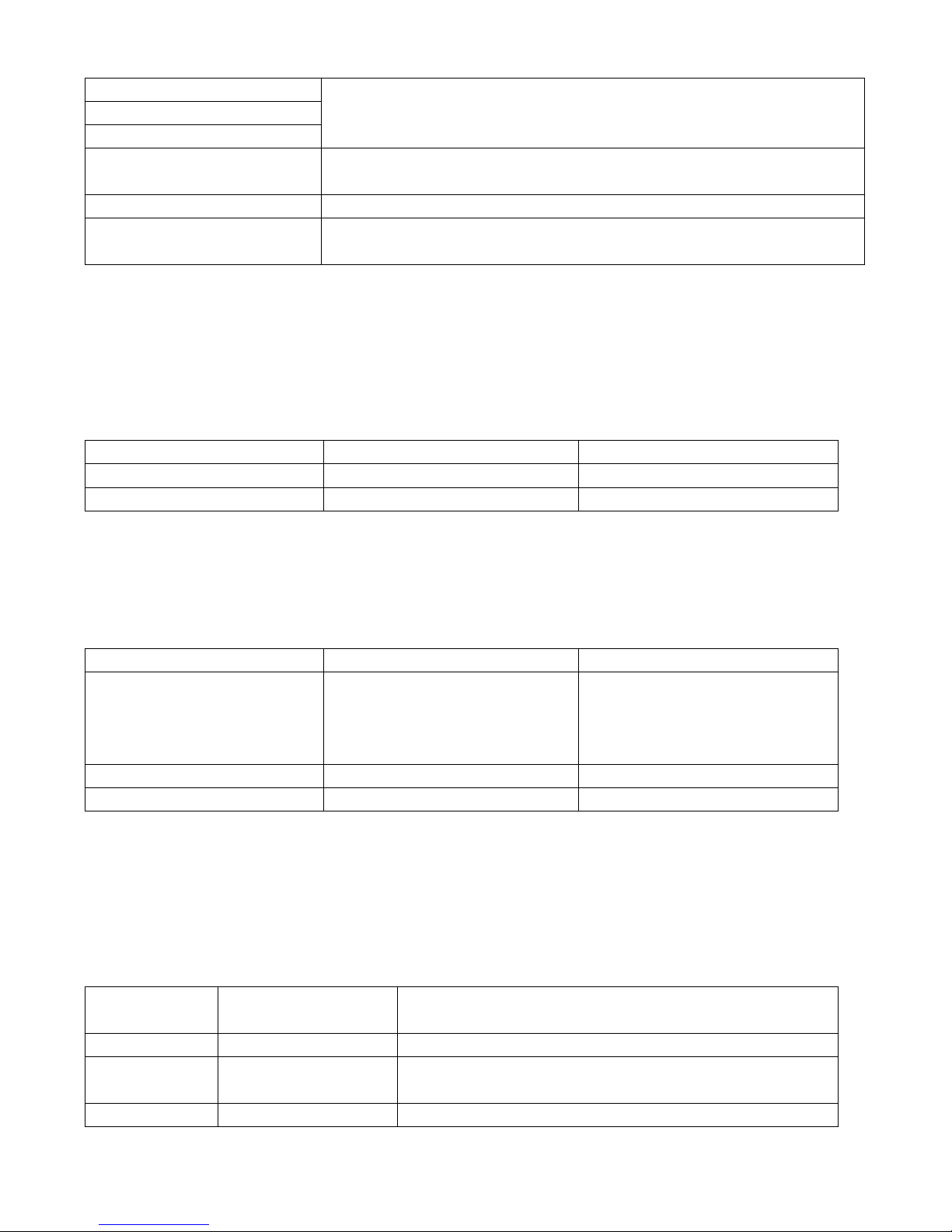
Table 6-9 Meaning of defined functions of digital input signals
Function
Meaning
Disable
Used to cancel the function of this digital input.
Driver enable
By default, the driver enable signal is valid, and the motor shaft is locked.
Driver fault reset
Signals on the rising edge are valid, and alarms are cleared.
Operation mode control
To switch between two operation modes.
You can freely determine the operation modes corresponding to valid signals
and invalid signals by performing settings through d3.16 Din_Mode0 (choose
0 for operation mode) of Group F003 and Din_Mode1 (choose 1 for operation
mode) of Group F003.
P control for velocity loop
Indicates the control on stopping integration in velocity loop. The control is
applied in the occasion where high-speed system stop occurs, but
overshooting is not expected.
Note: In the ―-3‖ mode, if the signal is valid, fixed errors occur between the
actual speed and target speed.
Position positive limit
Indicates the limit of forward running of motors (normally closed contact by
default).
By default, the driver regards position positive limits as valid, and polarity can
be modified to adjust to normally open switches.
Position negative limit
Indicates the limit of inverted running of motors (normally closed contact by
default).
By default, the driver regards position negative limits as valid, and polarity can
be modified to adjust to normally open switches.
Homing signal
To find origins of motors.
Reverse speed demand
To reverse the target speed in the speed mode ("-3" or ―3‖).
Internal speed control 0
To control internal multiple speeds.
Note: For details, see Section 7.5 Internal Multi-Speed Control.
Internal speed control 1
Internal speed control 2
Page 39
39
Internal position control 0
To control internal multiple positions.
Note: For details, see Section 7.4 Internal Multi-Position Control.
Internal position control 1
Internal position control 2
Quick stop
When the signal is valid, the motor shaft releases.
After the signal is removed, the driver requires re-enabling.
Start homing
When the rising edge of the signal is detected,it will start homing command.
Activate command
When the rising edge of the signal is detected,it will activate the internal
position control
Example 6-3: Driver Enable Setting
Requirement: The ―driver enable‖ function is controlled through an external digital output port. In this
example, the digital input port DIN1 is defined as the ―driver enable‖ function. Table 6-10 shows the setup
method.
Table 6-10 Digital Input Port DIN1 Defined as the ―Driver Enable‖ Function
Numeric Display
Variable Name
Parameter Settings
d3.01
Din1_Function
Set to 000.1
d3.00
Store_Loop_Data
Set to 1
Note: Any digital output of DIN1-7 can be defined as ―driver enable‖, and is set to 000.1, that is, bit 0 is valid.
Requirement: Enable the function of automatically powering on the driver by setting internal parameters
in drivers instead of external digital input ports. Table 6-11 describes the setup method.
Table 6-11 Enabling the function of automatically powering on the driver by setting internal parameters in
drivers
Numeric Display
Variable Name
Parameter Settings
d3.01- d3.07
DinX_ Function
(1~7)
None of the digital input port can be
set to 000.1, that is, the Enable
function is not controlled by any
digital input port.
d3.10
Switch_On_Auto
Set to 1
d3.00
Store_Loop_Data
Set to 1
Example 6-4: Disabling Position Positive/Negative Limit Settings
When the driver is delivered, the DIN5 of the motor is the position positive limit and DIN6 is the position
negative limit by default. If there are no external position positive/negative limit switches, this function must be
disabled so that the servo driver can work properly. Table 6-12 describes the setup method.
Table 6-12: Disabling position positive/negative limit settings
Numeric
Display
Variable Name
Parameter Settings
d3.05
Din5_Function
Change the default value 001.0 (position positive limit) to 000.0
d3.06
Din6_Function
Change the default value 002.0 (position negative limit) to
000.0
d3.00
Store_Loop_Data
Set to 1
Page 40
40
Example 6-5: Operation Mode Control on Drivers
Requirements: Defines the input port DIN3 as the operation mode control on drivers, and the operation
mode is ―-4‖ (pulse control mode) when DIN3 fails, and is ―-3‖ (instantaneous speed mode) when DIN3 is
valid. Table 6-13 describes the setup method.
Table 6-13 Settings on operation mode control on drivers
Numeric Display
Variable Name
Parameter Settings
d3.03
Din3_Function
Set to 000.4
d3.16
Din_Mode0
Set to 0.004 (-4)
d3.17
Din_Mode1
Set to 0.003 (-3)
d3.00
Store_Loop_Data
Set to 1
Note: If the driver is required to operate in some mode with power on, one of the digital input must be set as
function ―Operation Mode Control‖. Then you can set the operation modes that require in the parameters
d3.16 or d3.37 in Group F003.
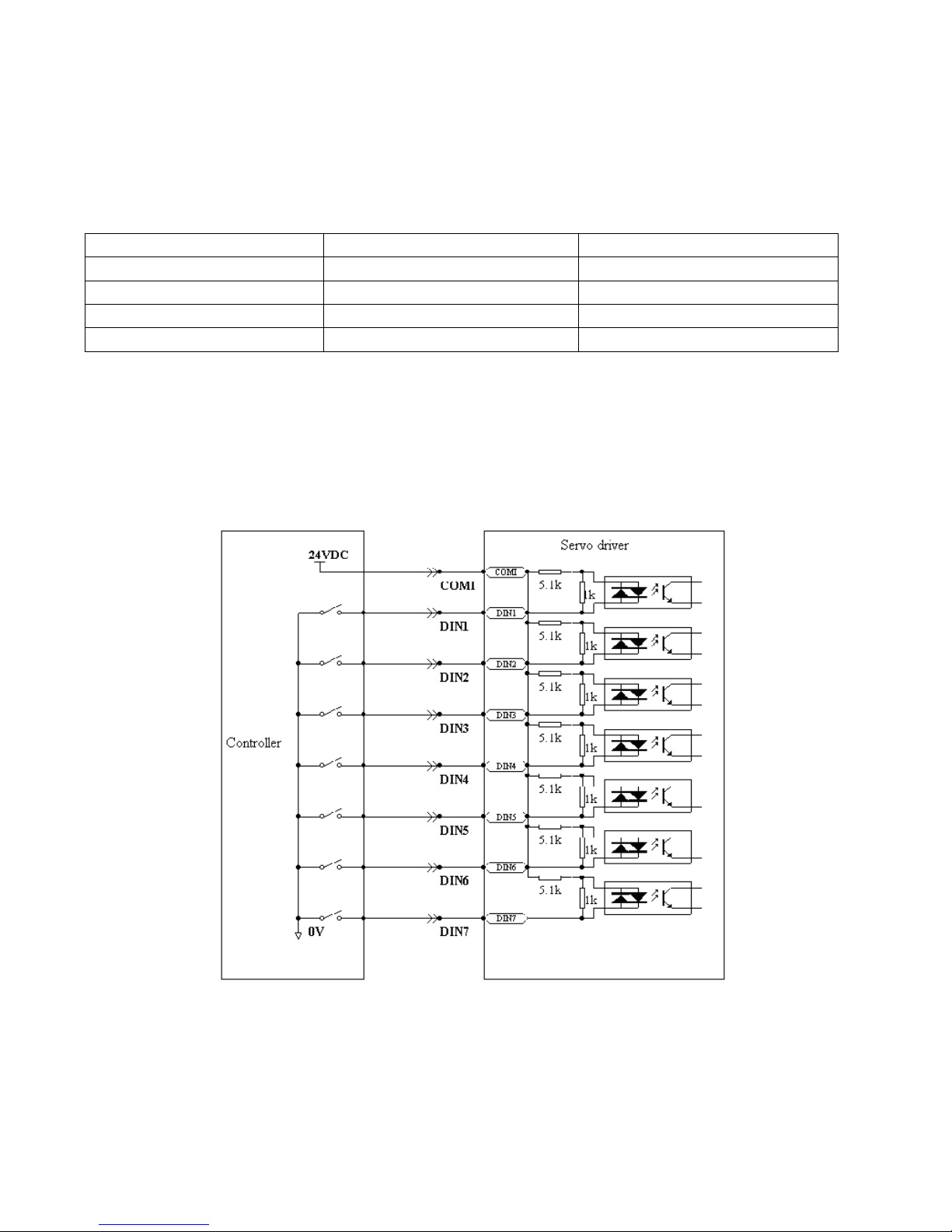
6.1.5 Wirings of Digital Input Port
1. NPN wiring diagram (to the controller that supports low level output)
Fig. 6-2 NPN wiring diagram (to the controller that supports low level output)
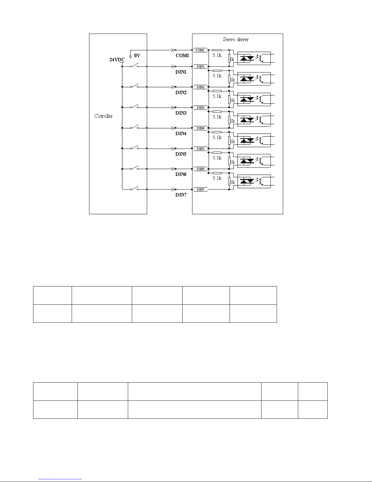
2. PNP wiring diagram (to the controller that supports high level output)
Page 41
41
Fig. 6-3 PNP wiring diagram (to the controller that supports high level output)
6.2 Digital Output Signals
6.2.1 Polarity Control on Digital Output Signals
Table 6-14 Variables for setting simplified IO polarity
Numeric
Display
Variable Name
Meaning
Default
Value
Range
d3.08
Dio_Polarity
Sets IO polarity
0
N/A
Dio_Polarity (simplified IO polarity settings) is used to set the polarity of valid digital output signals. The
number ―1‖ indicates normally open, and ―0‖ indicates normally close.Default is 1.
6.2.2 Simulation of Digital Output Signals
Table 6-15 IO simulation variables
Numeric
Display
Variable Name
Meaning
Default
Value
Range
d3.09
Dio_Simulate
Simulates input signals, and the output signal is
outputted compulsorily
0
N/A
Dio_Simulate (IO simulation) is to simulate the output of a valid signal. The number ―1‖ indicates that the
output signal is valid, and ―0‖ indicates that the output signal is invalid.
Page 42
42
6.2.3 Status Display of Digital Output Signals
Table 6-16 Variables for status display of digital output signals
Numeric Display
Variable Name
Meaning
d1.12
Dout_Status
Status of an output port
Din_Status (hexadecimal) displays the status of actual external output signals in real time.
6.2.4 Addresses and Functions of Digital Output Signals
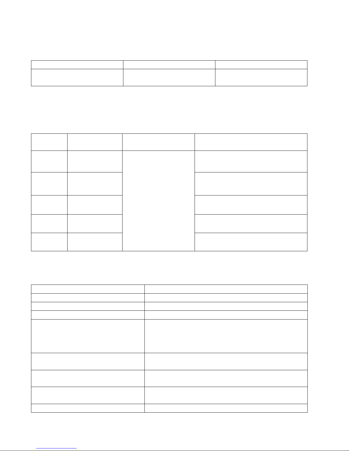
Table 6-17 Addresses and default functions of digital output signals
Numeric
Display
Variable Name
Meaning
Default Value
d3.11
Dout1_Function
000.0: Disable
000.1: Ready
000.2: Error
000.4: Position reached
000.8: Zero velocity
001.0: Motor brake
002.0: Velocity reached
004.0: Index
008.0: Max. velocity limit
010.0: PWM ON
020.0:Motor limiting
040.0:Reference found
000.1 (Ready)
d3.12
Dout2_Function
000.2 (Error)
d3.13
Dout3_Function
00a.4 (Position reached/Velocity
reached/Max. velocity limit)
d3.14
Dout4_Function
000.8 (Zero velocity)
d3.15
Dout5_Function
001.0 (Motor brake)
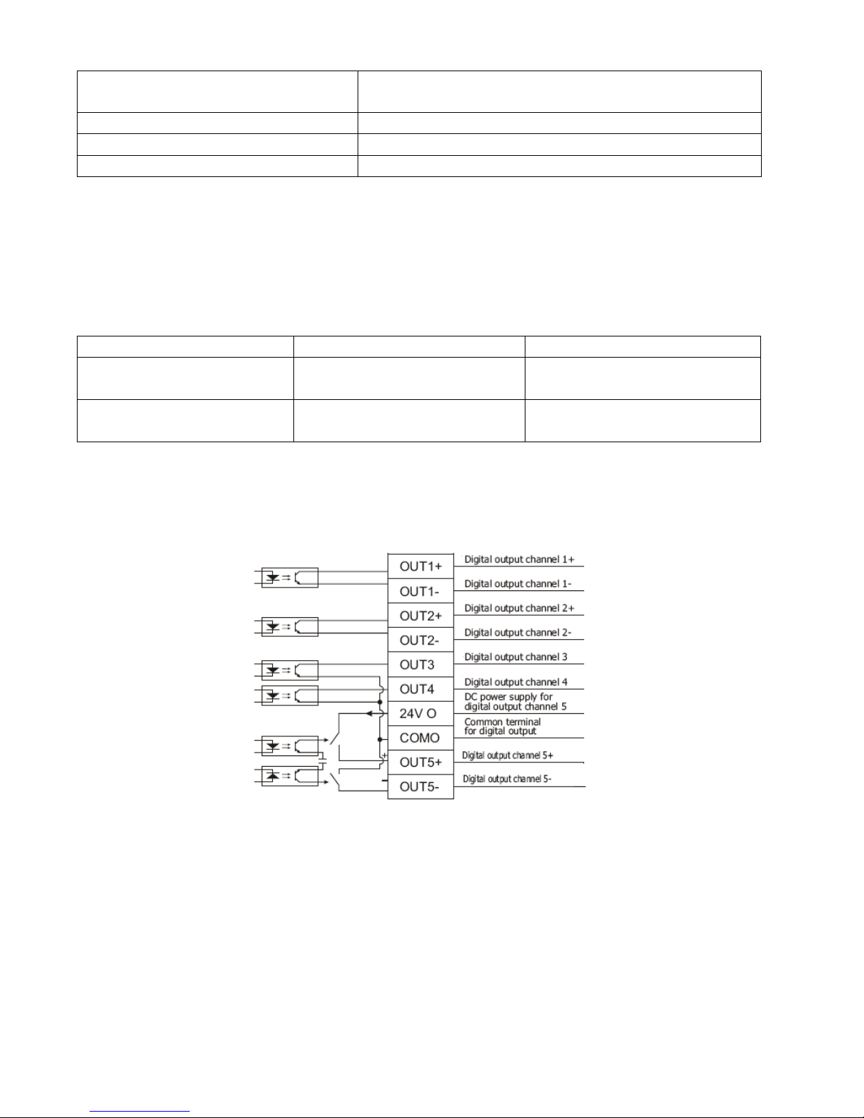
DinX_Function (X ranges from 1 to 5) is used to define the functions of digital output ports. User can
freely define the functions of digital output ports according to actual applications.
Table 6-18 Meanings of the functions defined by digital output signals
Function
Meaning
Disable
Cancel the function of this digital output
Ready
The driver is ready for operation.
Error
Alarm signals are output, indicating that the driver is faulty.
Position reached
In the ―-4‖ mode of pulse control, the target position data keeps
unchanged in the window (d3.39) of the time of reaching the
target position, and position errors are within the window of
reaching the target position.
Zero velocity
After the motor is enabled, it is outputted when the motor speed
is 0.
Motor brake
The driver enables the motor, and contracting brake output is
valid.
Velocity reached
In the ―-3‖ or "3‖ internal speed control mode, signals are output
after they reach the target speed.
Index
Z phase signal output (the speed should not be too high).
Page 43
43
Max. velocity limit
In the ―4‖ analog – torque mode, signals are output after the
max restricted speed is reached.
PWM ON
The driver enables the motor.
Motor limiting
Motor is in the status of position limiting.
Reference found
Homing is finished.
Example 6-6: “Ready” settings
Requirement: The digital output port 1 is defined as the ―Ready‖ function. For details on settings, see
Table 6-23.
Table 6-19: ―Ready‖ settings
Numeric Display
Variable Name
Parameter Settings
d3.11
Dout1_Function
Set to 000.1
d3.00
Store_Loop_Data
Set to 1
6.2.5 Wiring of Digital Output Port
1. Internal circuit diagram of digital output ports
Fig. 6-4 Internal circuit diagram of digital output ports
Note: To apply the OUT3 or OUT4 port, the COMO port must be connected. To apply the OUT5 port, both the
24VO and COMO ports must connect to the external input power.
2. NPN wiring (to controllers that support valid low level input)
Page 44
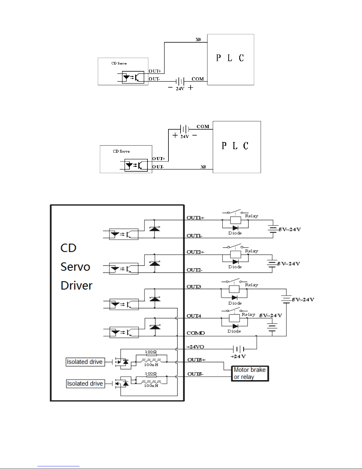
44
Fig. 6-5 NPN wiring diagram (to controllers that support valid low level input)
3. PNP wiring (to controllers that support valid low level input)
Fig. 6-6 PNP wiring diagram (to controllers that support valid low level input)
4. To connect a relay to the digital output port, do remember to connect a diode in inverse parallel, as
shown in Fig. 6-7.
Fig. 6-7 Connect a relay to the digital output port
Page 45
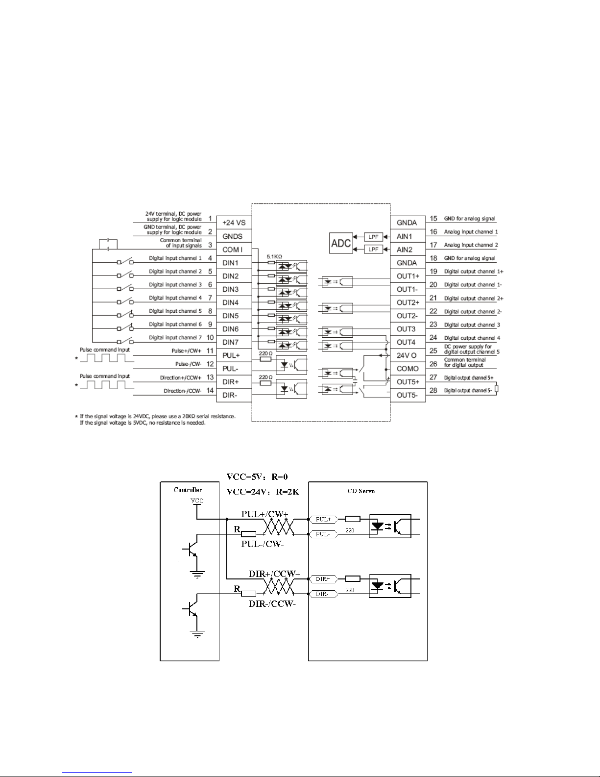
45
Chapter 7 Mode Operation
7.1 Pulse Control Mode (“-4” Mode)
7.1.1 Wiring in Pulse Control Mode
1. Interfaces in pulse control mode
Fig. 7-1 Interface in pulse control pattern
2. Common anode connection (to controllers that support valid low level output)
Fig. 7-2 Common anode connection (to controllers that support valid low level output)
3. Common cathode connection (to controllers that support valid high level output)
Page 46
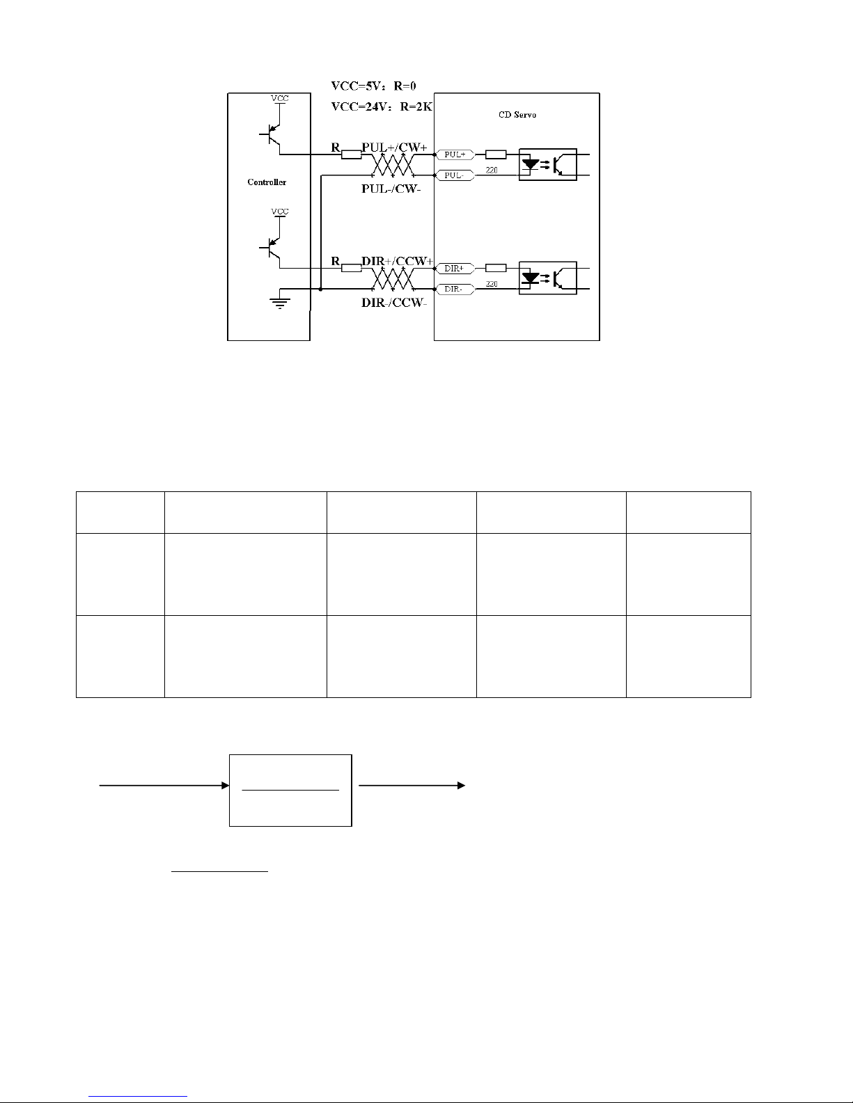
46
Fig. 7-3 Common cathode connection (to controllers that support valid high level output)
7.1.2 Parameters for Pulse Control Mode
1. Parameters for electronic gear ratio
Table 7-1 Parameters for electronic gear ratio
Numeric
Display
Variable Name
Meaning
Default Value
Range
d3.34
Gear_Factor
Indicates the
numerator to set
electronic gears in the
―-4‖ operation mode
1000
-32767~32767
d3.35
Gear_Divider
Indicates the
denominator to set
electronic gears in the
―-4‖ operation mode
1000
1~32767
Parameters for electronic gear ratio are used to set the numerator and denominator of electronic gears when
the driver operates in the ―-4‖ mode.
Command pulse input Command pulse output
F1 F2
Namely: F2=
DividerGear
FactorGear__
* F1
If the electronic gear ratio is 1:1, 10000 pulses are inputted externally (the resolution of encoders is 2500
PPR, quadruple), and the motor turns a circle. If the electronic gear ratio is 2:1, 10000 pulses are inputted
externally, and the motor turns two circles.
2. Parameters for pulse mode selection
Table 7-2 Parameters for pulse mode selection
DividerGear
FactorGear__
Page 47
47
Numeric
Display
Variable Name
Meaning
Default
Value
Range
d3.36
PD_CW
0: Double pulse (CW/CCW) mode
1. Pulse direction (P/D) mode
Note: To change this parameter, you
need to save it with d3.00, and restarts it
later.
1 N/A
Note: AB phase signals are not supported.
Double pulse (CW/CCW) mode (d3.36 = 0)
Pulse direction (P/D) mode (d3.36 = 1)
3. Parameters for pulse filtering coefficient
Table 7-3 Parameters for pulse filtering coefficient
Numeric
Display
Variable
Name
Meaning
Default
Value
Range
d3.37
PD_Filter
Used to smooth the input pulses.
Filter frequency: f = 1000/(2π* PD_Filter)
Time constant: T = PD_Filter/1000
Unit: S
Note: If you adjust this parameter during the operation,
some pulses may be lost.
3
1~3276
7
When a driver operates in the pulse control mode, if the electronic gear ratio is set too high, it is required
to adjust this parameter to reduce motor oscillation; however, if the parameter adjustment is too great, motor
running instructions will become slower.
4. Parameters for pulse frequency control
Table 7-4 Parameters for pulse frequency control
Numeric Display
Variable Name
Meaning
Default
Value
Range
d3.38
Frequency_Check
Indicates the limitation on pulse input
frequency (kHz)
600
0~600
5. Parameters for gain control on position loops and velocity loops
Forward rotation
Reverse rotation
Forward rotation
Reverse rotation
Effective on the
rising edge
Effective on the
rising edge
Page 48
48
Current loops are related to motor parameters (optimal parameters of the selected motor are default for
the driver and no adjusting is required).
Parameters for velocity loops and position loops should be adjusted properly according to loading
conditions.
During adjustment of the control loop, ensure that the bandwidth of the velocity loop is at least twice of
that of the position loop; otherwise oscillation may occur.
Table 7-5 Parameters for gain control on position loops
Numeric
Display
Variable Name
Meaning
Default
Value
Range
d2.07
Kpp
Indicates the proportional gain of the
position loop Kpp
1000
0~16384
d2.08
K_Velocity_FF
0 indicates no feedforward, and 256
indicates 100% feedforward
256
0~256
d2.09
K_Acc_FF
The value is inversely proportional to the
feedforward
32767
32767~10
d0.05
Pc_Loop_BW
Sets the bandwidth of the position loop in
Hz.
0
/
Proportional gains of the position loop Kpp: If the proportional gain of the position loops increases, the
bandwidth of the position loop is improved, thus reducing both the positioning time and following errors.
However, too great bandwidth may cause noise or even oscillation. Therefore, this parameter must be set
properly according to loading conditions. In the formula Kpp=103* Pc_Loop_BW,Pc_Loop_BW indicates the
bandwidth of the position loop. The bandwidth of a position loop is less than or equal to that of a velocity loop.
It is recommended that Pc_Loop_BW be less than Vc_Loop_BW /4 (Vc_Loop_BW indicates the bandwidth of
a velocity loop).
Velocity feedforward of the position loop K_Velocity_FF : the velocity feedforward of a position loop can be
increased to reduce position following errors. When position signals are not smooth, if the velocity
feedforward of a position loop is reduced, motor oscillation during running can be reduced. Acceleration
feedback of the position loop K_Acc_FF (adjustment is not recommended for this parameter): If great gains of
position loops are required, the acceleration feedback K_Acc_FF can be properly adjusted to improve
performance.
* * _
K_Acc_FF
250000* 2* *
pt
t
I K Encoder R
J
Note: K_Acc_FF is inversely proportional to the acceleration
feedforward.
Table 7-6 Parameters for gain control on position loops
Numeric
Display
Variable Name
Meaning
Default
Value
Range
d2.01
Kvp Sets the response speed of a velocity loop
100
0~3276
7
d2.02
Kvi Adjusts speed control so that the time of minor
errors is compensated
2
0~1638
4
d2.05
Speed_Fb_N
You can reduce the noise during motor operation
by reducing the feedback bandwidth of velocity
loops (smoothing feedback signals of encoders).
45
0~45
Page 49

49
When the set bandwidth becomes smaller, the
motor responds slower. The formula is
F=Speed_Fb_N*20+100.
For example, to set the filter bandwidth to "F = 500
Hz‖, the parameter should be set to 20.
Proportional gain of velocity loop Kvp: If the proportional gain of the velocity loop increases, the responsive
bandwidth of the velocity loop also increases. The bandwidth of the velocity loop is directly proportional to the
speed of response. Motor noise also increases when the velocity loop gain increases. If the gain is too great,
system oscillation may occur.
Integral gain of velocity loop Kvi: If the integral gain of the velocity loop increases, the low-frequency intensity
is improved, and the time for steady state adjustment is reduced; however, if the integral gain is too great,
system oscillation may occur.
7.1.3 Examples of Pulse Control Mode
In the pulse control mode, follow the steps below to configure a driver:
Step 1: Confirm whether the functions of the driver require enabling through external digital input ports. To
enable the driver through external digital input ports, see Table 6-12 in Example 6-3 for settings. If it is not
necessary to enable the driver through external digital input ports, you can disable the enabling control
function of external digital input ports by referring to Table 6-13 of Example 6-3, and enable the driver by
setting its internal parameters.
Step 2: Confirm whether limit switches are required. By default, the driver operates in the limit status after
being powered on. In this case, the numeric display has limit status display. If there is no limit switches,
please disable the function of limit switches by referring to Example 6-4.
Step 3: Confirm mode switching bits and operation modes by referring to the settings in Example 6-5. The
factory default settings of the driver are as follows: When no signal is inputted on DIN3, the driver operates in
the ―-4‖ mode (pulse control mode).
Step 4: After function configuration on digital input ports, it is required to set parameters such as pulse modes
and electronic gear ratio.
Step 5: Save parameters.
Example 7-1: Pulse control mode “-4” – enable the driver through external
digital input
Requirement: DIN1 is used for enabling the driver, DIN2 is used for error resetting, and DIN3 controls the
operation modes of the driver (the mode is ―-4‖ when no signal is inputted, and the mode is ―-3‖ when signal is
inputted). Limit switches are unavailable. The pulse form is pulse/direction, and the electronic rear ratio is 2:1.
Table 7-7 describes the setup method.
Table 7-7: Pulse control mode ―-4‖ – enable the driver through external digital input
Numeric
Display
Variable Name
Meaning
Parameter Settings
d3.01
Din1_Function
Defines the functions of digital input
port 1
000.1 (Driver enable)
d3.02
Din2_Function
Defines the functions of digital input
000.2 (Fault reset)
Page 50
50
port 2
d3.03
Din3_Function
Defines the functions of digital input
port 3
000.4 (Operation mode
control )
d3.05
Din5_Function
Defines the functions of digital input
port 5
The default value 001.0
changes to 000.0 (position
positive limits are disabled)
d3.06
Din6_Function
Defines the functions of digital input
port 6
The default value 002.0
changes to 000.0 (position
negative limits are disabled)
d3.16
Din_Mode0
Select this operation mode when
input signals are invalid
Set to 0.004 (-4) mode
(pulse control mode)
d3.17
Din_Mode1
Select this operation mode when
input signals are valid
Set to 0.003 (-3) mode
(instantaneous speed mode)
d3.34
Gear_Factor
Indicates the numerator to set
electronic gears in the ―-4‖ operation
mode (pulse control mode)
Set to 2000
d3.35
Gear_Divider
Indicates the denominator to set
electronic gears in the ―-4‖ operation
mode (pulse control mode)
Set to 1000
d3.36
PD_CW
0: Double pulse (CW/CCW) mode
1. Pulse direction (P/D) mode
Note: To change this parameter, you
need to save it with the address
―d3.00‖, and restarts it later.
Default value is 1
(pulse direction)
d3.00
Store_Loop_Data
1: Storing all configured parameters
for the control loop
10: Initializing all parameters for the
control loop
Set to 1
Example 7-2 Pulse control mode “-4” – enable the driver automatically after
driver power on
Requirement: The auto power-on function of the driver is enabled, DIN2 is used for error resetting, and DIN3
controls the operation modes of a driver (the mode is ―-4‖ when no signal is inputted, and the mode is ―3‖
when signal is inputted). Limit switches are unavailable. The pulse form is pulse/direction, and the electronic
rear ratio is 1:2. Table 7-8 describes the setup method.
Table 7-8 Pulse control mode ―-4‖ – enable driver automatically after driver power on
Numeric
Display
Variable Name
Meaning
Parameter Settings
d3.01d3.07
DinX_ Function
(1~7)
Defines the functions of digital input
ports 1-7
None of the digital input port
can be set to 000.1, that is, the
Enable function is not controlled
by any digital input port.
d3.02
Din2_Function
Defines the functions of digital input
000.2 (Error resetting)
Page 51
51
port 2
d3.03
Din3_Function
Defines the functions of digital input
port 3
000.4 (Control on operation
modes for the driver)
d3.05
Din5_Function
Defines the functions of digital input
port 5
The default value 001.0
changes to 000.0 (position
positive limits are disabled)
d3.06
Din6_Function
Defines the functions of digital input
port 6
The default value 002.0
changes to 000.0 (position
negative limits are disabled)
d3.10
Switch_On_Auto
0: No control
1:Automatically locks the motor when
the driver is powered on
Set to 1
d3.16
Din_Mode0
Select this operation mode when
input signals are invalid
Set to 0.004 (-4) mode
(pulse control mode)
d3.17
Din_Mode1
Select this operation mode when
input signals are valid
Set to 0.003 (-3) mode
(instantaneous speed mode)
d3.34
Gear_Factor
Indicates the numerator to set
electronic gears in the ―-4‖ operation
mode (pulse control mode)
Set to 1000
d3.35
Gear_Divider
Indicates the denominator to set
electronic gears in the ―-4‖ operation
mode (pulse control mode)
Set to 2000
d3.36
PD_CW
0: Double pulse (CW/CCW) mode
1. Pulse direction (P/D) mode
Note: To change this parameter, you
need to save it with the address
―d3.00‖, and restarts it later.
Default value is 1
(pulse direction)
d3.00
Store_Loop_Data
1: Storing all configured parameters
for the control loop
10: Initializing all parameters for the
control loop
Set to 1
7.2 Speed Mode (“-3” or “3” Mode)
In the instantaneous speed mode (―-3‖ mode), the actual speed reaches the target speed instantly. As a
contrast, in the speed mode with acceleration/deceleration (―3‖ mode), the actual speed gradually increases
until it reaches the target speed. Both the acceleration and deceleration (trapeziform shape) are configured
respectively by d2.10 and d2.11. In the ―3" mode, you can set Kpp to enable/disable position loops. If a
position loop is enabled, speed oscillation is less than that when the loop is disabled. If Kpp is 0, it indicates
that the position loop is closed.
Page 52
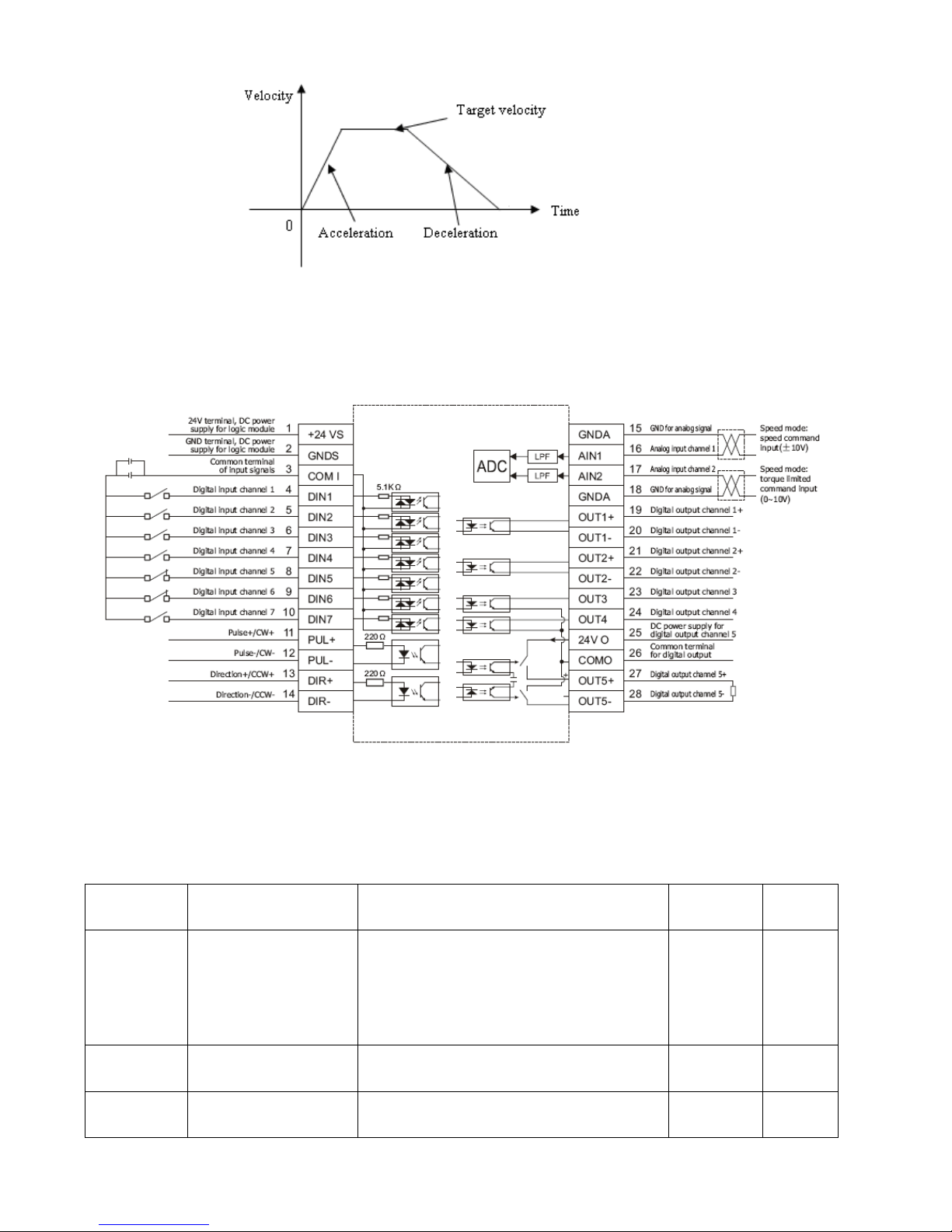
52
Fig. 7-4 The speed mode ―3‖ with acceleration/deceleration
7.2.1 Wiring in Analog – Speed Mode
Fig. 7-5 Interfaces in analog –speed mode
7.2.2 Parameters for Analog – Speed Mode
Table 7-9 Parameters for analog – speed mode
Numeric
Display
Variable Name
Meaning
Default
Value
Range
d3.22
Analog1_Filter
Used to smooth the input analog signals.
Filter frequency: f=4000/(2π*
Analog1_Filter)
Time Constant (T) = Analog1_Filter/4000
(S)
5
1~127
d3.23
Analog1_Dead
Sets dead zone data for external analog
signal 1
0
0~8192
d3.24
Analog1_Offset
Sets offset data for external analog signal 1
0
-8192~8
192
Page 53
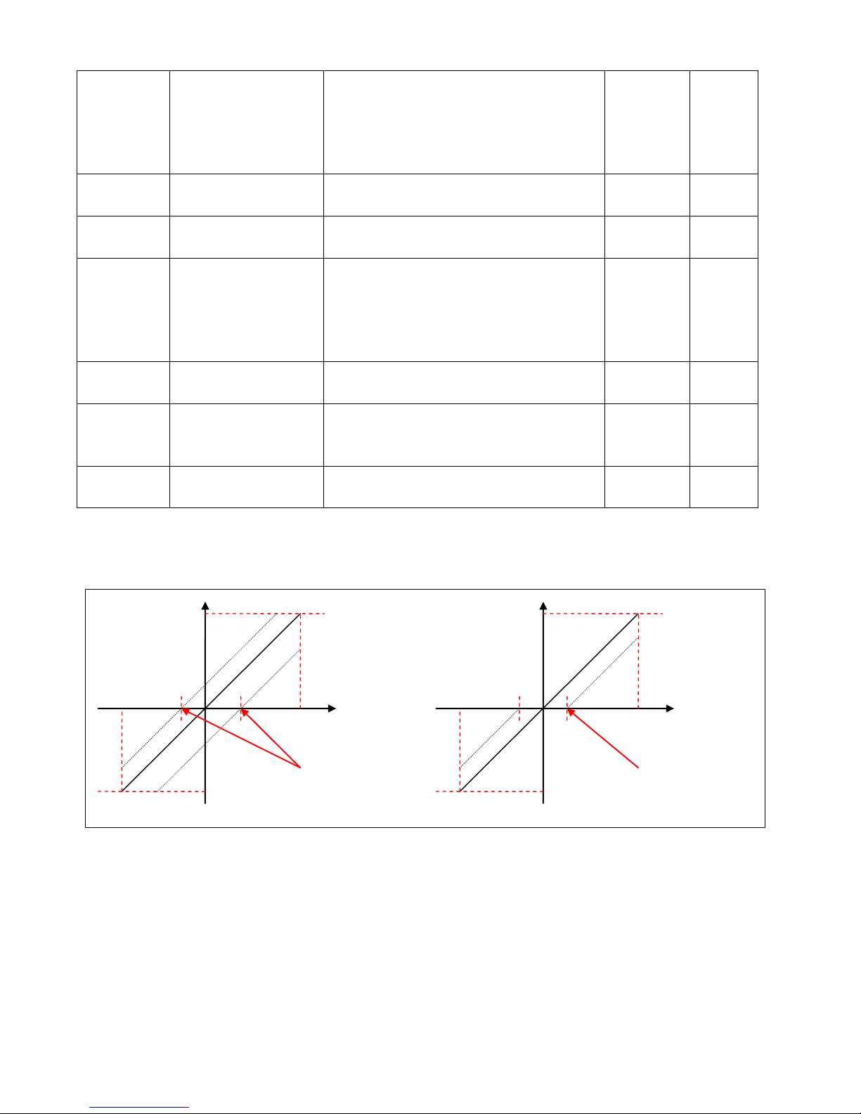
53
d3.25
Analog2_Filter
Used to smooth the input analog signals.
Filter frequency: f=4000/(2π*
Analog1_Filter)
Time Constant (T) = Analog2_Filter/4000
(S)
5
1~127
d3.26
Analog2_Dead
Sets dead zone data for external analog
signal 2
0
0~8192
d3.27
Analog2_Offset
Sets offset data for external analog signal 2
0
-8192~8
192
d3.28
Analog_Speed_Con
Selects analog-speed channels
0: Invalid analog channel
1: Valid analog channel 1 (AIN1)
2: Valid analog channel 2 (AIN2)
Valid mode -3 and mode 3
0
N/A
d3.29
Analog_Speed_Factor
Sets the proportion between analog signals
and output speed
1000
N/A
d3.32
Analog_MaxT_Con
0: No control
1: Max torque that Ain1 can control
2: Max torque that Ain2 can control
0
N/A
d3.33
Analog_MaxT_Factor
Indicates the max torque factor for analog
signal control
8192
N/A
7.2.3 Analog Signal Processing
Fig. 7-6 Analog signal processing
Electrical control on internal variables is available only after ADC conversion and offset of external analog
signals, and judgment of dead zone signals.
For offset processing, see the left part in Fig. 7-6; for dead zone processing, see the right part in Fig. 7-6.
Mathematical equation for offset processing:
shiftexternalernal
UUU
int
shift
U
dead
U
external
U
external
U
ernal
U
int ernal
U
int
Offset
Dead zone
Page 54
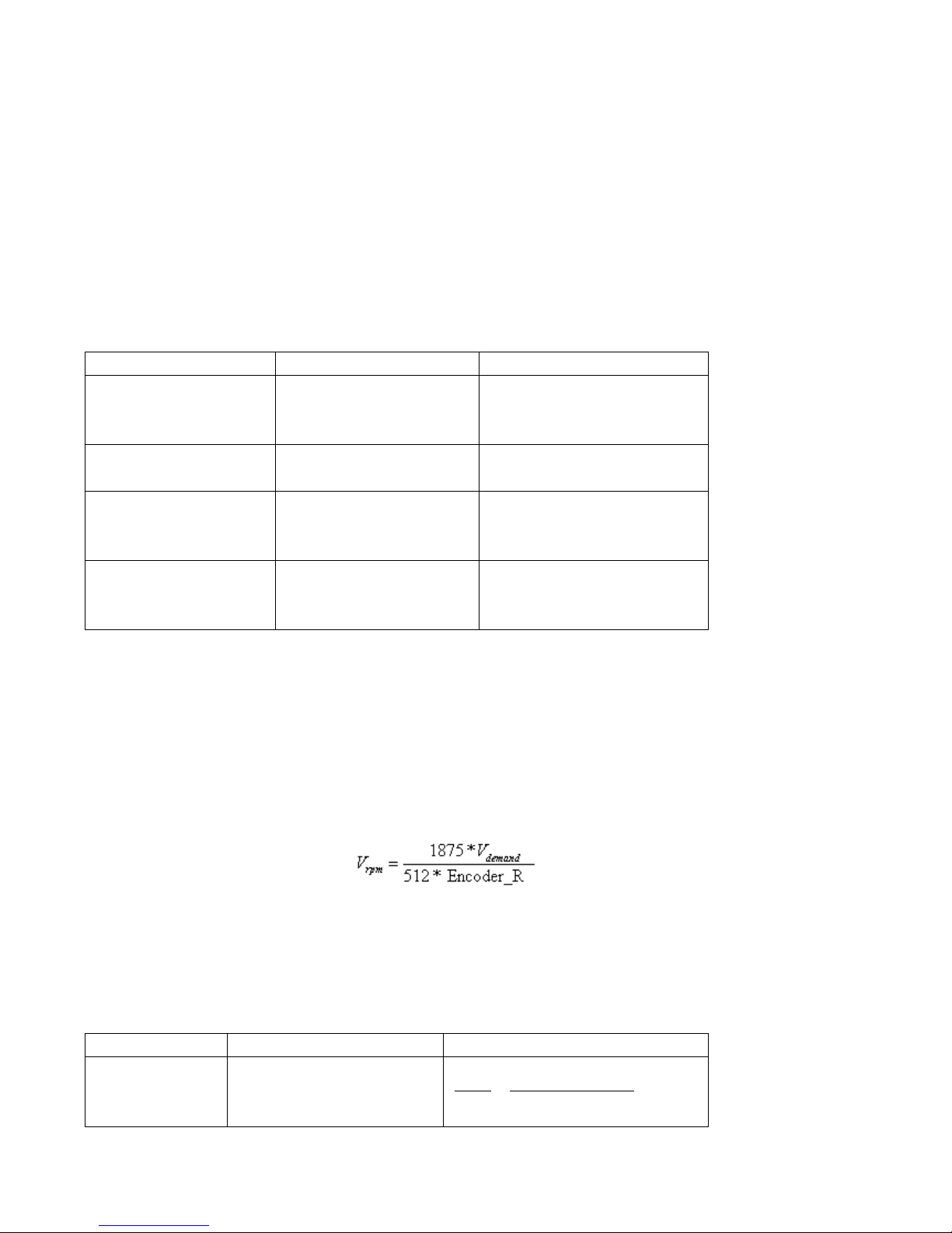
54
Mathematical equation for dead zone processing:
Mathematical equation for integrated processing (offset and dead zone)
Table 7-10 Analog signal variables
Variable
Meaning
Range
internal
U
Internal data corresponding
to the external voltage
-10 V – 10 V corresponds to
-2048 – 2047 when no offset or
dead zone voltage exists
tex ernal
U
External input voltage
-10V – 10V
shift
U
Offset voltage
0 – 10 V corresponds to
log_Ana Offset
0~8191
dead
U
Dead zone voltage
0 – 10 V corresponds to
log_Ana Dead
0~8191
The obtained analog signal
internal
U
obtains
filter
U
after passing through a first-order low-pass filter, and is
applied by the internal programs again.
In the analog – speed mode, if the analog signal
filter
U
that passes through the filter is multiplied by a factor,
this signal will be regarded as the internal target speed
demand
V
.
Mathematical formula:
Formula for
rpm
V
conversion:
Note: The resolution unit of an encoder is inc/r.
7.2.4 Calculation Procedure for Analog – speed Mode
Table 7-11 Calculation procedure for analog – speed mode
Procedure
Method
Formula
Step 1
Calculate
filter
U
according
to the offset voltage and dead
2047
10 10
filter
shift dead
U
v v U U
externaldead
externaldead
deadexternalernal
deadexternaldeadernal
UU
UU
UUU
UUUU
int
int
0
shiftexternaldead
shiftexternaldead
deadshiftexternalernal
deadshiftexternaldeadernal
UUU
UUU
UUUU
UUUUU
int
int
0
20472048*
filterfilterdemand
UUFactorV
demand
V
Page 55
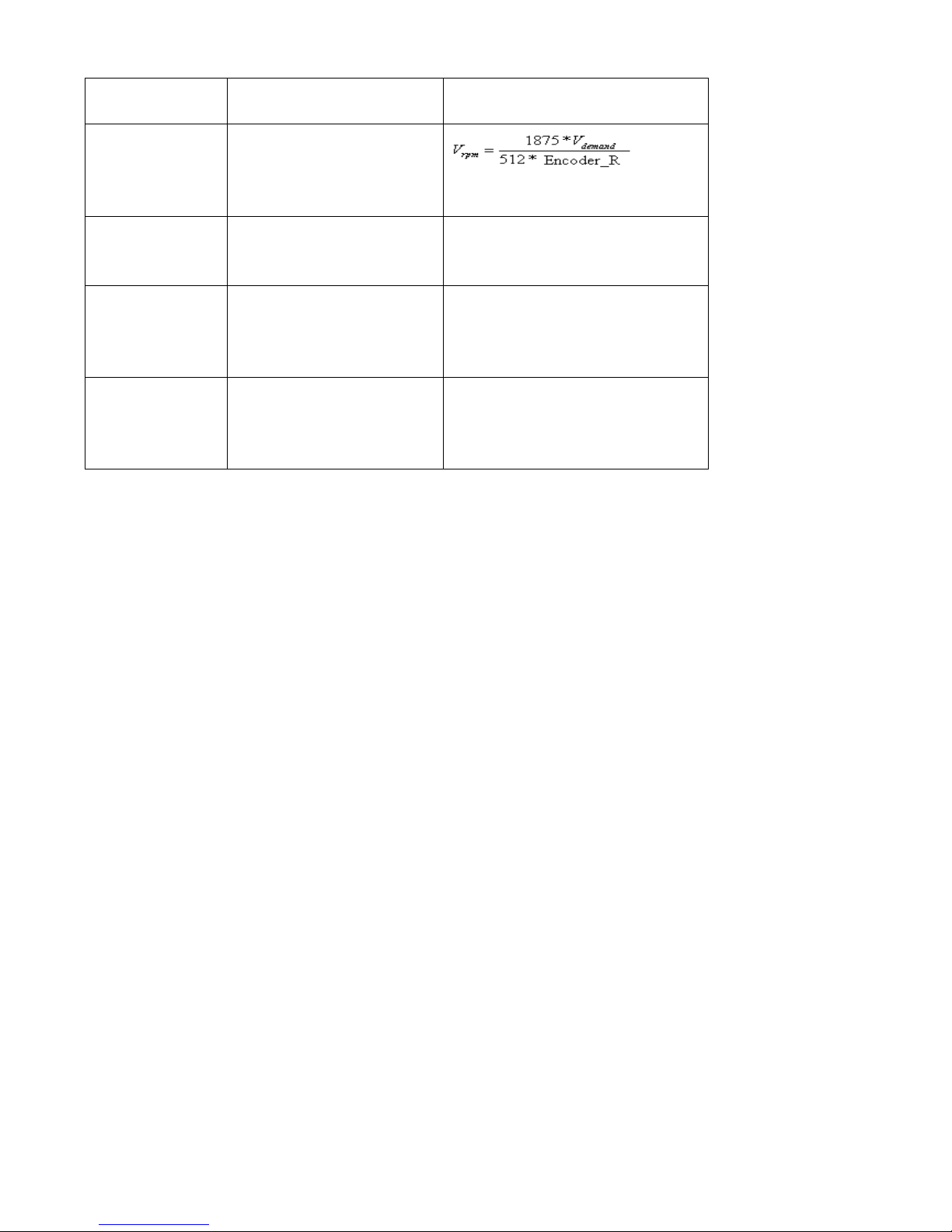
55
zone voltage that require
settings
Step 2
Calculate
demand
V
according
to the required speed
rpm
V
Step 3
Calculate
Factor
according
to
filter
U
and
demand
V
Step 5
Calculate
log_Ana Dead
according to the required
dead zone voltage
8191/10 log_ /
dead
v Ana Dead U
Step 5
Calculate
log_Ana Offset
according to the required
offset voltage
8191/10 log_ /
shift
v Ana Offset U
7.2.5 Examples of Analog – Speed Mode
In the analog – speed mode, follow the steps below to set a driver:
Step 1: Confirm whether it is necessary to enable the driver through external digital input ports. To enable the
driver through external digital input ports, see Table 6-12 in Example 6-3 for settings. If the driver does not
require enabling through external digital input ports, you can disable the enabling function of external digital
input ports by referring to Table 6-13 of Example 6-3, and enable the auto power-on function of the driver by
setting its internal parameters.
Step 2: Confirm whether limit switches are required. By default, the driver operates in the limit status after
being powered on. In this case, the numeric display has limit status display. If limit switches are unavailable,
please disable the function of limit switches by referring to Example 6-4.
Step 3: Confirm the mode switching positions and operation modes by referring to the settings in Example 6-5.
The factory default settings are as follows: When no signal is inputted to DIN3, the driver operates in the ―-4‖
mode (d3.16 = -4); when signal is inputted to DIN3, the driver operates in the ―-3‖ mode (d3.17 = -3). If the
driver is required to operate in the speed mode after being powered on, set d3.16 to -3 or 3.
Step 4: After configuring functions on digital input ports, select the analog – speed channel, and set
parameters such as analog – speed factors, dead zone, offset and filtering.
Step 5: Save parameters.
Example 7-3: Analog – speed mode (without setting the dead zone voltage
and offset voltage)
Requirement: DIN1 is used for enabling the driver, DIN2 is used for error resetting, and DIN3 controls the
operation modes of the driver (the mode is ―-3‖ when no signal is inputted, and is ―3‖ when signal is inputted).
Limit switches are unavailable. The voltage 10V corresponds to the rated rotation speed of 3000 rpm, and
-10V corresponds to the rated rotation speed of -3000 rpm. Select analog channel 1 (AIN1) to control the
speed.
filterdemand
UFactorV *
Page 56
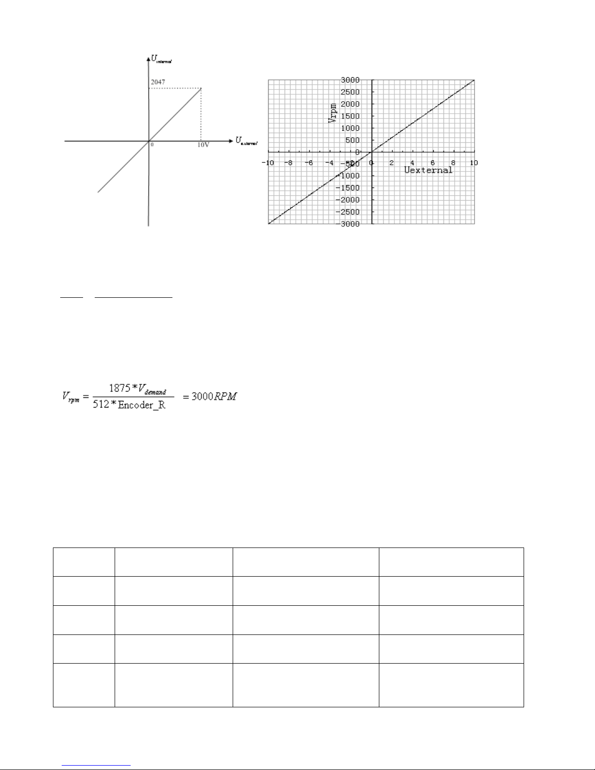
56
Fig. 7-7 Schematic diagram of Example 7-3
Calculate
filter
U
according to the offset voltage and dead zone voltage that require settings:
2047
10 10
filter
shift dead
U
v v U U
(In this example,
0
dead
U
, and
0
shift
U
)
Result:
filter
U
=2047
Calculate
demand
V
according to the required speed
rpm
V
:
(Encoder_R is 1000 inc/r)
Result:
8192000
demand
V
Calculate
Factor
according to
filter
U
and
demand
V
:
*
demand filter
V Factor U
Result:
4000Factor
Table 7-12 Parameter settings in Example 7-3
Numeric
Display
Variable Name
Meaning
Parameter Settings
d3.01
Din1_Function
Define the functions of digital
input port 1
000.1 (Driver enable)
d3.02
Din2_Function
Define the functions of digital
input port 2
000.2 (Error resetting)
d3.03
Din3_Function
Define the functions of digital
input port 3
000.4 (Control over operation
modes of drivers)
d3.05
Din5_Function
Define the functions of digital
input port 5
The default value 001.0
changes to 000.0 (position
positive limits are disabled)
Page 57
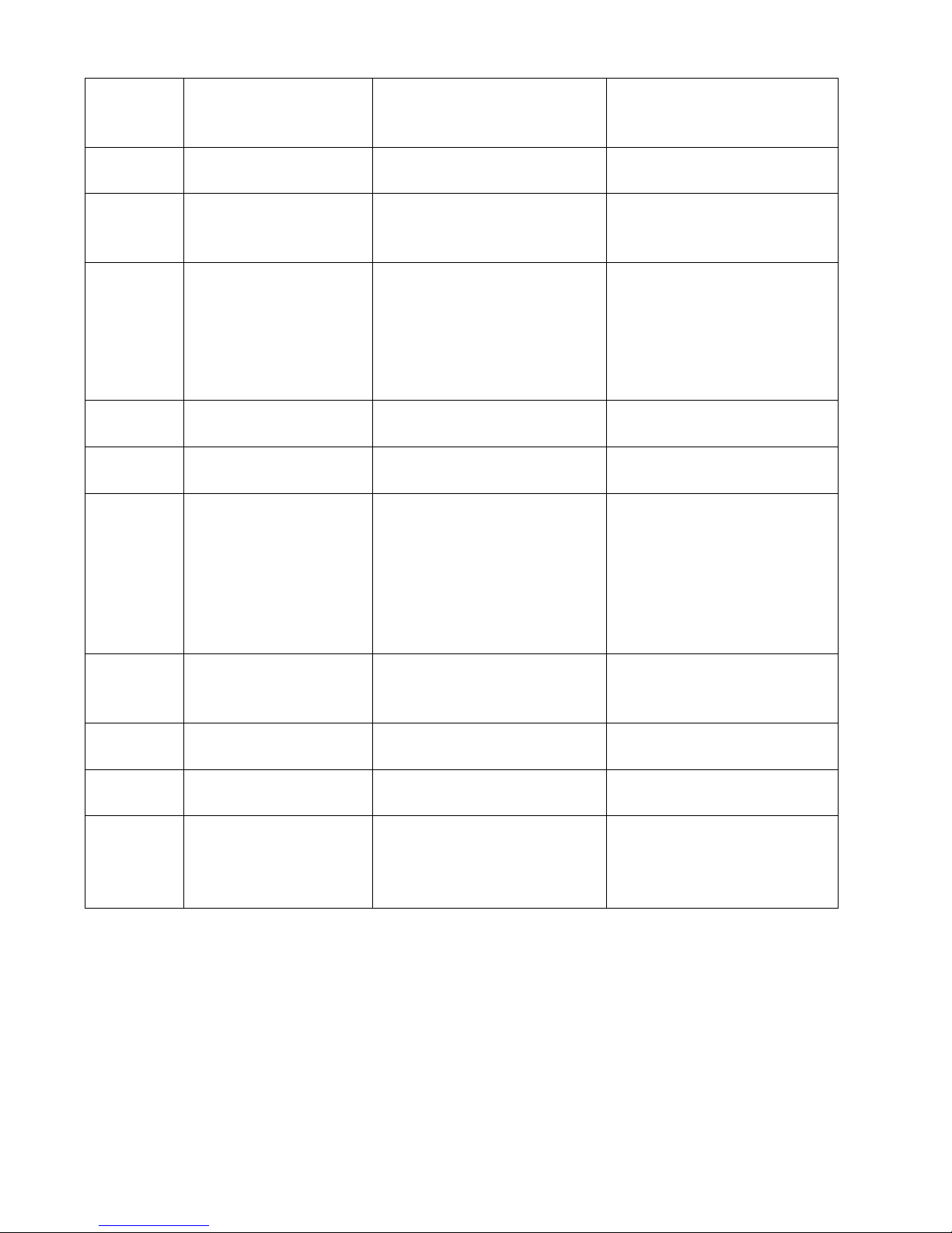
57
d3.06
Din6_Function
Define the functions of digital
input port 6
The default value 002.0
changes to 000.0 (position
negative limits are disabled)
d3.16
Din _Mode0
Select this operation mode
when input signals are invalid
Set to 0.003 (-3) mode
(instantaneous speed mode)
d3.17
Din _Mode1
Select this operation mode
when input signals are valid
Set to 0.003 (3) mode
(speed mode with
acceleration/deceleration)
d3.22
Analog1_Filter
Used to smooth the input
analog signals.
Filter frequency: f=4000/(2π*
Analog1_Filter)
Time Constant (T) =
Analog1_Filter/4000 (S)
d3.23
Analog1_Dead
Set dead zone data for external
analog signal 1
Set to 0
d3.24
Analog1_Offset
Set offset data for external
analog signal 1
Set to 0
d3.28
Analog_Speed_Con
Select analog-speed channels
0: Invalid analog channel
1: Valid analog channel 1
(AIN1)
2: Valid analog channel 2
(AIN2)
Valid mode -3 and mode 3
Set to 1
d3.29
Analog_Speed_Factor
Set the proportion between
analog signals and output
speed
Set to 4000
d2.10
Profile_Acce_16
Set the acceleration in
operation mode 3 and 1.(rps/s)
610 by defaut
d2.11
Profile_Dece_16
Set the deceleration in
operation mode 3 and 1.(rps/s)
610 by defaut
d3.00
Store_Loop_Data
1: Storing all configured
parameters for the control loop
10: Initializing all parameters for
the control loop
Set to 1
Example 7-4 Analog – speed mode (setting the dead zone voltage)
Requirement: The dead zone voltage ranges from - 0.5 V to 0.5 V, that is, the speed is 0 when the voltage
ranges from - 0.5 V to 0.5 V. The voltage 10 V corresponds to 3000 rpm, and -10 V corresponds to -3000 rpm.
Select analog channel 1 (AIN1) to control the speed.
Page 58
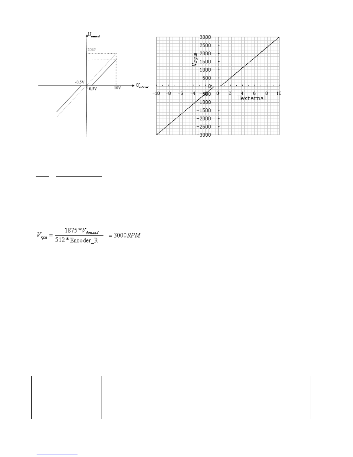
58
Fig. 7-8 Schematic diagram of Example 7-4
Calculate
filter
U
according to the offset voltage and dead zone voltage that require settings:
2047
10 10
filter
shift dead
U
v v U U
(In this example,
0
dead
U
.5, and
0
shift
U
)
Result:
filter
U
=1944
Calculate
demand
V
according to the required speed :
rpm
V
, (Encoder_R:10000 inc/r)
Result:
8192000
demand
V
Calculate
filter
U
according to
demand
V
and
Factor
:
*
demand filter
V Factor U
Result:
Factor
=4213
Calculate
log1_Ana Dead
according to the required dead zone voltage:
8191/10 log1_ /
dead
v Ana Dead U
Result:
log1_Ana Dead
=410
The following changes are required on the basis of Example 7-3.
Table 7-13 Parameter settings in Example 7-4
d3.23
Analog1_Dead
Sets dead zone data for
external analog signal 1
Set to 410
d3.29
Analog_Speed_Factor
Sets the proportion
between analog signals
and output speed
Set to 4213
Page 59
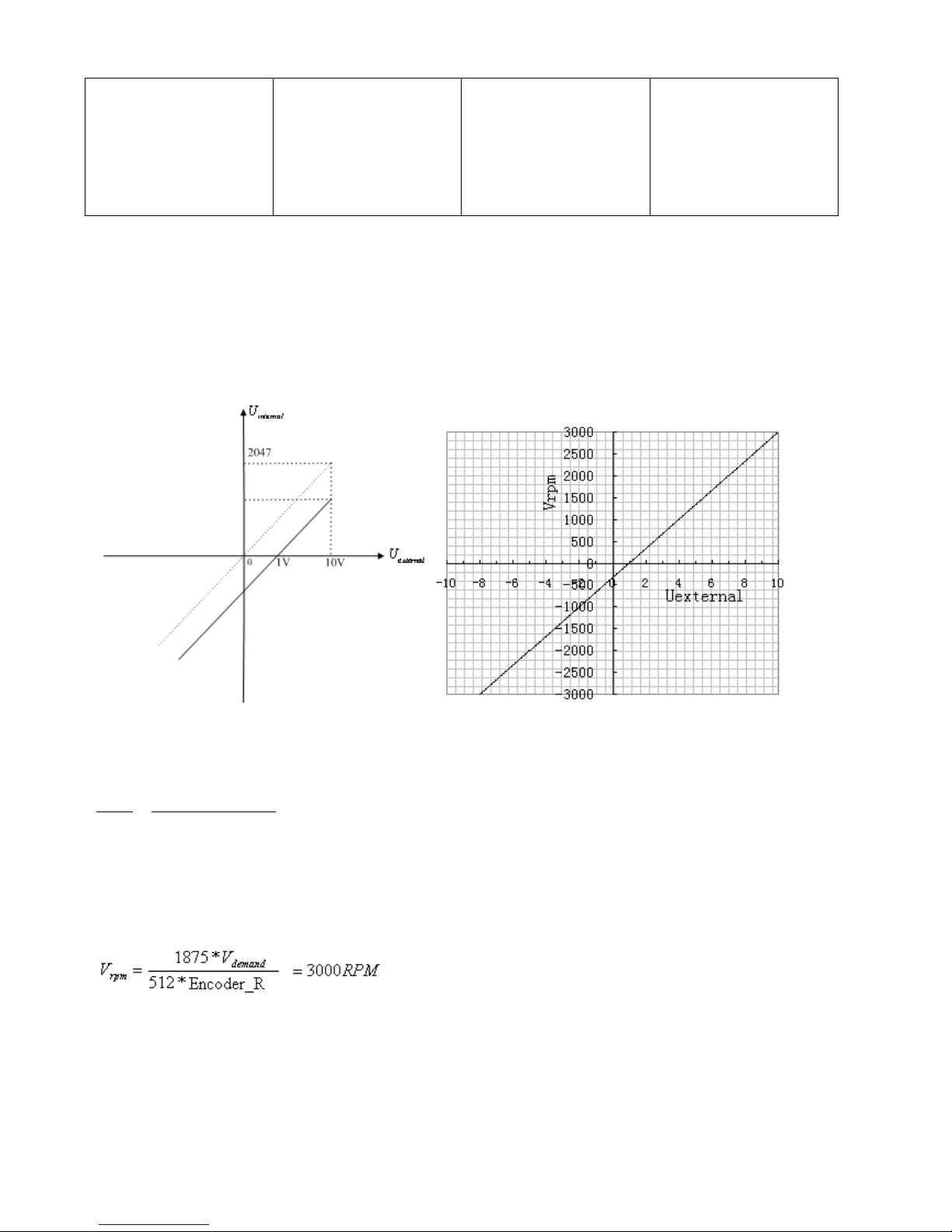
59
d3.00
Store_Loop_Data
1: Storing all configured
parameters for the
control loop
10: Initializing all
parameters for the
control loop
Set to 1
Example 7-5 Analog – speed mode (setting the offset voltage)
Requirement: The offset voltage is 1 V, that is, the speed is positive when the voltage is greater than 1 V, and
is negative when the voltage is less than 1 V. In this case, the voltage 10 V corresponds to 3000 rpm, and -9
V corresponds to -3000 rpm (in case of -10 V, the corresponding speed is less than -3000 rpm). Select analog
channel 1 (AIN1) to control the speed.
Fig. 7-9 Schematic diagram of Example 7-5
Calculate
filter
U
according to the offset voltage and dead zone voltage that require settings:
2047
10 10
filter
shift dead
U
v v U U
(In this example,
0
dead
U
, and
1
shift
U
)
Result:
Calculate
demand
V
according to the required speed :
rpm
V
, (Encoder_R:10000 inc/r)
Result:
8192000
demand
V
Calculate
filter
U
according to
demand
V
and
Factor
:
*
demand filter
V Factor U 1842
filter
U
Page 60
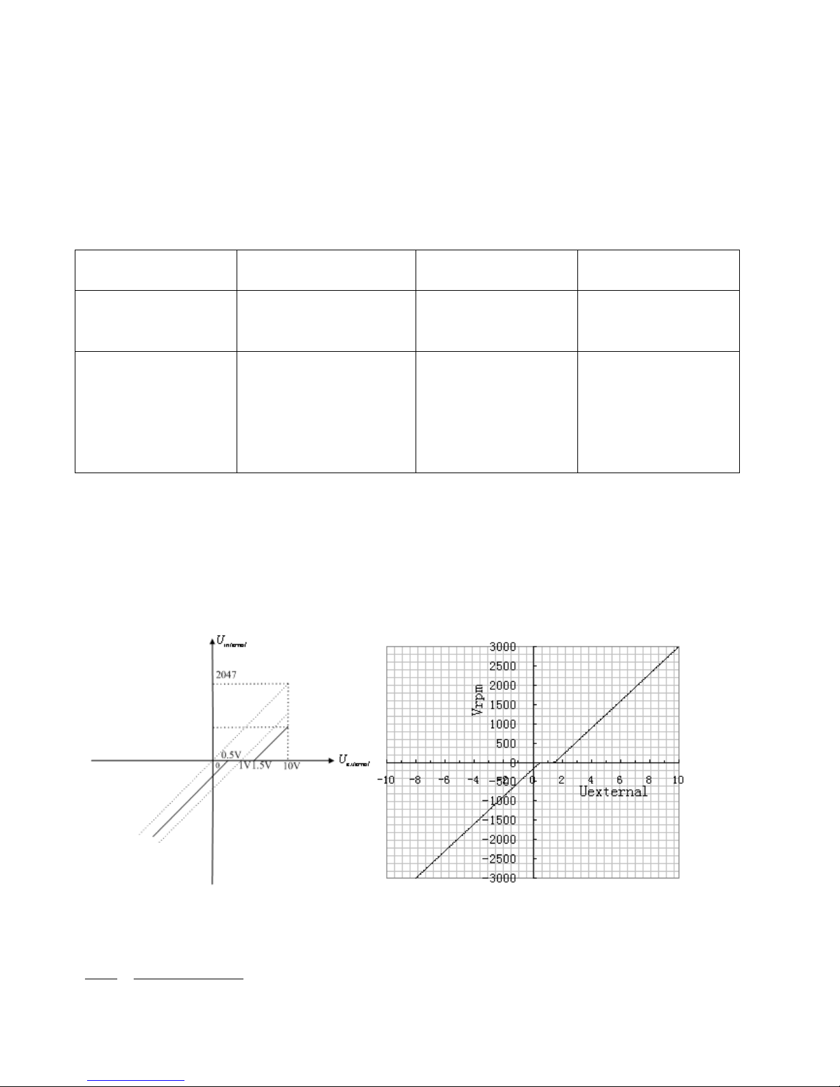
60
Result:
Factor
=4447
Calculate
log1_Ana Offset
according to the required offset voltage:
8191/10 log1_ /
shift
v Ana Offset U
Result:
log1_Ana Offset
=819
The following changes are required on the basis of Example 7-3.
Table 7-14 Parameter settings in Example 7-5
d3.24
Analog1_Offset
Sets offset data for
external analog signal 1
Set to 819
d3.29
Analog_Speed_Factor
Sets the proportion
between analog signals
and output speed
Set to 4447
d3.00
Store_Loop_Data
1: Storing all configured
parameters for the
control loop
10: Initializing all
parameters for the
control loop
Set to 1
Example 7-6: Analog – speed mode (setting the dead zone voltage and
offset voltage)
Requirement: Set the offset voltage to 1V, the dead zone voltage to 0.5V to 1.5V, and the max speed
corresponding to 10V to 3000 rpm. Select analog channel 1 (AIN1) to control the speed.
Fig. 7-10 Schematic diagram of Example 7-6
Calculate
filter
U
according to the offset voltage and dead zone voltage that require settings:
2047
10 10
filter
shift dead
U
v v U U
(In this example,
0
dead
U
.5, and
1
shift
U
)
Page 61
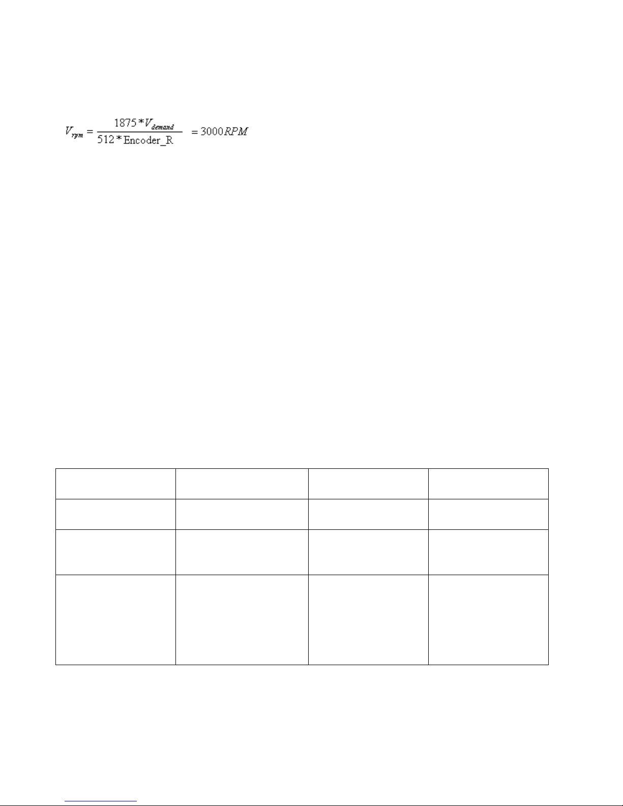
61
Result:
filter
U
=1740
Calculate
demand
V
according to the required speed :
rpm
V
, (Encoder_R:10000 inc/r)
Result:
8192000
demand
V
Calculate
Factor
according to
filter
U
and
demand
V
:
*
demand filter
V Factor U
Result:
Factor
=4708
Calculate
log1_Ana Dead
according to the required dead zone voltage:
8191/10 log1_ /
dead
v Ana Dead U
Result:
log1_Ana Dead
=409
Calculate
log1_Ana Offset
according to the required offset voltage:
8191/10 log1_ /
shift
v Ana Offset U
Result:
log1_Ana Offset
=819
The following changes are required on the basis of Example 7-3.
Table 7-15 Parameter settings in Example 7-6
d3.23
Analog1_Dead
Sets dead zone data for
external analog signal 1
Set to 409
d3.24
Analog1_Offset
Sets offset data for
external analog signal 1
Set to 819
d3.29
Analog_Speed_Factor
Sets the proportion
between analog signals
and output speed
Set to 4708
d3.00
Store_Loop_Data
1: Storing all configured
parameters for the
control loop
10: Initializing all
parameters for the
control loop
Set to 1
Page 62
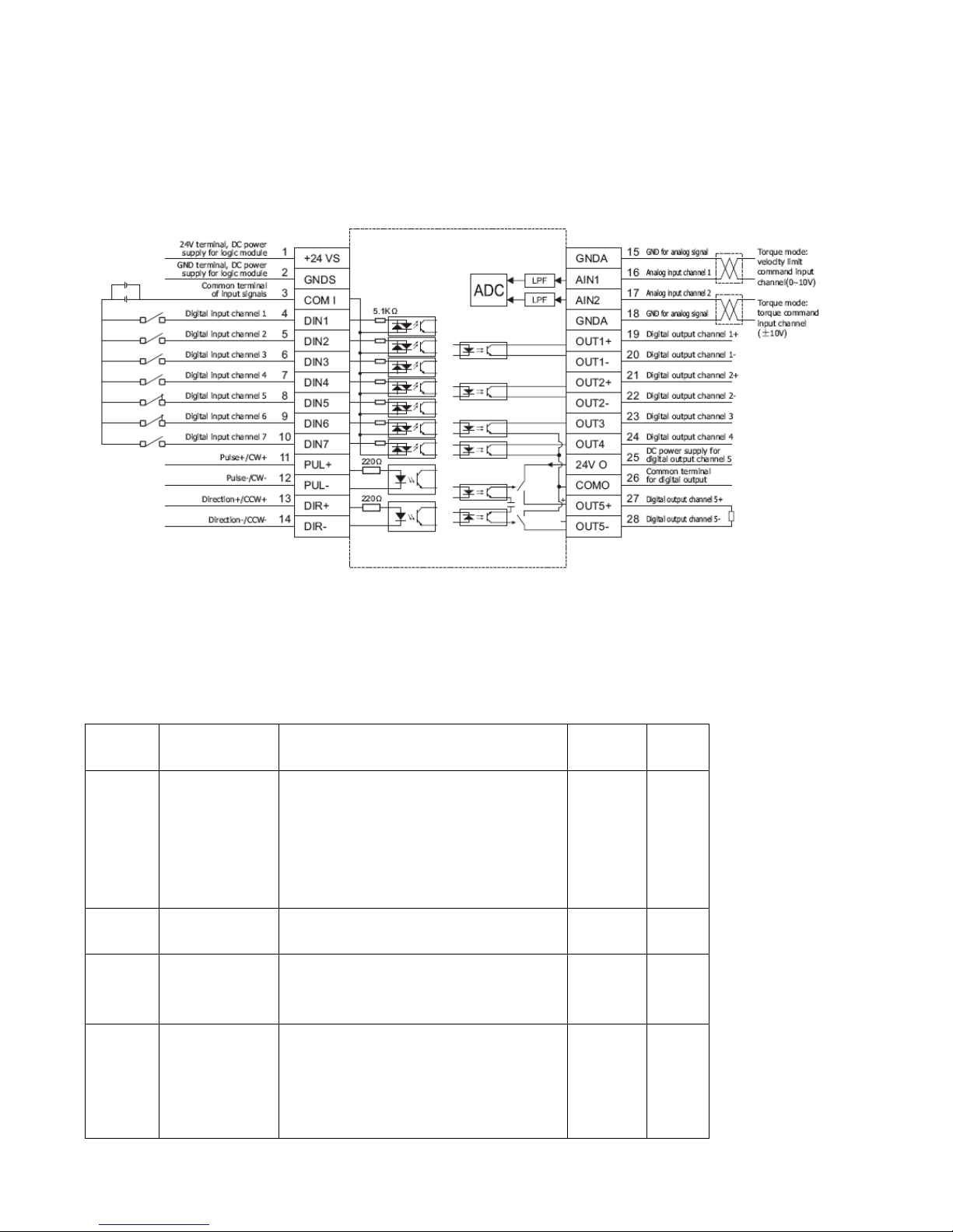
62
7.3 Torque Mode (“4” Mode)
7.3.1 Wiring in Analog – Torque Mode
Fig. 7-11 Interfaces in analog – torque mode
7.3.2 Parameters for Analog – Torque Mode
Table 7-16 Parameters for analog – torque mode
Numeric
Display
Variable Name
Meaning
Default
Value
Range
d3.22
Analog1_Filter
Used to smooth the input analog
signals.
Filter frequency: f=4000/(2π*
Analog1_Filter)
Time Constant: τ = Analog1_Filter/4000
(S)
5
1~127
d3.23
Analog1_Dead
Sets dead zone data for external analog
signal 1
0
0~819
2
d3.24
Analog1_Offse
t
Sets offset data for external analog
signal 1
0
-8192
~8192
d3.25
Analog2_Filter
Used to smooth the input analog
signals.
Filter frequency: f=4000/(2π*
Analog1_Filter)
Time Constant (T) =
5
1~127
Page 63
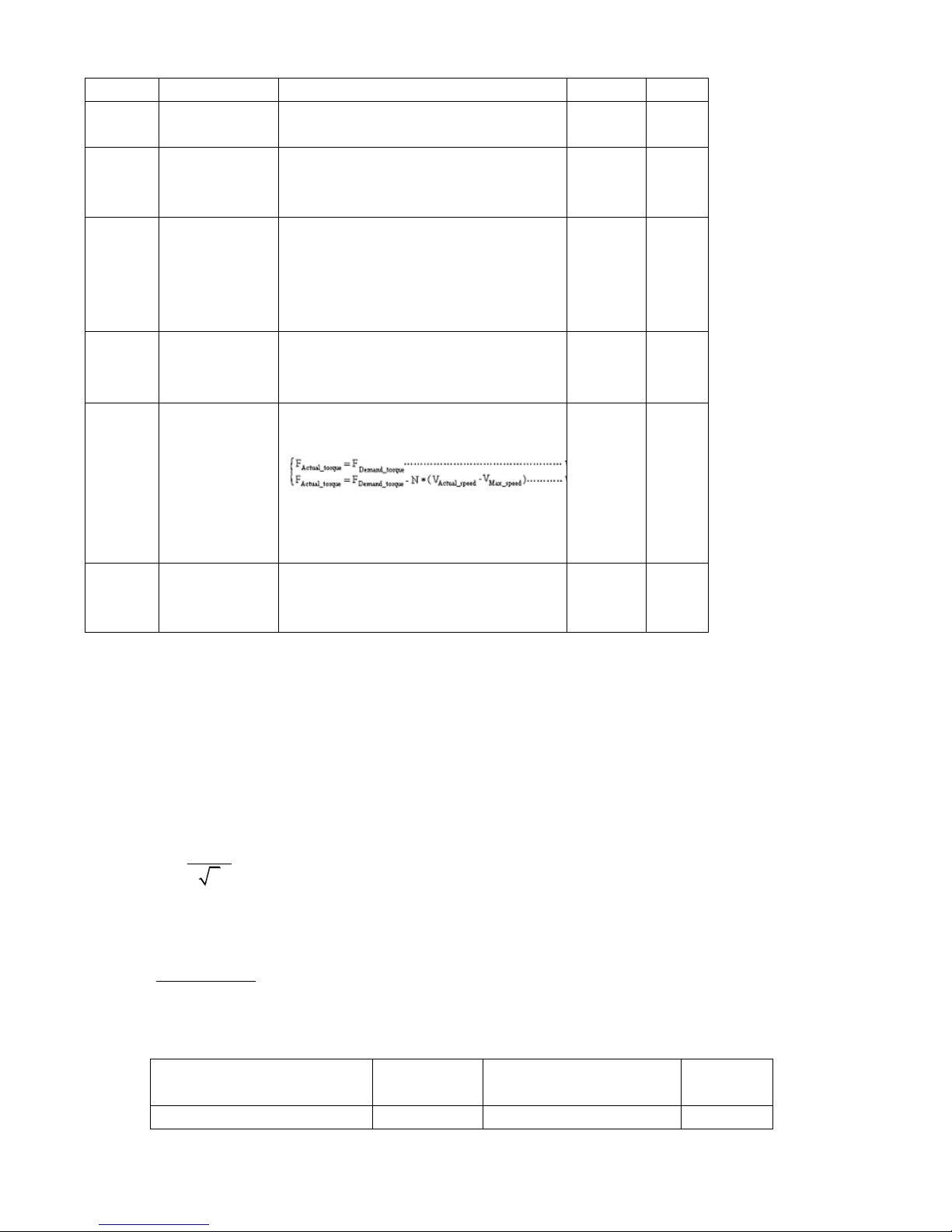
63
Analog2_Filter/4000 (S)
d3.26
Analog2_Dead
Sets dead zone data for external analog
signal 2
0
0~819
2
d3.27
Analog2_Offse
t
Sets offset data for external analog
signal 2
0
-8192
~8192
d3.30
Analog_Torqu
e_Con
Selects analog - torque channels
0: Invalid analog channel
1: Valid analog channel 1 (AIN1)
2: Valid analog channel 2 (AIN2)
Valid mode 4
0
N/A
d3.31
Analog_Torque
_Factor
Sets the proportion between analog
signals and output torque (current)
1000
N/A
d2.15
Speed_Limit_F
actor
The factor that limits the maximum
speed in the torque mode
V
max_speed
complies with d2.24
Max_Speed_RPM parameter settings.
10
0~100
0
d2.24
Max_Speed_R
PM
Limits the max rotation speed of the
motor
5000
0~600
0
7.3.3 Analog Signal Processing
In the analog – torque mode, external analog command signals are directly inputted to the current loops
in the driver, thus directly controlling target current through the internal current loop. Analog signal is
processed in the same way as that in the analog – speed mode.
In the analog – torque mode,
demand
I
is calculated according to the specified
demand
T
with the formula of
*
2
demand
demand t
I
TK
(
t
K
is a torque constant).
Factor
is calculated according to
demand
I
and
filter
U
with the formula of
*
*
2048*2048
filter
demand
Factor U
I Ipeak
(
Ipeak
indicates the peak current of a driver).
Table 7-17
t
K
and
Ipeak
parameters
Motor Model
t
K
(Nm/A)
Driver Model
Ipeak
(A)
SMH60S-0020-30AXK-3LKX
0.48
CD420-0020-0016-AA-000
15
Page 64
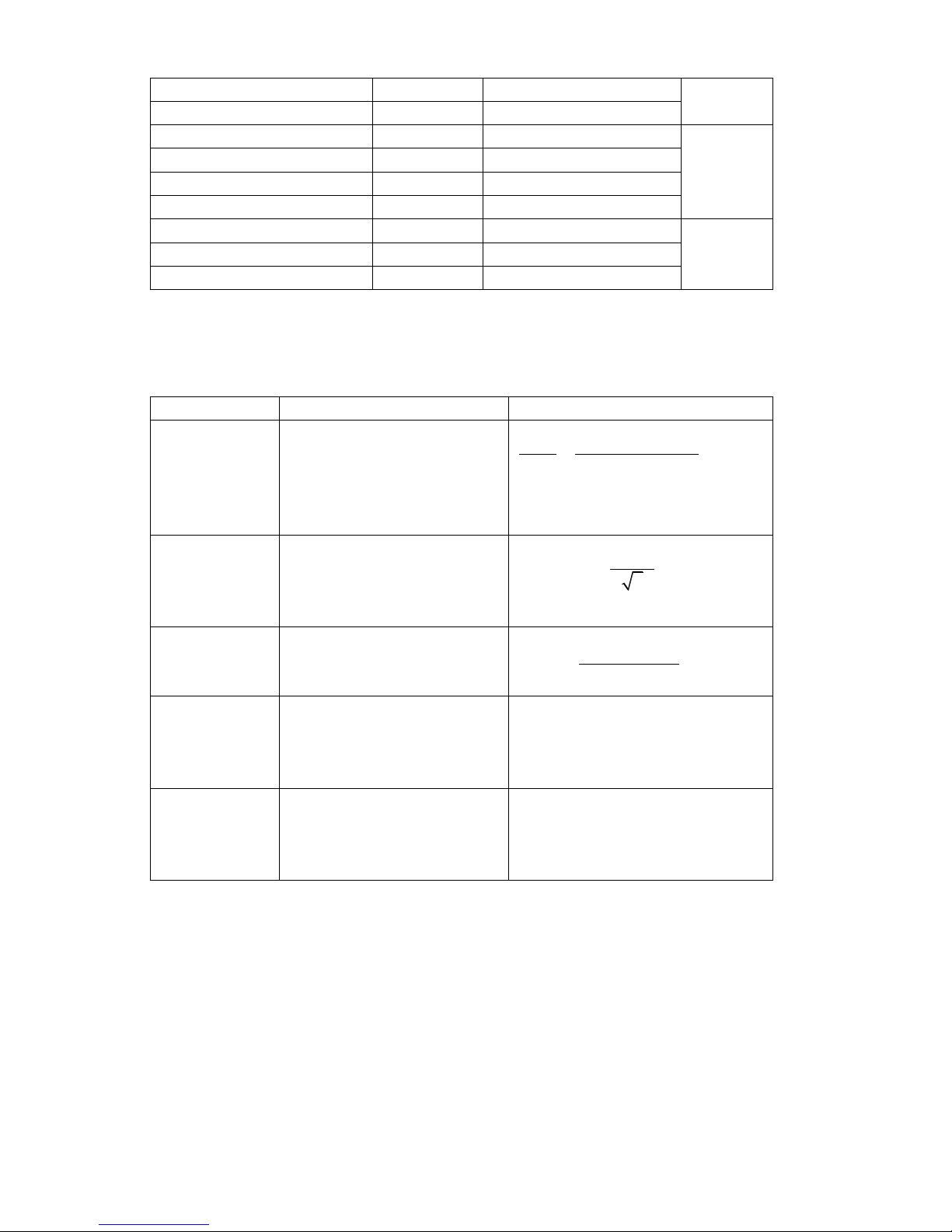
64
SMH60S-0040-30AXK-3LKX
0.48
CD420-0040-0031-AA-000
SMH80S-0075-30AXK-3LKX
0.662
CD420-0075-0039-AA-000
SMH80S-0100-30AXK-3LKX
0.562
CD430-0100-0063-AA-000
27.5
SMH110D-0105-20AXK-4LKX
0.992
CD430-0105-0054-AA-000
SMH110D-0125-30AXK-4LKX
0.744
CD430-0125-0065-AA-000
SMH110D-0126-20AXK-4LKX
1.058
CD430-0126-0062-AA-000
SMH110D-0126-30AXK-4HKX
1.058
CD620-0126-0043-AA-000
25
SMH110D-0157-30AXK-4HKX
0.992
CD620-0157-0054-AA-000
SMH110D-0188-30AXK-4HKX
1.058
CD620-0188-0062-AA-000
7.3.4 Calculation Procedure for Analog – Torque Mode
Table 7-17 Calculation procedure for analog – torque mode
Procedure
Method
Formula
Step 1
Calculate
filter
U
according to
the offset voltage and dead
zone voltage that require
settings
2047
10 10
filter
shift dead
U
v v U U
Step 2
Calculate
demand
I
according to
the required torque
demand
T
*
2
demand
demand t
I
TK
Step 3
Calculate
Factor
according to
filter
U
and
demand
I
*
*
2048*2048
filter
demand
Factor U
I Ipeak
Step 4
Calculate
log_Ana Dead
according to the required dead
zone voltage
8191/10 log_ /
dead
v Ana Dead U
Step 5
Calculate
log_Ana Offset
according to the required offset
voltage
8191/10 log_ /
shift
v Ana Offset U
7.3.5 Examples of Analog – Torque Mode
In the analog – torque mode, follow the steps below to configure a driver:
Step 1: Confirm whether it is necessary to enable the driver through external digital input ports. To enable the
driver through external digital input ports, see Table 6-12 in Example 6-3 for settings. If the driver does not
require enabling through external digital input ports, you can disable the enabling function of external digital
input ports by referring to Table 6-13 of Example 7-3, and enable the auto power-on function of the driver by
setting its internal parameters.
Step 3: Confirm mode switching positions and operation modes by referring to the settings in Example 6-5.
Page 65
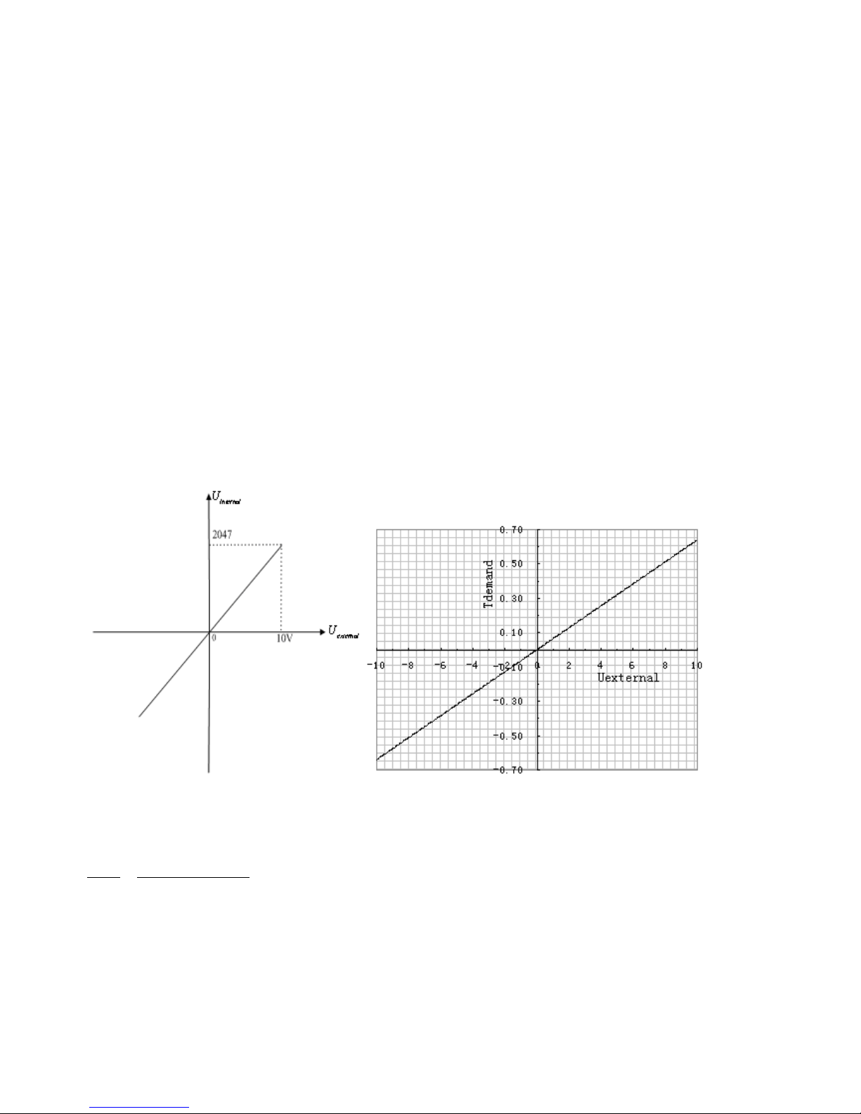
65
The factory default settings for the driver are as follows: When no signal is inputted to DIN3, the driver
operates in the ―-4‖ mode (d3.16 = -4); when signal is inputted to DIN3, the driver operates in the ―-3‖ mode
(d3.17 = -3). If the driver is required to operate in the torque mode (―4‖ mode), please set d3.16 or d3.17 to 4.
In case d3.16 = 4, if DIN3 has no input signals when the driver is powered on, the driver operates in the ―4‖
mode. In case d3.17 = 4, if DIN3 has input signals, the driver operates in the ―4‖ mode.
Step 3: After configuring functions on digital input ports, select the analog – torque channel, and set
parameters such as analog – torque factors, dead zone, offset, filtering, speed limit factors, and max speed
limits.
Step 4: Save parameters.
Example 7-7: Analog – torque mode (without setting the dead zone voltage
and offset voltage)
Requirement: DIN1 is used for enabling the driver, DIN2 is used for error resetting, and DIN3 controls the
operation modes of the driver (the mode is ―4‖ when no signal is inputted, and is ―3‖ when signal is inputted).
The motor Kt is 0.48 Nm/A, and the peak current of drivers is 15 A. The analog input voltage -10 V
corresponds to -0.64 Nm, and 10 V corresponds to 0.64 Nm. Select analog channel 2 (AIN1) to control the
torque.
Fig. 7-12 Schematic diagram of Example 7-7
Calculate
filter
U
according to the offset voltage and dead zone voltage that require settings:
2047
10 10
filter
shift dead
U
v v U U
(In this example,
0
dead
U
, and
0
shift
U
)
Result:
filter
U
=2047
Calculate
demand
I
according to the required torque
demand
T
:
Page 66
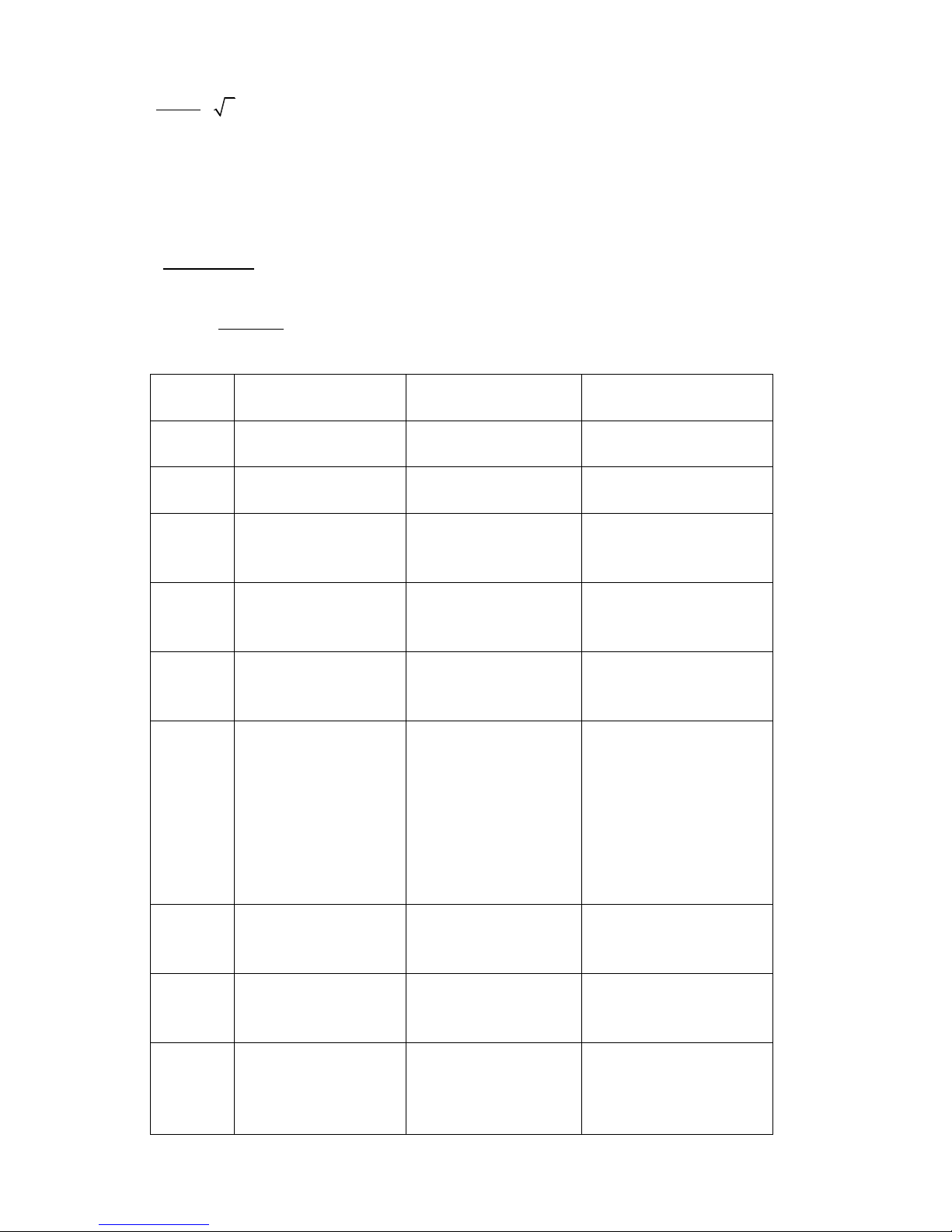
66
*2
demand
demand
t
T
I
K
Result:
demand
I
=1.89
Calculate
Factor
according to
filter
U
and
demand
I
:
*2048*4096
*
demand
filter
I
Factor
U Ipeak
Result:
1.89
*2048*4096 515
2047*15
Factor
Table 7-18 Parameter settings in Example 7-7
Numeric
Display
Variable Name
Meaning
Parameter Settings
d3.01
Din1_Function
Defines the functions of
digital input port 1
000.1 (Driver enable)
d3.02
Din2_Function
Defines the functions of
digital input port 2
000.2 (Error resetting)
d3.03
Din3_Function
Defines the functions of
digital input port 3
000.4 (Control over
operation modes of
drivers)
d3.16
Din _Mode0
Select this operation
mode when input
signals are invalid
Set to 0004 (4) mode
(torque mode)
d3.17
Din _Mode 1
Select this operation
mode when input
signals are valid
Set to 0.003 (3) mode
(speed mode with
acceleration/deceleration)
d3.25
Analog2_Filter
Used to smooth the
input analog signals.
Filter frequency:
f=4000/(2π*
Analog1_Filter)
Time Constant: T =
Analog2_Filter/4000
(S)
d3.26
Analog2_Dead
Sets dead zone data
for external analog
signal 2
Set to 0
d3.27
Analog2_Offset
Sets offset data for
external analog signal
2
Set to 0
d3.31
Analog_Torque_Factor
Sets the proportion
between analog signals
and output torque
(current)
Set to 515
Page 67
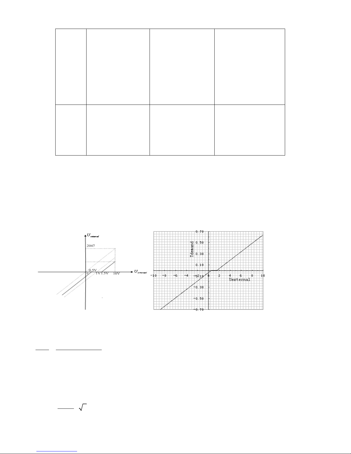
67
d3.30
Analog_Torque_Con
Selects analog - torque
channels
0: Invalid analog
channel
1: Valid analog channel
1 (AIN1)
2: Valid analog channel
2 (AIN2)
Valid mode 4
Set to 2
d3.00
Store_Loop_Data
1: Storing all
configured parameters
for the control loop
10: Initializing all
parameters for the
control loop
Set to 1
Example 7-8: Analog – torque mode (setting the dead zone voltage and
offset voltage)
Requirement: The offset voltage is 1V, and the dead zone voltage is 0.5V. The motor Kt is 0.48 Nm/A, and the
peak current of the driver is 15A. The analog input voltage 10V corresponds to 0.64Nm. Select analog
channel 2 (AIN2) to control the torque.
Fig. 7-13 Schematic diagram of Example 7-8
Calculate
filter
U
according to the offset voltage and dead zone voltage that require settings:
2047
10 10
filter
shift dead
U
v v U U
(In this example,
0
dead
U
.5, and
1
shift
U
)
Result:
filter
U
=1740
Calculate
demand
I
according to the required torque
demand
T
:
*2
demand
demand
t
T
I
K
Page 68

68
Result:
demand
I
= 1.89
Calculate
Factor
according to
filter
U
and
demand
I
:
*2048*4096
*
demand
filter
I
Factor
U Ipeak
Result:
1.89
*2048*4096 606
1740*15
Factor
Calculate
log2_Ana Dead
according to the required dead zone voltage:
8191
2_ *
10
dead
Analog Dead U
v
Result:
log2_Ana Dead
= 410
Calculate
log2_Ana Offset
according to the required offset voltage:
8191
2_ *
10
shift
Analog Offset U
v
Result:
log2_Ana Offset
=819
The following changes are required on the basis of Example 7-7.
Table 7-19 Parameter settings in Example 7-8
d3.26
Analog2_Dead
Sets dead zone data for
external analog signal 2
Set to 410
d3.27
Analog2_Offset
Sets offset data for
external analog signal 2
Set to 819
d3.31
Analog_Torque_Factor
Sets the proportion
between analog signals
and output torque
(current)
Set to 2362
d3.00
Store_Loop_Data
1: Storing all configured
parameters for the
control loop
10: Initializing all
parameters for the
control loop
Set to 1
7.4 Internal Multi-position Control Modes (“1” Mode)
In Internal multi-position control mode, we can activate internal set target position though an external signal to
control motors. The activation has two preconditions:
1, multi-position control mode can only be activated in Mode 1, it can’t be activated in other modes.
2, At least one of the external input signal is defined as ―Internal position control 0‖, ―Internal position control 1
― or ―Internal position control 2 ―, which means at least one address of digital tubes-d3.01 ~ d3.07 is set to
Page 69
69
―040.0‖’, ―080.0‖ or ―800.2.
―Internal position control 0‖ , ―Internal position control 1‖ and ―Internal position control 2 ―, these three
signals will be combined into binary codes used to select a target position between ―Position 0~7‖.
Table 7-20 Internal Multi-position Control Mode Parameter Table
Note: In this control mode, ―position section X‖ can be positive or negative, it can be flexibly set; while the
corresponding speed must be positive. Other parameters such as acceleration, deceleration, etc, can use the
default value; also can be changed through digital tube.
Example7-9: Internal multi-position control mode
A motor needs to go four position sections. In position section 0, it should reach the 5000 pulse location at the
speed of 100RPM.In position section 1, it should reach the 15000 pulse location at the speed of 150RPM.In
position section 2, it should reach the 28500 pulse location at the speed of 175RPM.In position section 3, it
should reach the -105000 pulse location at the speed of 200RPM. In position section 4, it should reach the
-20680 pulse location at the speed of 300RPM. In position section 5, it should reach the -30550 pulse location
at the speed of 325RPM. In position section 6, it should reach the 850 pulse location at the speed of 275RPM.
In position section 7, it should reach the 15000 pulse location at the speed of 460RPM.
Table 7-21 Internal Multi-position Control Mode Demand
DIN1
The driver is enabled, the motor shaft is locked
Internal
position
control
0
Internal
position
control
1
Internal
position
control
2
Corresponding
position
Position section
numberic display
Corresponding
speed
Speed
section
numberic
display
0 0 0
Din_Pos0
d3.40select position
section sequence
number
d3.41select position
section high bit
d3.42select position
section low bit
Din_Speed0_RPM
d3.18
0 0 1
Din_Pos1
Din_Speed1_RPM
d3.19
0 1 0
Din_Pos2
Din_Speed2_RPM
d3.20
0 1 1
Din_Pos3
Din_Speed3_RPM
d3.21
1 0 0
Din_Pos4
Din_Speed4_RPM
d3.44
1 0 1
Din_Pos5
Din_Speed5_RPM
d3.45
1 1 0
Din_Pos6
Din_Speed6_RPM
d3.46
1 1 1
Din_Pos7
Din_Speed7_RPM
d3.47
Page 70
70
DIN3
Driver working mode(invalid 1,valid-3)
DIN4
Internal position 0
DIN5
Internal position 1
DIN6
Internal position 2
DIN6:DIN5:DIN4=0:0:0
Select position and speed in section 0
DIN6:DIN5:DIN4=0:0:1
Select position and speed in section 1
DIN6:DIN5:DIN4=0:1:0
Select position and speed in section 2
DIN6:DIN5:DIN4=0:1:1
Select position and speed in section 3
DIN6:DIN5:DIN4=1:0:0
Select position and speed in section 4
DIN6:DIN5:DIN4=1:0:1
Select position and speed in section 5
DIN6:DIN5:DIN4=1:1:0
Select position and speed in section 6
DIN6:DIN5:DIN4=1:1:1
Select position and speed in section 7
DIN6
Activate command(execute the selected
position section)
1. Define the meanings of the input points:
Table 7-22 Internal Multi-position Control Mode Configuration
Numberic
display
Variable name
Configuration way
d3.01
Din1_Function
000.1(Driver enabled)
d3.03
Din3_Function
000.4(Set driver mode)
d3.04
Din4_Function
040.0(Internal position control 0)
d3.05
Din5_Function
080.0(Internal position control 1)
d3.06
Din6_Function
800.2 (Internal position control 2)
d3.07
Din7_Function
400.0(Activate command)
d3.16
Din_mode 0
Set 0001(1)Mode
Internal multi-position control mode
d3.17
Din_mode 1
Set 0.004 (-4) Mode
Pulse-control mode
d3.00
Storage parameters
1(Storage configuration parameters)
2. Set position and speed:
Table 7-23 Internal Multi-position and Speed Configuration
Numberic
display
Variable Name
Parameters Settings
d3.43
Relative / Absolute position selection
Set to 2F(absolute location)
d3.40
Set the position section number to 0
Set to 0(select position section
0)
d3.41
Set the high bit of position section
(N*10000)
Set to 0
d3.42
Set the low bit of position section
Set to 5000(set the position of
section 0 t0 5000)
Page 71
71
d3.18
Set the speed of section 0
Set to 100( set the speed of
section 0 to 100)
d3.40
Set the position section number to 1
Set to 1(select position section
1)
d3.41
Set the high bit of position section
(N*10000)
Set to 1
d3.42
Set the low bit of position section
Set to 15000(set the position of
section 1 t0 15000))
d3.19
Set the speed of position section 1
Set to 150( set the speed of
section 1 to 150)
d3.40
Set the position section number to2
Set to 2(select position section
2)
d3.41
Set the high bit of position section
(N*10000)
Set to 2
d3.42
Set the low bit of position section
Set to 28500(set the position of
section 2 t0 28500)
d3.20
Set the speed of position section 1
Set to 175( set the speed of
section 2 to 175)
d3.40
Set the position section number to 3
Set to 3(select position section
3)
d3.41
Set the high bit of position section
(N*10000)
Set to 3
d3.42
Set the low bit of position section
Set to 10500(set the position of
section 3 t0 10500)
d3.20
Set the speed of position section 3
Set to 200( set the speed of
section 3 to 200)
d2.10
Acceleration
Default 610 rps/s
d2.11
Deceleration
Default 610 rps/s
d3.00
Storage parameter
1 ( storage configuration
parameters)
Set all these parameters, then:
1. Enable the driver, which means to make the digital input DIN1 high-level.
2. Select the position section, which means to change the electrical level of DIN4 and DIN5.
3. Activate instructions and execute the program, which means to make the digital input DIN6 high-level.
Notice:
In multi-position control mode, select location method by setting the different value of the digital tube d3.43.If
you choose absolute positioning mode, set it to ―F‖; if the instructions require immediate updating, set it
to ―2F‖; if you choose relative positioning method, set it to ―4F‖or ‖84F‖.To change these parameters
successfully, you have to save the value of d3.00,and then restart.
7.5 Internal Multi-speed Control Modes (“-3” or “3” Mode)
In this control mode, external input signals are used to activate the internally configured target speed to
control the motor. There are two prerequisites for activation:
1. Multi-speed control is available in the ―-3‖ or ―3‖ mode, and is unavailable in other modes.
Page 72
72
2. Set d3.28 to 0. In this case, the analog – speed channel is invalid.
3. At least one external input signal DinX_Function defines Bit8 or Bit9.
For example, define Din2_Function corresponding to Din2 as 010.0, and Din3_Function corresponding
to Din3 as 020.0. In this way, the combination of the two above signals is used to choose any one of
Din_Speed0_RPM, Din_Speed1_RPM, Din_Speed2_RPM or Din_Speed3_RPM as the target speed.
Table 7-24 Parameters for internal multi-speed control modes
Internal Speed
Control 0
(Din_Sys.Bit8)
Internal Speed
Control 1
(Din_Sys.Bit9)
Meaning
Numeric
Display
Valid Object
(numeric display
operation)
0 0 Multi-speed
control: 0 [rpm]
d3.18
Din_Speed0_RPM
1 0 Multi-speed control
1 [rpm]
d3.19
Din_Speed1_RPM
0 1 Multi-speed control
2 [rpm]
d3.20
Din_Speed2_RPM
1 1 Multi-speed control
3 [rpm]
d3.21
Din_Speed3_RPM
Note: If you need to set the target speed precisely, it is required to set Din_Speed0, Din_Speed1,
Din_Speed2 and Din_Speed3 with a host computer. The four data units are internal units and are suitable for
users who are familiar with drivers. Din_SpeedX_RPM indicates the data after converting Din_SpeedX into
the unit of rpm to facilitate users. Conversion involves both the reading and writing processes, and does not
require calculation by users.
Example 7-10: Internal multi-speed control
Requirement: You need to define the digital input ports DIN6 and DIN7 as internal speed control, DIN1
as driver enabling and DIN2 as operation mode control of the driver (the mode is ―3‖ when the driver is valid,
and is ―-3‖ when the driver is invalid). For detailed requirements, see Table 7-25. For the setting method, see
Table 7-26.
Table 7-25 Requirements on internal multi-speed control
DIN6:DIN7=0:0
To execute the multi-step 1 speed (100 rpm)
DIN6:DIN7=1:0
To execute the multi-step 2 speed (200 rpm)
DIN6:DIN7=0:1
To execute the multi-step 3 speed (300 rpm)
DIN6:DIN7=1:1
To execute the multi-step 3 speed (400 rpm)
DIN1
To enable the driver, and lock the motor shaft
DIN2
To control operation modes of the driver (the mode is ―3‖
when the driver is valid, and is ―-3‖ when the driver is
invalid)
Table 7-26 Setting methods for internal multi-speed control
Numeric Display
Variable Name
Setting Method
d3.01
Din1_Function
Set to 000.1
(Driver enable)
d3.02
Din2_Function
Set to 000.4
(control over operation modes of drivers)
d3.06
Din6_Function
Set to 010.0
Page 73
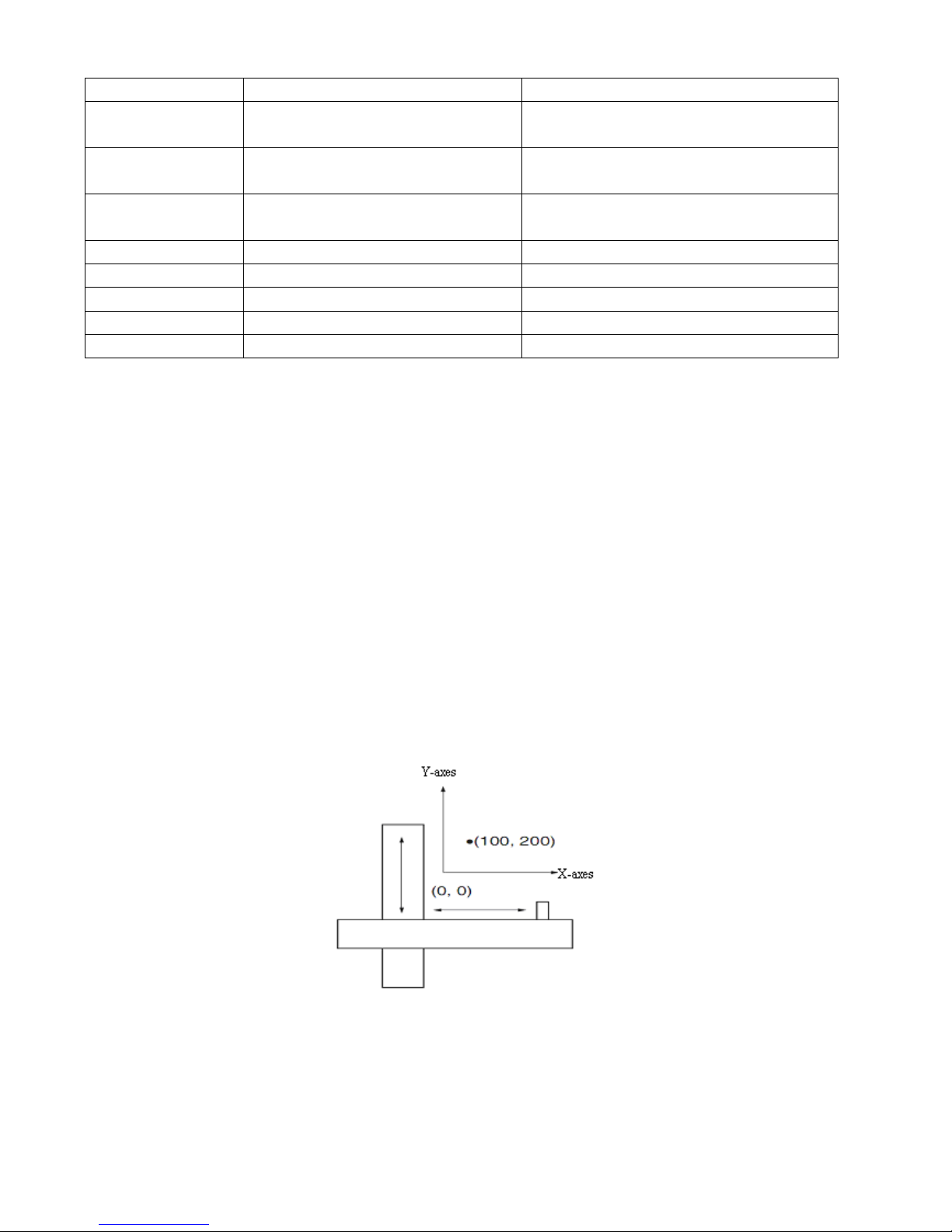
73
(internal speed control 0)
d3.07
Din7_Function
Set to 020.0
(internal speed control 1)
d3.16
Din_Mode0
Set to 0.003 (3) mode
(speed mode with acceleration/deceleration)
d3.17
Din_Mode1
Set to 0.003 (-3) mode
(instantaneous speed mode)
d3.18
Din_Speed0_RPM
Set to 100 [rpm]
d3.19
Din_Speed1_RPM
Set to 200 [rpm]
d3.20
Din_Speed2_RPM
Set to 300 [rpm]
d3.21
Din_Speed3_RPM
Set to 400 [rpm]
d3.00
Store_Loop_Data
Set to 1
7.6 Internal Torque Control Mode (“4” Mode)
In the internal torque mode, only the current loop of the driver operates. Set d0.03 (CMD_q target current)
parameter directly to obtain the desired target torque. The prerequisite is that d3.30 must be set to 0. In this
case, the analog–torque channel is invalid.
7.7 Homing Mode (“6” Mode)
1, Summary
To make a system execute positioning in accordance with its absolute positioning, the first step is to define
the origin. For instance, as shown in the following XY plane, to navigate to (X, Y) = (100mm, 200mm), you
must define the origin of the machine firstly. It’s necessary to define the origin.
2, Procedure of homing
Use the following steps to homing:
1. Set the external I / O parameters, and then save.
2. Set the data for homing, and then save.
3. Execute homing.
Page 74
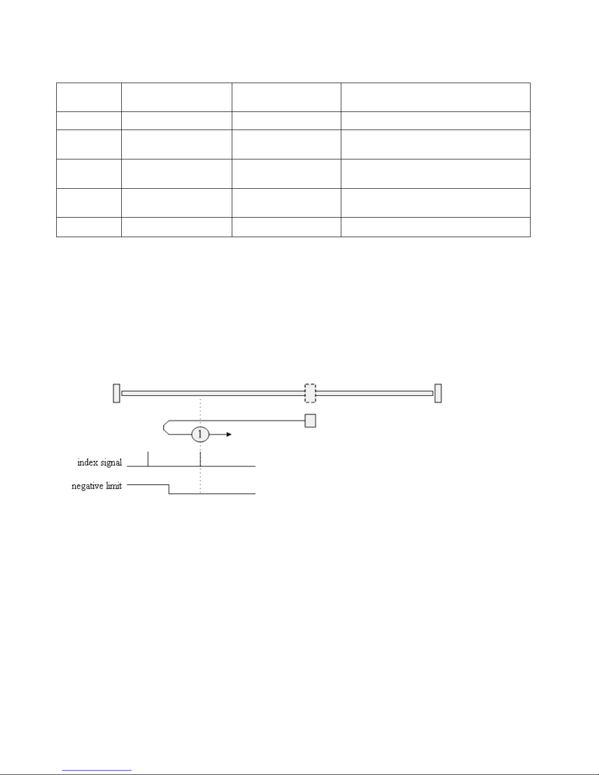
74
3, Configuration of the data for homing
Here are simple descriptions of the data for executing homing.
CD has 27 methods for homing, referring the CANopen’s definition of DSP402.
1st-14th methods use Z signal as homing signal.
17th-30th methods use external signal as homing signal.
Method 1: Homing on the negative limit switch and index pulse
Using this method, the initial direction of movement is leftward if the negative limit
switch is inactive (here shown as low). The home position is at the first index pulse to the
right of the position where the negative limit switch becomes inactive.
Method 2: Homing on the positive limit switch and index pulse
Using this method, the initial direction of movement is rightward if the positive limit
switch is inactive (here shown as low). The position of home is at the first index pulse to
the left of the position where the positive limit switch becomes inactive.
0x607C0020
Home_Offset
Home offset
In Homing mode, set the offset relative to
the zero point.
0x60980008
Homing_Method
Homing method
Select the homing method
0x60990120
Homing_Speed_Switch
Speed for searching
the limit switch
Set the speed for searching the limit
switch which defined as homing signal.
0x60990220
Homing_Speed_Zero
Speed for searching
the Zero point.
Only valid when find Index signal.
0x60990308
Homing_Power_On
Homing when power
on
Every time after power on,it will start
homing once.
0x609A0020
Homing_Accelaration
Homing acceleration
Control the acceleration of homing
Page 75
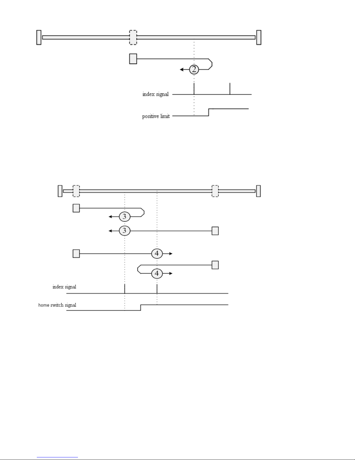
75
Methods 3 and 4: Homing on the positive home switch and index pulse
Using methods 3 or 4, the initial direction of movement is dependent on the state of the
home switch. The home position is at the index pulse to either the left or right of the pint
where the home switch changes state. If the initial position is sited so that the direction of
movement must reverse during homing, the point at which the reversal takes place is
anywhere after a change of state of the home switch.
Methods 5 and 6: Homing on the negative home switch and index pulse
Using methods 5 or 6, the initial direction of movement is dependent on the state of the
home switch. The home position is at the index pulse to either the left or the right of the
point where the home switch changes state. If the initial position is sited so that the
direction of movement must reverse during homing, the point at which the reversal takes
place is anywhere after a change of state of the home switch.
Page 76
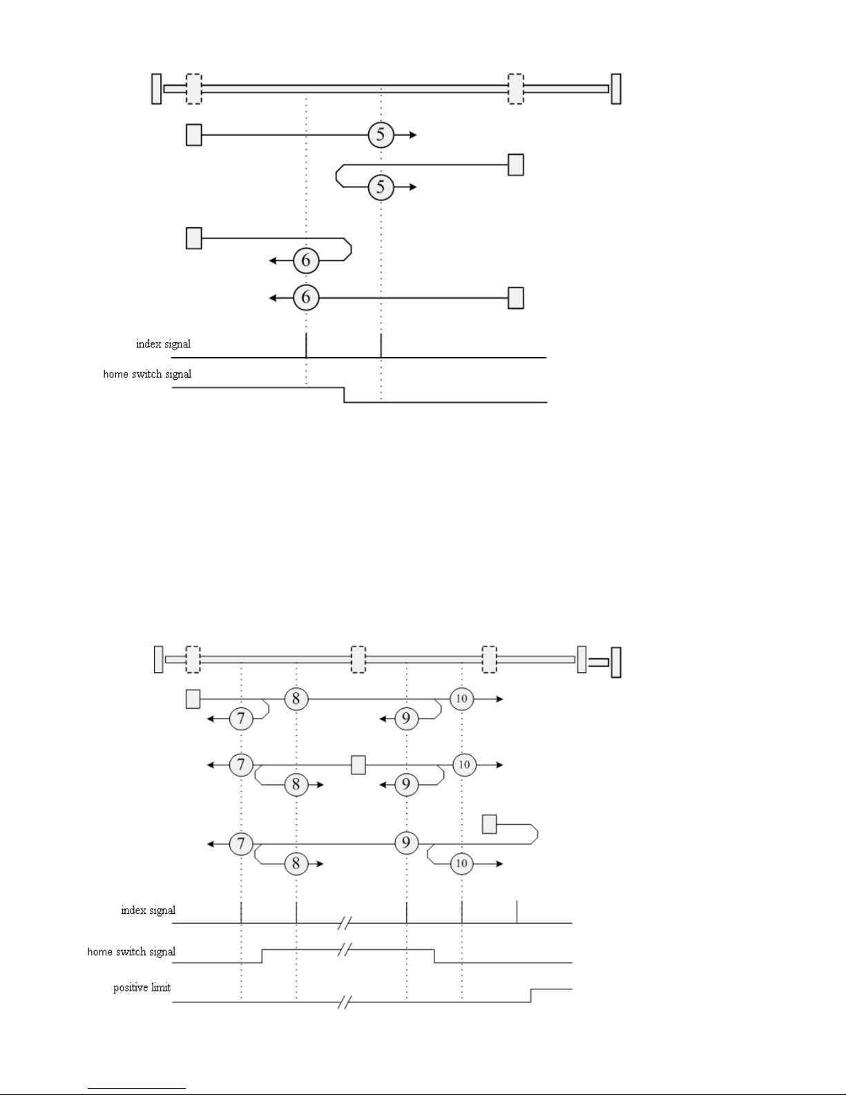
76
Methods 7 to 14: Homing on the home switch and index pulse
These methods use a home switch that is active over only a portion of the travel; in effect
the switch has a ―momentary‖ action as the axle position sweeps past the switch.
Using methods 7 to 10, the initial direction of movement is to the right, and using
methods 11 to 14, the initial direction of movement is to the left, except if the home
switch is active at the start of motion. In this case, the initial direction of motion is
dependent on the edge being sought. The home position is at the index pulse on either
side of the rising or falling edges of the home switch, as shown in the following two
diagrams. If the initial direction of movement leads away from the home switch, the
drive must reverse on encountering the relevant limit switch.
Page 77
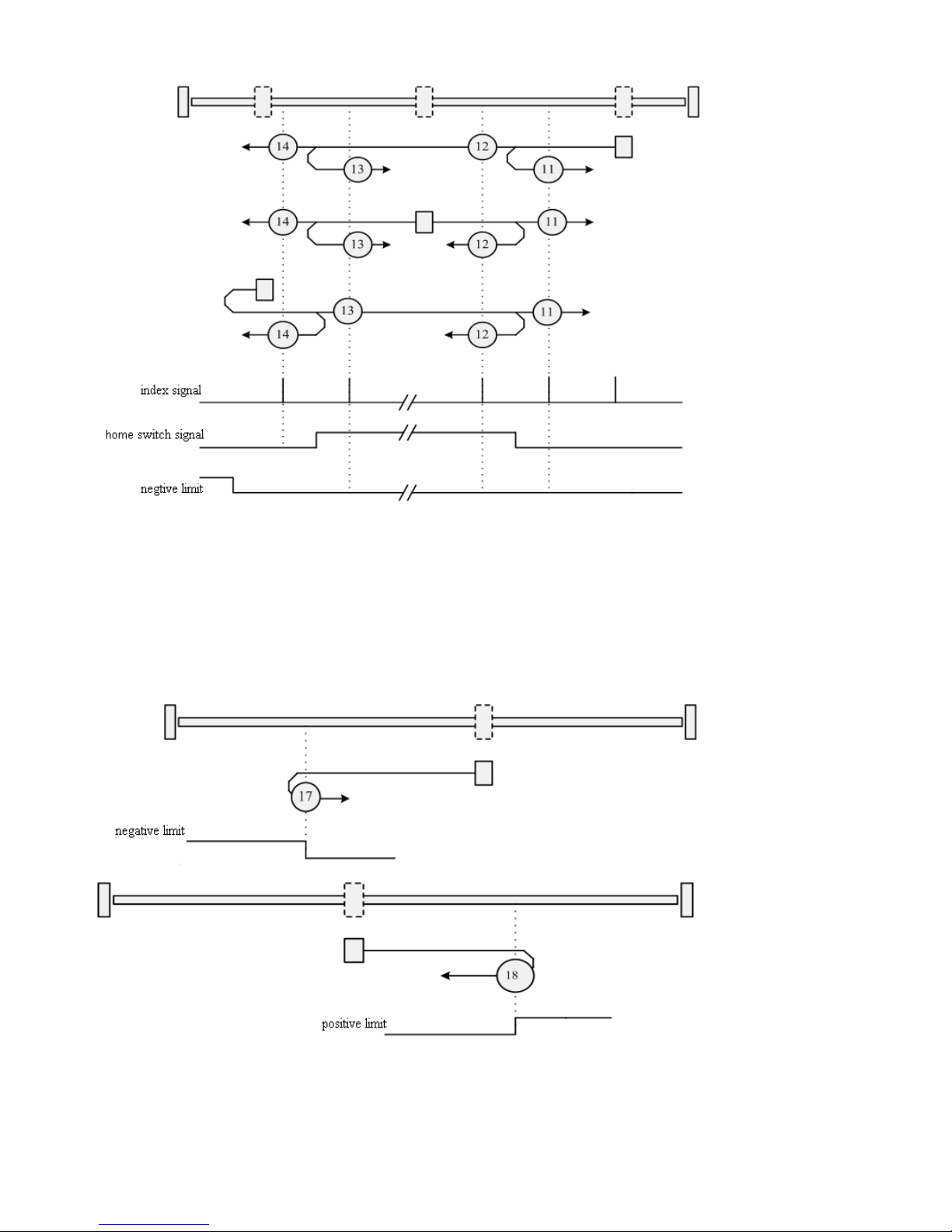
77
Methods 15 and 16: Reserved
These methods are reserved for future expansion of the homing mode.
Methods 17 to 30: Homing without an index pulse
These methods are similar to methods 1 to 14, except that the home position is not
dependent on the index pulse; it is dependent only on the relevant home or limit switch
transitions. For example, methods 19 and 20 are similar to methods 3 and 4, as shown in
the following diagram:
Page 78
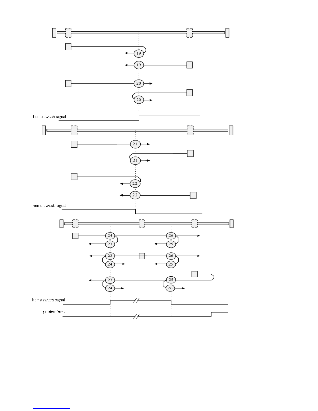
78
Page 79
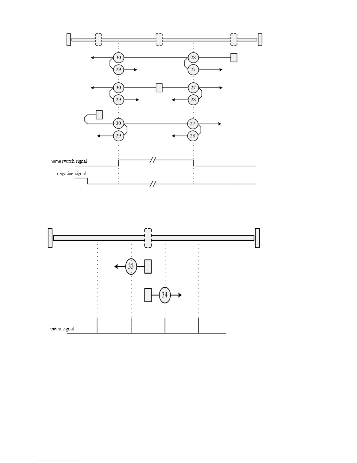
79
Methods 31 and 32: Reserved
These methods are reserved for future expansion of the homing mode.
Methods 33 and 34: Homing on the index
Method 35: Homing on the current position
In this method, the current position is taken to be the home position.
Methods -17 and -18: Use the mechanical terminal as reference point
Page 80
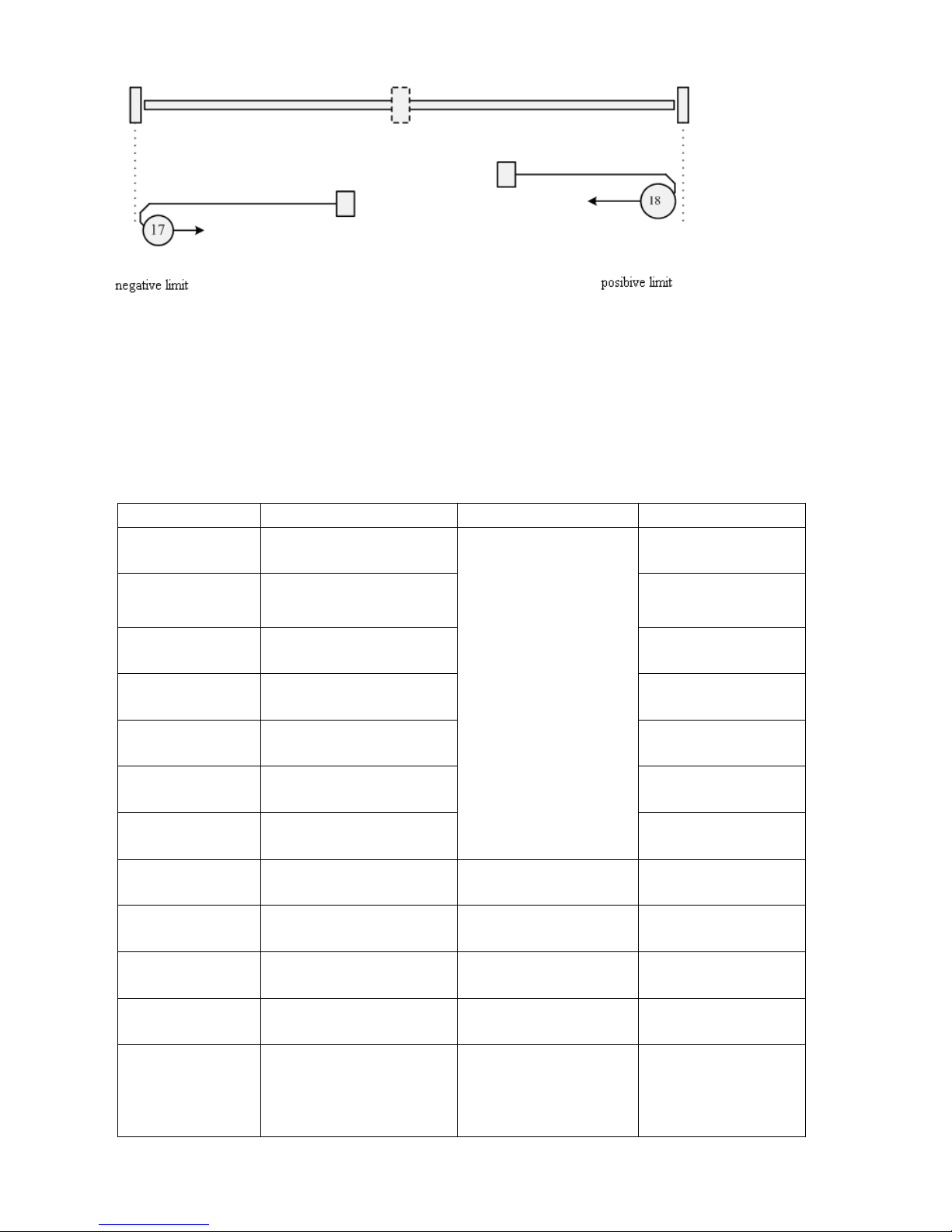
80
Example 7-11:Using method 7 for homing.
1. Set parameters.
Numberic display
Parameter Name
meaning
Setting Value
d3.01
Din1_Function
000.1: Driver enabled
000.2: Driver error reset
000.4: Operation mode
001.0:Positive limit
002.0:Negative limit
004.0:Origin signal
200.0:Start homing
000.1
(Driver enabled)
d3.02
Din2_Function
000.2
(Driver error reset)
d3.03
Din3_Function
000.4
(Driver model control)
d3.04
Din4_Function
200.0
(Start homing)
d3.05
Din5_Function
001.0
(Positive limit)
d3.06
Din6_Function
002.0
(Negative limit)
d3.07
Din7_Function
004.0
(Home signal)
d3.14
Dout4_Function
004.0:Index signal appears
004.0
(Index signal appears)
d3.15
Dout4_Function
040.0:Origin found
040.4
(origin found)
d3.16
Din_Mode0
Select this mode when the
input signal is invalid
0.004 (-4)
d3.17
Din_Mode1
Select this mode when the
input signal is valid
0.003 (-3)
d3.00
Store_Loop_Data
1:Storage all the setting
parameters except those of
motor
10:Initialize all the setting
0001 (1)
Page 81
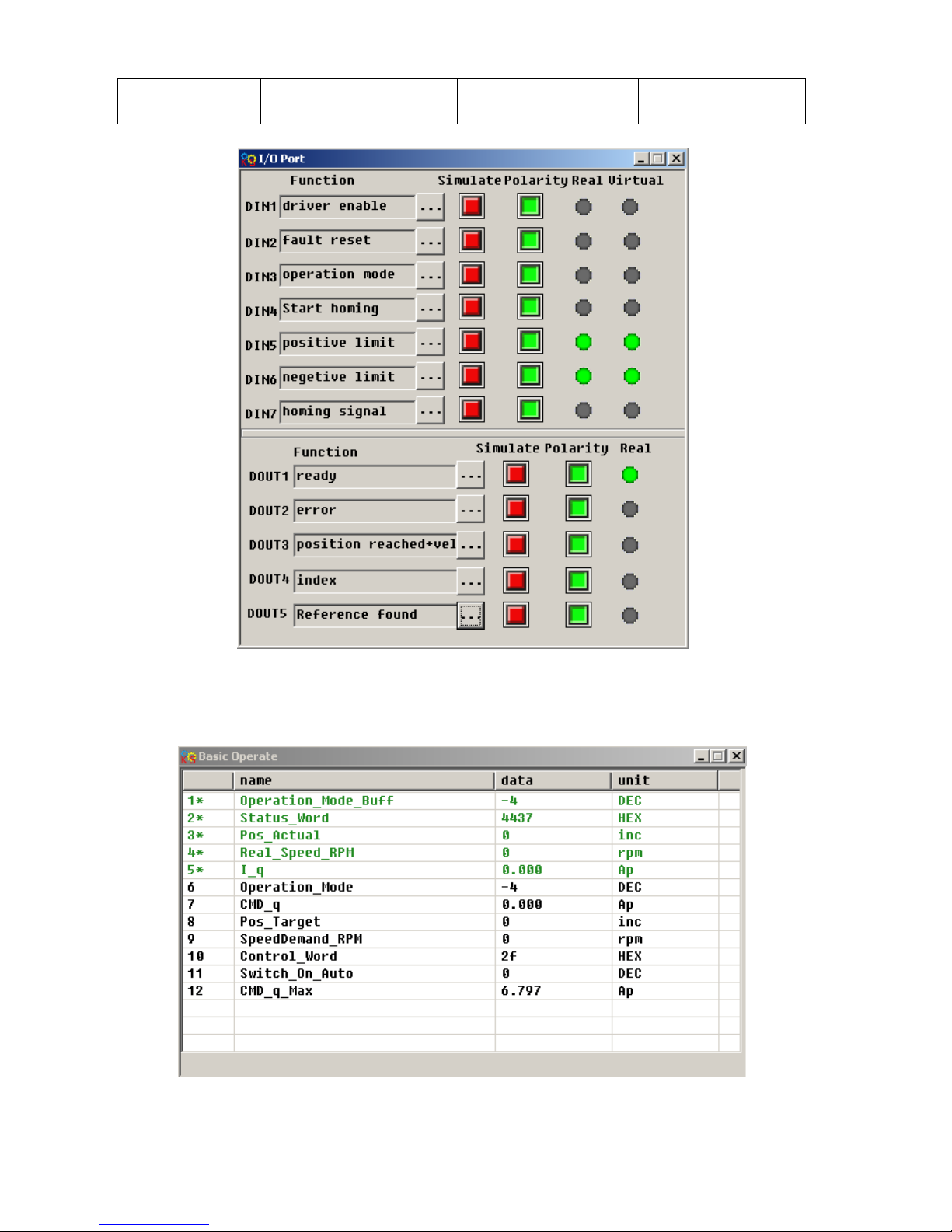
81
parameters except those of
motor
At this time, computer software shows:
Notice: The positive and negative limits are default to normally closed point. Otherwise, the Panel will alarm
and display P.L (positive limit) and N.L (No limit). Only when the alarm is eliminated, the origin control mode
can be normally used.
Computer monitoring status is:
2. Set parameters for homing.
Page 82
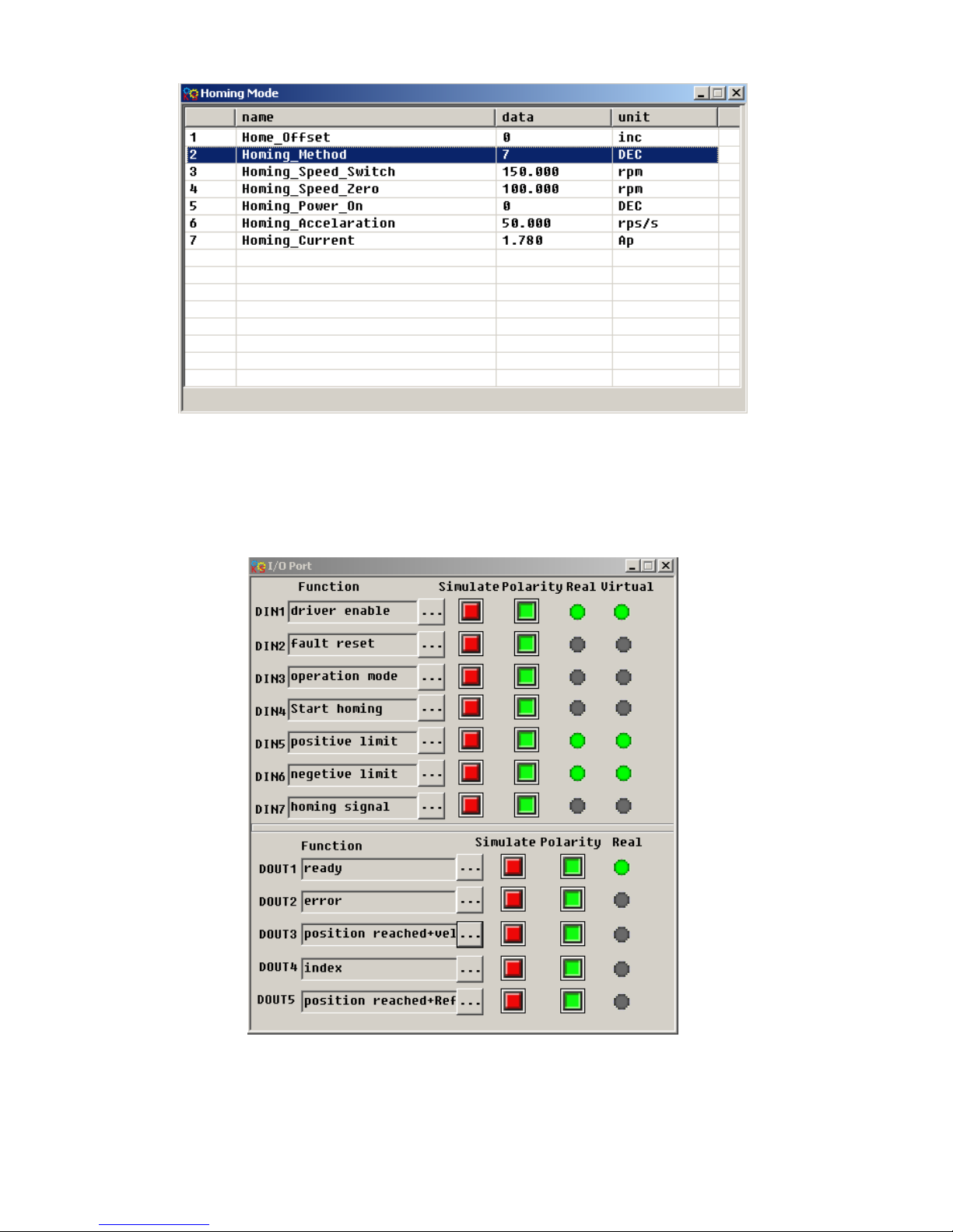
82
In common circumstance, only need to set up the model of origin and the rest of the parameters are default.
In some case, ―Electrify and then find the origin‖ is set to 1, at the same time the definition-- ―Start finding the
origin‖ is eliminated.
3. Start homing.
(1). Enable motor, which means the digital input point 1 is set to high-level. The computer motoring picture is
shown below:
(2). Send ―Start finding the origin‖ signal to motor, which means the digital input point 4 is set to high-level.
The computer motoring picture is shown below:
Page 83
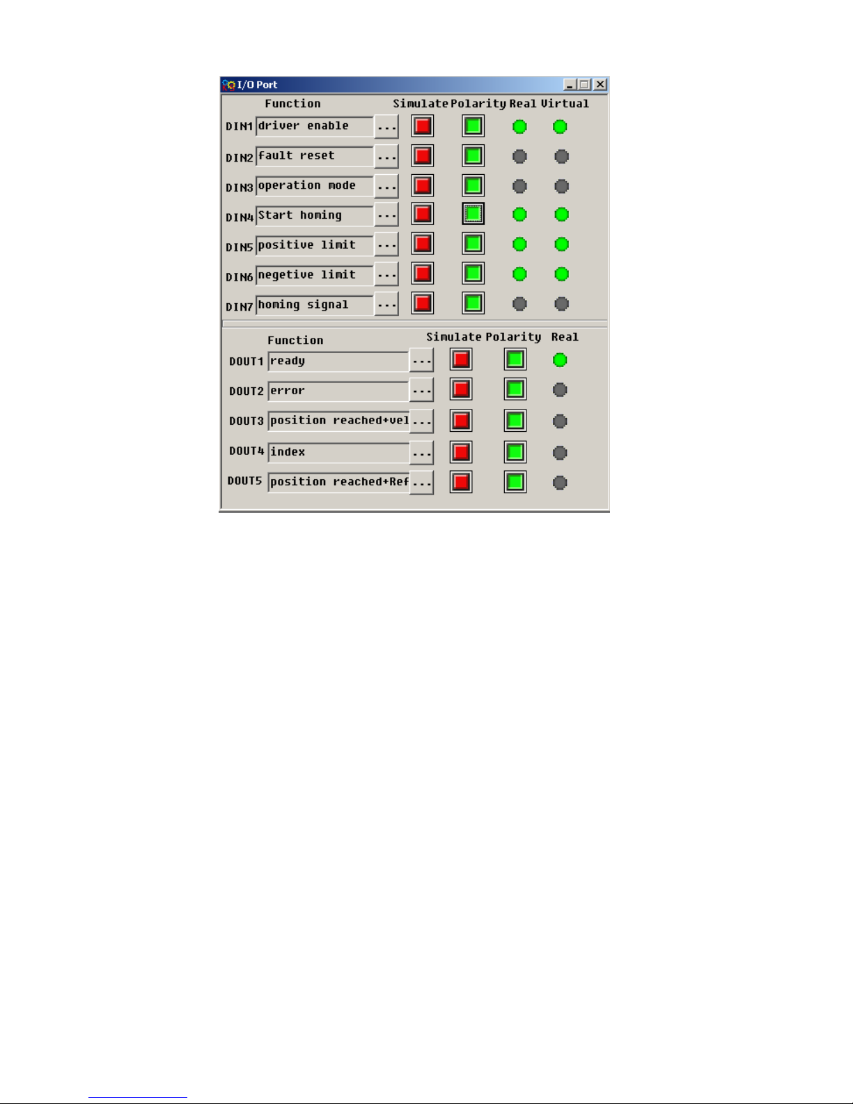
83
Note: ―Start finding the origin‖ signal is a pulse signal, requires only a rise, not need to always be on. If you
want to start next time, a rise pulse is enough.
(4). After the external find the origin, computer monitoring picture is as follows:
Page 84
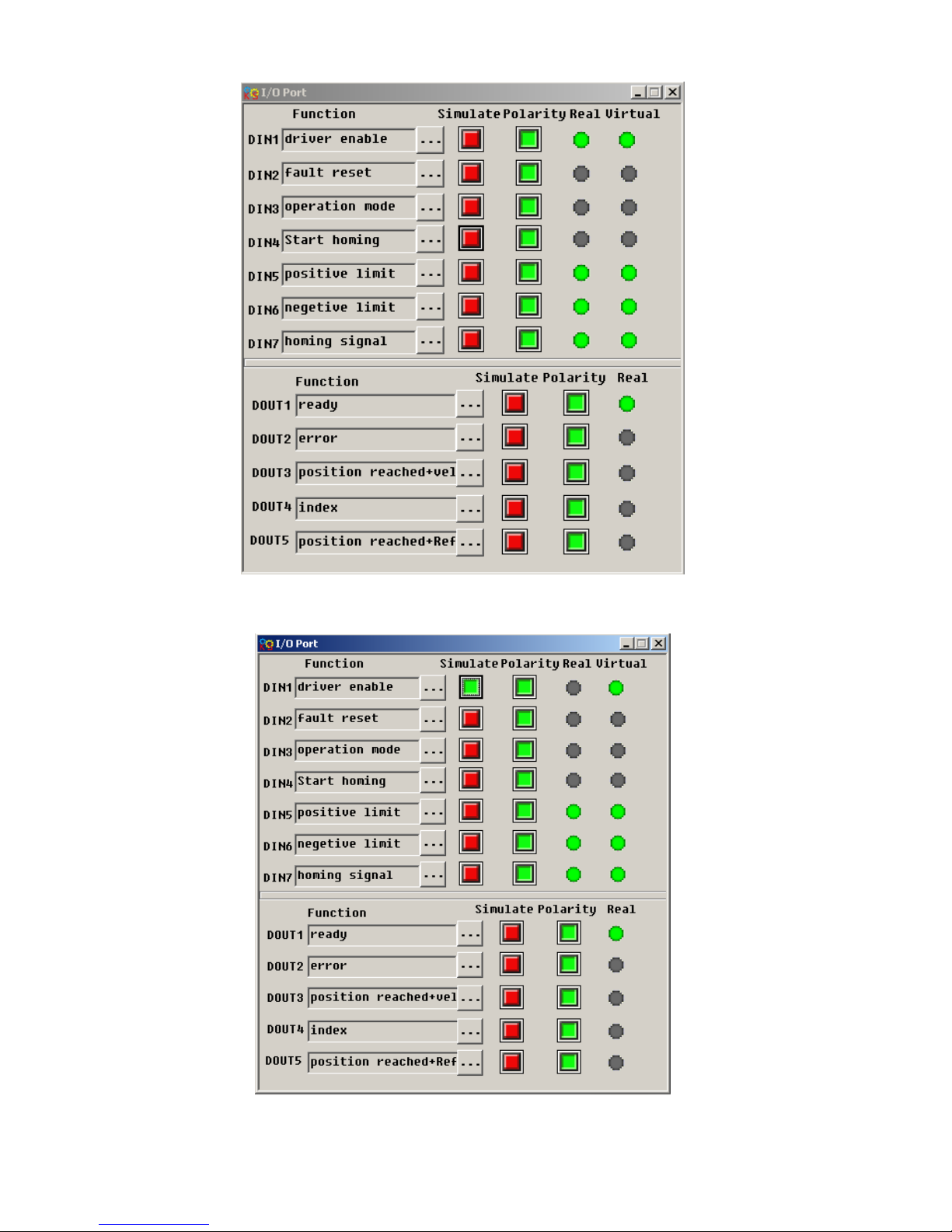
84
(5). Driver searches the Z phase signal in mode 7, and ultimately find the origin. Computer monitoring picture
is shown as follows:
In mode 7, it is default to detect z phase signal after searching the origin decline along. Computer monitoring
Page 85
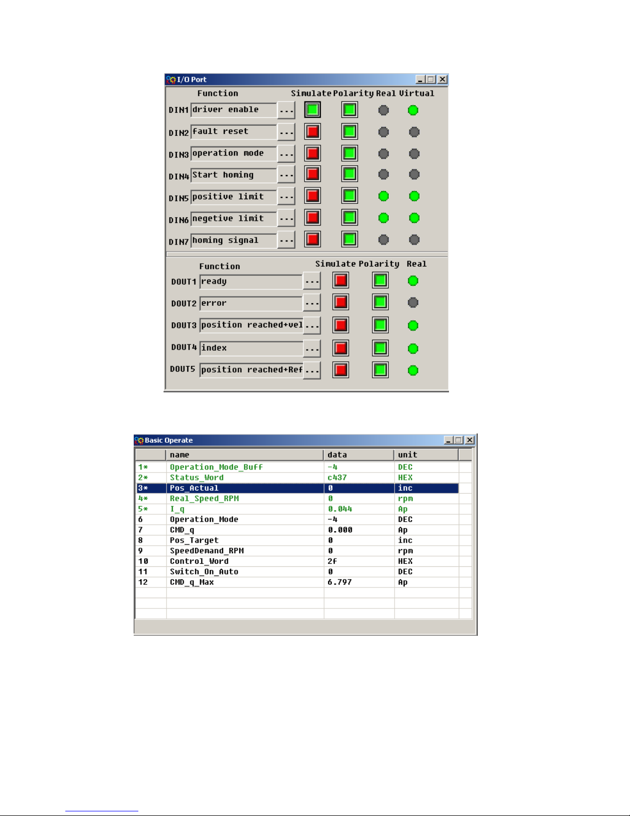
85
picture is shown as follows:
At this point, you have completed the origin search function, then the drive position is automatically set to
zero, and the current position is default to origin. Computer monitoring picture is as shown:
Page 86
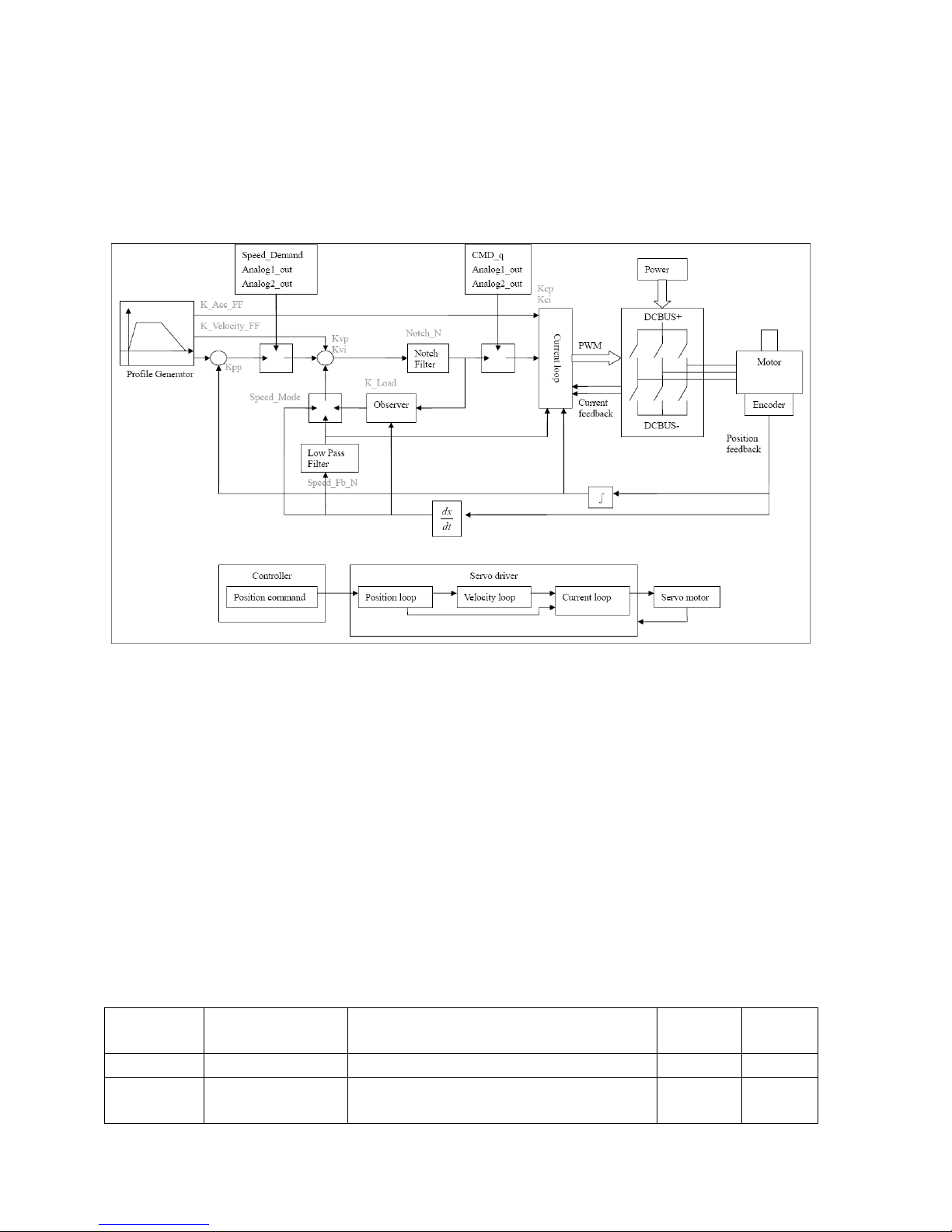
86
Chapter 8 Control Performance
8.1 Driver Performance Tuning
Fig. 8-1 Schematic diagram for control loop adjustment
As shown in Fig. 8-1, a typical servo system contains three control loops, namely, a position loop, a
velocity loop, and a current loop.
Current loops are related to motor parameters (optimal parameters of the selected motor are default for
the driver and no adjusting is required).
Parameters for velocity loops and position loops should be adjusted properly according to loading
conditions.
During adjustment of the control loop, ensure that the bandwidth of the velocity loop is at least twice of
that of the position loop; otherwise oscillation may occur.
8.1.1 Manual Adjustment
1. Parameters for velocity loop
Table 8-1 Parameters for velocity loop
Numeric
Display
Variable Name
Meaning
Default
Value
Range
d2.01
Kvp
Sets the response speed of a velocity loop
100
0~32767
d2.02
Kvi
Adjusts speed control so that the time of
minor errors is compensated
2
0~16384
Page 87
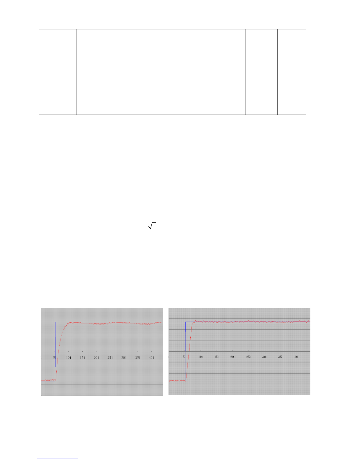
87
d2.05
Speed_Fb_N
Reduces the noise during motor operation
by reducing the feedback bandwidth of
velocity loops (smoothing feedback signals
of encoders). When the set bandwidth
becomes smaller, the motor responds
slower.
The formula is F=Speed_Fb_N*20+100.
For example, to set the filter bandwidth to
"F = 500 Hz‖, you need to set the
parameter to 20.
45 0~45
Proportional gain of velocity loop Kvp: If the proportional gain of the velocity loop increases, the responsive
bandwidth of the velocity loop also increases. The bandwidth of the velocity loop is directly proportional to the
speed of response. Motor noise also increases when the velocity loop gain increases. If the gain is too great,
system oscillation may occur.
Integral gain of velocity loop Kvi: If the integral gain of the velocity loop increases, the low-frequency intensity
is improved, and the time for steady state adjustment is reduced; however, if the integral gain is too great,
system oscillation may occur.
Adjustment steps:
Step 1: Adjust the gain of velocity loop to calculate the bandwidth of velocity loop
Convert the load inertia of the motor into the inertia Jl of the motor shaft, and then add the inertia Jr of the
motor itself to obtain Jt = Jr + Jl. Put the result into the formula:
* * _
Vc_Loop_BW Kvp *
*204800000* 2*2
pt
t
I K Encoder R
J
To calculate the bandwidth of the velocity loop
Vc_Loop_BW
according to the adjusted the gain of velocity loop Kvp, only adjust Kvi according to actual
requirements.
Adjust the impact of Kvp and Kvi, as shown in Fig. 8-2.
For the effect of Kvp adjustment, see the first to the fourth from left of Fig. 8-2. Kvp gradually increases from
the first to the fourth from left. The value of Kvi is 0.
For the effect of Kvi adjustment, see the first to the fourth from right of Fig. 8-2. Kvi gradually increases from
the first to the fourth from right. The value of Kvp remains unchanged.
Left 1
Right 1
Page 88
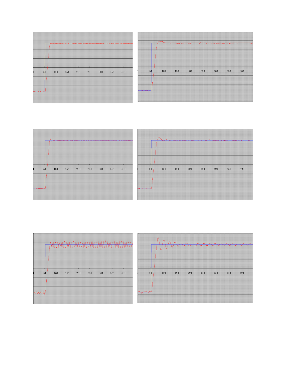
88
Fig. 8-2 Schematic diagram of gain adjustment of velocity loop
Step 2: Adjust parameters for feedback filter of velocity loop
During gain adjustment of a velocity loop, if the motor noise is too great, you can properly reduce the
parameter Speed_Fb_N for feedback filter of the velocity loop;
Left 2
Right 2
Left 3
Right 3
Right 4
Left 4
Page 89
89
however, the bandwidth F of the feedback filter of velocity loop must be at least three times of the bandwidth
of velocity loop; otherwise oscillation may occur. The formula for calculating the bandwidth of feedback filter
of velocity loop is F = Speed_Fb_N*20+100 (Hz).
2. Parameters for position loop
Table 8-2 Parameters for position loop
Numeric
Display
Variable Name
Meaning
Default
Value
Range
d2.07
Kpp
Indicates the proportional gain of the
position loop Kpp
1000
0~16384
d2.08
K_Velocity_FF
0 indicates no feedforward, and 256
indicates 100% feedforward
256
0~256
d2.09
K_Acc_FF
The value is inversely proportional to
the feedforward
7FF.F
32767~10
d0.05
Pc_Loop_BW
Sets the bandwidth of the position
loops in Hz
0
N/A
Proportional gain of the position loop Kpp: If the proportional gain of the position loop increases, the
bandwidth of the position loop is improved, thus reducing both the positioning time and following errors.
However, too great bandwidth may cause noise or even oscillation. Therefore, this parameter must be set
properly according to loading conditions. In the formula Kpp=103* Pc_Loop_BW, Pc_Loop_BW indicates
the bandwidth of the position loop. The bandwidth of a position loop is less than or equal to that of a velocity
loop. It is recommended that Pc_Loop_BW be less than Vc_Loop_BW /4 (Vc_Loop_BW indicates the
bandwidth of a velocity loop).
Velocity feedforward of the position loop K_Velocity_FF: the velocity feedforward of a position loop can be
increased to reduce position following errors. When position signals are not smooth, if the velocity
feedforward of a position loop is reduced, motor oscillation during running can be reduced.
Acceleration feedback of the position loop K_Acc_FF (adjustment is not recommended for this parameter): If
great gains of position rings are required, the acceleration feedback K_Acc_FF can be properly adjusted to
improve performance.
* * _
K_Acc_FF
250000* 2* *
pt
t
I K Encoder R
J
Note: K_Acc_FF is inversely proportional to the
acceleration feedforward.
Adjustment steps:
Step 1: Adjust the proportional gain of a position loop.
After adjusting the bandwidth of the velocity loop, it is recommended to adjust Kpp according to actual
requirements (or directly fill in the required bandwidth in Pc_Loop_BW, and the driver will automatically
calculate the corresponding Kpp). In the formula Kpp = 103*Pc_Loop_BW, the bandwidth of the position loop
is less than or equal to that of the velocity loop. For a common system, Pc_Loop_BW is less than
Vc_Loop_BW /2; for the CNC system, it is recommended that Pc_Loop_BW is less than Vc_Loop_BW /4.
Step 2: Adjust velocity feedforward parameters of the position loop.
Velocity feedforward parameters (such as K_Velocity_FF) of the position loop are adjusted according to
position errors and coupling intensities accepted by the machine. The number 0 represents 0% feedforward,
and 256 represents 100% feedforward.
3. Parameters for pulse filtering coefficient
Page 90
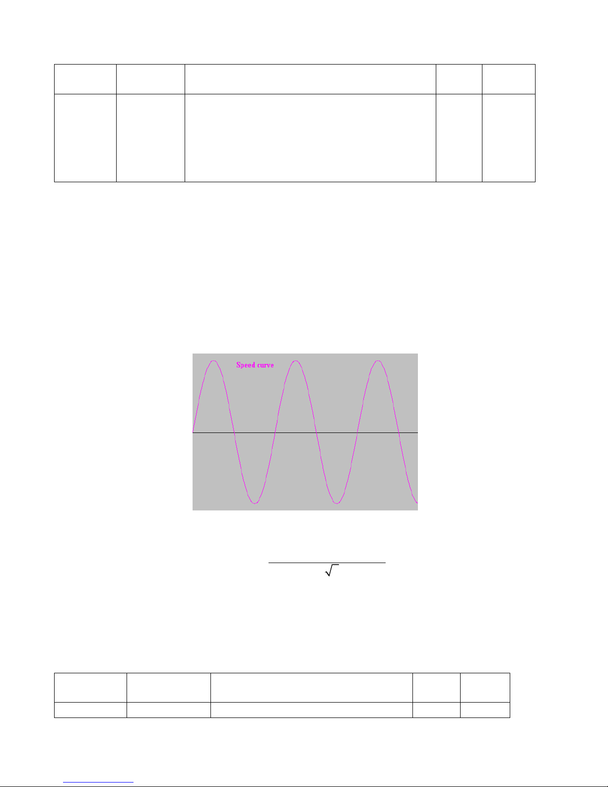
90
Table 8-3 Parameters for pulse filtering coefficient
Numeric
Display
Variable
Name
Meaning
Default
Value
Range
d3.37
PD_Filter
Used to smooth the input pulses.
Filter frequency: f = 1000/(2π* PD_Filter)
Time constant: T = PD_Filter/1000
Unit: S
Note: If you adjust this filter parameter during the
operation, some pulses may be lost.
3
1~32767
When a driver operates in the pulse control mode, if the electronic gear ratio is set too high, this
parameter must be adjusted to reduce motor oscillation; however, if the parameter adjustment is too great,
motor running instructions will become slower.
8.1.2 Auto Adjustment (Only for Velocity Loops)
Auto adjustment is only available for velocity loops (see Section 8.11 for manual adjustment of position
loops) when both forward rotation and reverse rotation of a motor are allowable, and the loadings do not
change much during the operation. You can determine the total inertia of motor loadings through gain auto
tuning, and then manually enter the desired bandwidth. The driver will automatically calculate appropriate
Kvp and Kvi values. The motion curve is in the shape of a sine curve, as shown in Fig. 8-3.
Fig. 8-3 Speed curve
K_Load represents the internal data that displays the actual inertia of the system.
* * _ *16
_
62500* 2 *
pt
t
I K Encoder R
K Load
J
In the above formula:
Ip represents the maximum peak output current in units of ―A‖;
Kt represents the torque constant of the motor in units of ―Nm/Arms‖;
Encoder_R represents the resolution of a motor encoder in units of ―inc/r‖; and
Jt represents the total inertia of the motor and loadings in units of ―kg*m^2‖.
Table 8-4 Parameters for controlling gain auto tuning
Numeric
Display
Variable Name
Meaning
Default
Value
Range
d0.06
Tuning_Start
Auto tuning starts after the variable is set to
0
/
Page 91

91
11. All input signals are ignored during
auto tuning. The variable is automatically
changed to 0 after auto tuning is completed.
Sets the variable to other values to end auto
tuning.
d0.04
Vc_Loop_BW
Sets the bandwidth of the velocity loop in
Hz. The variable can only be set after auto
tuning is performed properly; otherwise the
actual bandwidth goes wrong, which causes
abnormal working of the driver. If the auto
tuning result is abnormal, setting this
parameter may also cause abnormal
working of the driver.
Note: This parameter cannot be applied
when auto tuning is unavailable.
0
0~600
d2.17
K_Load
Indicates loading parameters
/
20~1500
0
d2.21
Sine_Amplitude
Proper increase in this data will reduce the
tuning error, but machine vibration will
become severer. This data can be adjusted
properly according to actual conditions of
machines. If the data is too small, the auto
tuning error becomes greater, or even
causes a mistake
64
0~1000
d2.22
Tuning_Scale
It is helpful to reduce the auto tuning time by
reducing the data, but the result may be
unstable.
128
0~16384
d2.23
Tuning_Filter
Indicates filter parameters during
auto-tuning
64
1~1000
Auto tuning is a process where the suitable and stable K_Load value is automatically calculated. In the auto
tuning mode, the data of numeric display is automatically switched to the real-time display mode of K_Load
data. When K_Load data gradually becomes stable, the driver automatically adjusts Kvp and Kvi data of a
velocity loop, so that the actual bandwidth of the velocity loop is 50Hz. When K_Load data becomes stable,
the driver automatically stops auto tuning operation; then you need to customize Vc_Loop_BW, representing
the desired bandwidth of the velocity ring. Finally, run the test system in the actual environment, and save the
parameters.
Precautions:
1. Auto tuning applies when both forward rotation and reverse rotation of a motor are allowable, and the
loadings do not change much during the operation. When forward rotation or reverse rotation of the
motor is not allowable on a device, it is recommended to adjust the parameters manually.
2. During auto tuning operation, pulse signals, digital input signals, and analog signals of the external
controller are temporarily unavailable, so safety must be ensured.
3. Before auto tuning operation, it is recommended to properly adjust the Kvp, Kvi and Speed_Fb_N (a
Page 92

92
feedback filter parameter) values of the velocity loop to prevent visible oscillations when the system
works in the speed mode. If necessary, adjust the data of d2.03 notch filter to inhibit resonance.
4. The time for different load tuning varies, and generally a few seconds is required. The auto tuning time
can be reduced by presetting the K_Load value to a predicted value that is close to the actual value.
5. Vc_Loop_BW can be written only after successful auto tuning, otherwise the driver may work improperly.
After you write the desired bandwidth of the velocity loop in Vc_Loop_BW, the driver automatically
calculates the corresponding values of Kvp, Kvi and Speed_Fb_N. If you are dissatisfied with low-speed
smoothness, you can manually adjust Kvi. Note that auto tuning does not automatically adjust the data of
a notch filter.
In the following circumstances, auto tuning parameters should be adjusted:
1. When the friction in a rotation circle of the motor is uneven, it is required to increase the amplitude of
d2.21 sine wave to reduce the impacts caused by uneven friction. Note that d2.21 increases when
the oscillation amplitude of the loadings increase.
2. If auto tuning lasts for a long time, initial evaluation of the total inertia is available. It is recommended
to set K_Load to an evaluation value before auto tuning.
3. If auto tuning is unstable, the stability of auto tuning increases when d2.22 increases properly, but
the time for auto tuning slightly increases.
In the following conditions, auto adjustment goes wrong. In this case, you can only set parameters manually:
1. The load inertia is featured by great fluctuation.
2. Mechanical connection rigidity is low.
3. Clearances exist in the connection between mechanical elements.
4. The load inertia is too great, while Kvp values are set too low.
5. If the load inertia is too great, K_Load data will be less than 20; if the load inertia is too little, K_Load
data will be greater than 15000.
Operational steps:
1. Step 1: Press MODE to enter Group F002. Select the object addresses ―d2.01‖, ―d2.02‖ and ―d2.05‖
respectively for initial settings, so that no obvious oscillation occurs when the system works in the speed
mode.
2. Step 2: Press MODE to enter Group F000. Select the object address ―d0.06‖, set the address to 11, and
auto tuning starts.
3. Step 3: Press MODE to enter the parameter display status. During auto tuning, the content of numeric
display is K_Load data in real time. Step 4: When K_Load data becomes stable, auto tuning is completed,
and the value of ―d0.06‖ is automatically changed to 0.
4. Step 5: You need to customize the required bandwidth of the velocity loop Vc_Loop_BW. In this case, it is
recommended to increase the bandwidth gradually, until the machine works in the optimum state. Finally,
run the test system in the actual environment and save the parameters.
8.2 Oscillation Inhibition
If resonance occurs during machine operation, you can adjust a notch filter to inhibit resonance. If
resonance frequency is known, you can directly set Notch_N to (BW-100)/10. Note that you need to set
Notch_On to 1 to enable the notch filter. If you do not know exactly the resonance frequency, you can firstly
set the max value of d2.14 current instruction to a low one, so that the oscillation amplitude is within the
acceptable range; then try to adjust Notch_N to check whether resonance disappears.
If machine resonance occurs, you can calculate the resonance frequency by observing the waveform of
the target current with the oscilloscope function of the driver.
Page 93

93
Table 8-5 Parameters for oscillation inhibition
Numeric
Display
Variable Name
Meaning
Default
Value
Ran
ge
d2.03
Notch_N
Notch/filtering frequency setting for a velocity
loop, used to set the frequency of the internal
notch filter, so as to eliminate the mechanical
resonance produced when the motor drives
the machine. The formula is F = Notch_N*10 +
100.
For example, if the mechanical resonance
frequency is F = 500 Hz, the parameter should
be set to 40.
45
0~9
0
d2.04
Notch_On
Enable or disable the notch filter
0: Disable the notch filter
1: Enable the notch filter
0
/
Page 94
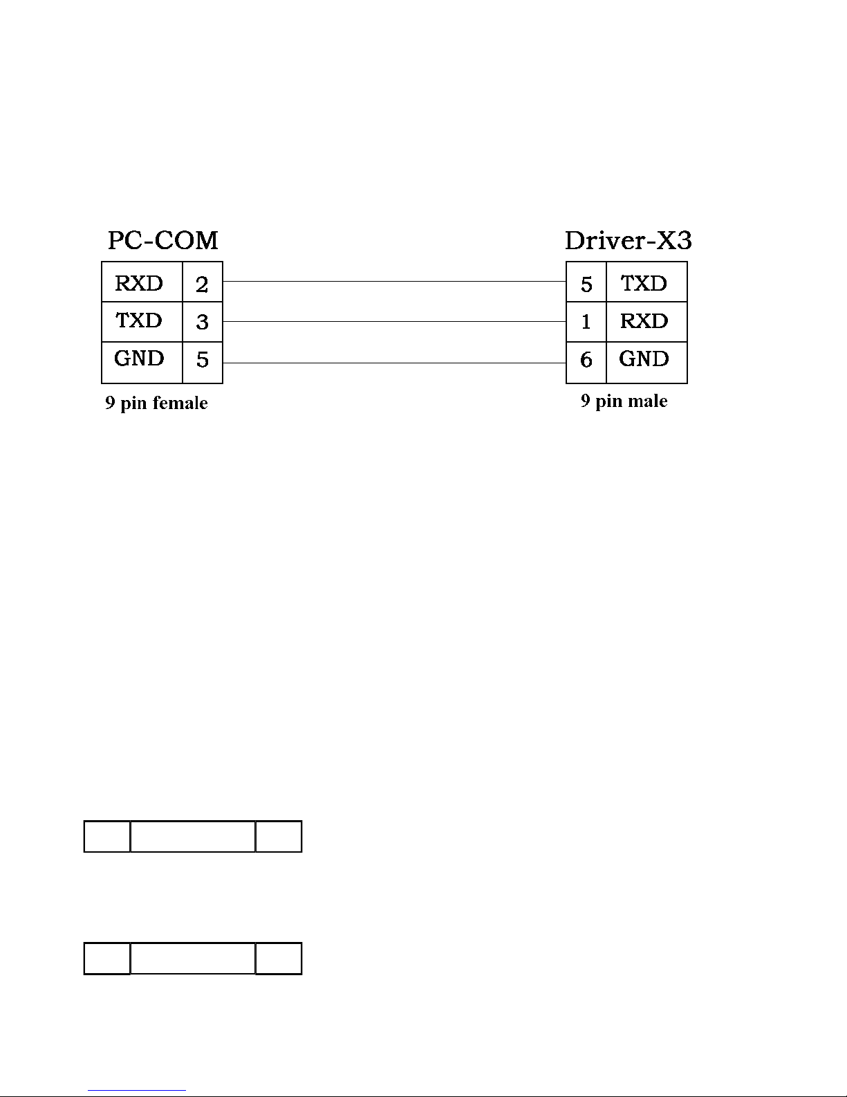
94
Chapter 9 Communication
A CD servo driver has the RS232 communication interface, which directly controls the working of the
servo driver with the operation software of a host computer. If the servo driver needs to communicate with a
Programmable Logic Controller (PLC) or other controllers via the free RS485 communication interface, an
RS232 to RS485 converter should be added on the driver side.
Fig. 9-1 Communication cables between a PC and a servo driver
9.1 Transport Protocol
The RS-232C communication of the CD servo driver strictly follows a master/slave protocol. The host
computer can send any data to CD driver. The driver configured with ID No. will calculate such data and
return a reply.
Default communication settings for the CD servo driver are as follows:
Baud rate = 38400 bps
Data bits = 8
Stop bits = 1
No parity check
This transport protocol uses a data packet with fixed length of10 bytes.
ID 8 byte data CHKS
byte 0 byte 9
The baud rate can be changed by setting d5.02, after changing the value, it is necessary to set d2.00 or d3.00
to save it and reboot the system so that it will take effect.
The transport protocol used by the RS-232 uses a data packet with fixed length of10 bytes.
ID CHKS8 byte data
byte 0 byte 9
ID is the ID No. of the slave
CHKS =-SUM(byte0,…,byte8), CHKS is the last two digits of the calculation result.
The host sends:
ID CHKS8 byte host data
byte 0 byte 9
The slave sends/The host receives:
Page 95
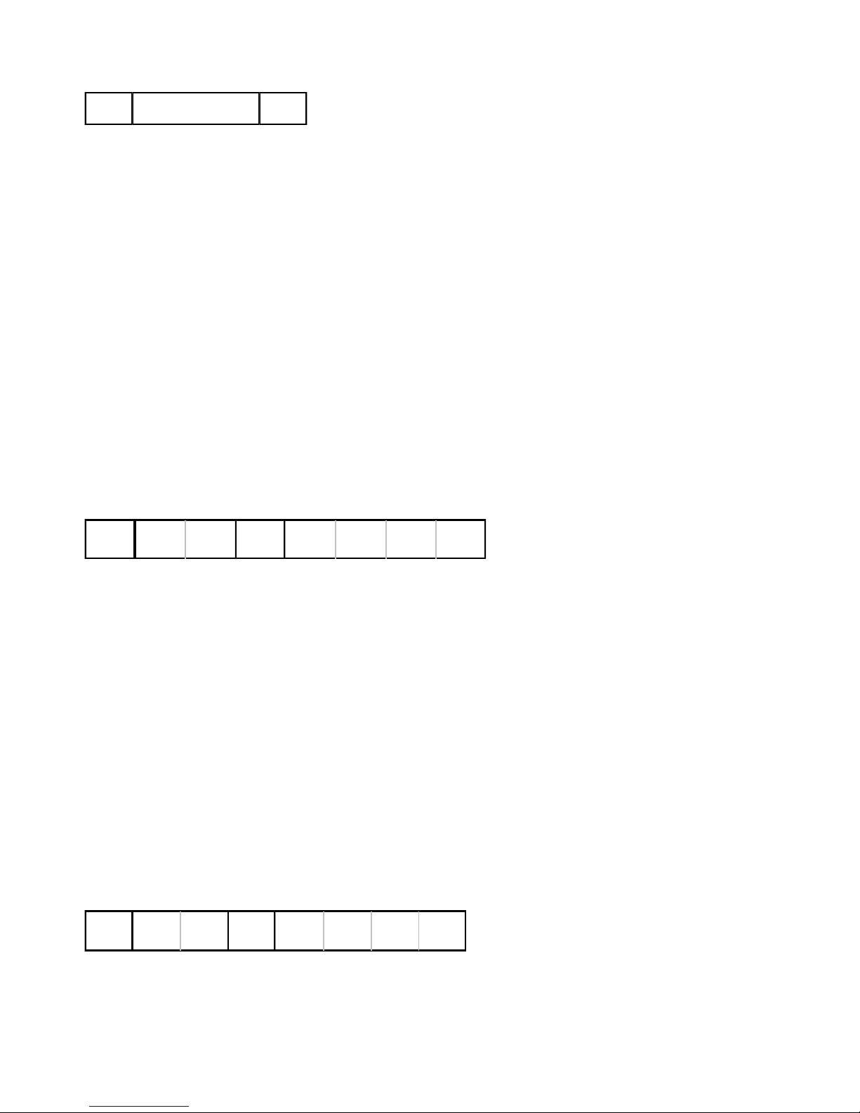
95
ID CHKS8 byte slave data
byte 0 byte 9
Note: Each 10-byte packet has its own CHKS.
If the host sends an ID not existed in the network to the CD servo driver, no CD servo driver will make a reply.
After the host sends the data correctly, the slave will find the data packets in compliance with its own ID and
check the CHKS value. If the checksum does not match, the slave will not make a response.
9.2 Data Protocol
A data protocol is different from a transport protocol. It contains 8 bytes of all 10 bytes of the above RS-232.
Definition of CD servo driver internal data complies with the CANopen international standard. All parameters,
values and functions are expressed by index and subindex.
9.2.1 Download(from Host to Slave)
Download refers to that the host sends a command to write values into the objects in the slave, and the host
generates an error message when the value is downloaded to a non-existent object.
The host sends:
CMD
byte 0 byte 1 byte 2 byte 3 byte 4 byte 5 byte 6 byte 7
INDEX
SUB
INDEX
DATA
CMD Specifies the direction of data transfer and the volume of data.
23(0x16) Sends 4-byte data (bytes 4...7 contain 32 bits)
2b(0x16) Sends 2-byte data (bytes 4, 5 contain 16 bits)
2f(0x16) Sends 1-byte data (bytes 4 contains 8 bits)
INDEX Index in the object dictionary where data should be sent
SUB INDEX Subindex in object dictionary where data should be sent
In all four bytes in data, the lower-order bits are arranged before the higher-order bits. To write 600 RPM into
―Target Velocity‖ in the slave, the unit of 2FF00910 is rpm, 600 is in decimal system, and 258 is in
hexadecimal system.Since the length of the object to be written is 4 bytes and the calculation result 02 58 has
only 2 bytes,zero shall be filled to the higher-order bits. Therefore, the final result = 00 00 02 58.
DATA: byte4=58
byte5=02
byte6=00
byte7=00
The slave answers:
RES
byte 0 byte 1 byte 2 byte 3 byte 4 byte 5 byte 6 byte 7
INDEX
SUB
INDEX
RESERVED
RES: Displays slave response:
60(0x16) Data successfully sent
80(0x16) Error, bytes 4…7 contain error cause
Page 96
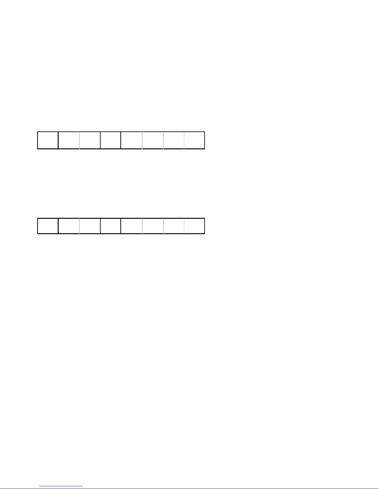
96
INDEX 16-bit value, same as that sent by the master
SUBINDEX 8-bit value, same as that sent by the master
RES Reserved for future use
9.2.2 Upload(From Slave to Host)
Upload refers to that the master sends a command to read object address in the slave and the master will
generate an error if a non-existent target address is uploaded.
The master sends:
CMD
byte 0 byte 1 byte 2 byte 3 byte 4 byte 5 byte 6 byte 7
INDEX
SUB
INDEX
RESERVED
CMD Specifies the direction of data transfer
40(0x16)
INDEX 16-bit value
SUBINDEX 8-bit subindex
RESERVED Bytes 4…7 not used
The slave receives:
RES
byte 0 byte 1 byte 2 byte 3 byte 4 byte 5 byte 6 byte 7
INDEX
SUB
INDEX
DATA
RES Displays slave response:
43(0x16) bytes 4...7 contain 32-bit data
4B(0x16) bytes 4, 5 contain 16-bit data
4F(0x16) byte 4 contains 8-bit data
80(0x16) error, bytes 4…7 contain error cause
INDEX 16-bit value, same as that sent by the master
SUBINDEX 8-bit value, same as that sent by the master
If the data contains no error, byte 4…byte 7 save the object value read from the slave, with the lower-order
bits arranged before the higher-order bits. Correct value = byte7, byte6, byte5, byte4. If there is an error, data
contained in these four types is no longer object values read from the slave.
For example:
The master sends a ―upload‖ command to the slave:
01 40 F0 2F 09 58 02 00 00 3D (This command reads target velocity 2FF00910 from the slave)
The slave answers:
01 4B F0 2F 09 58 02 00 00 32
Indicates: 01—Slave index is 1
4B – Received data contains 2 bytes, saved to byte 4…byte 5 in the 10 bytes of the response
byte4=58, byte5=02, byte6=00, byte7=00
Then, DATA= byte7 byte6 byte5 byte4 = 0258(hex)= 600 rpm
Page 97
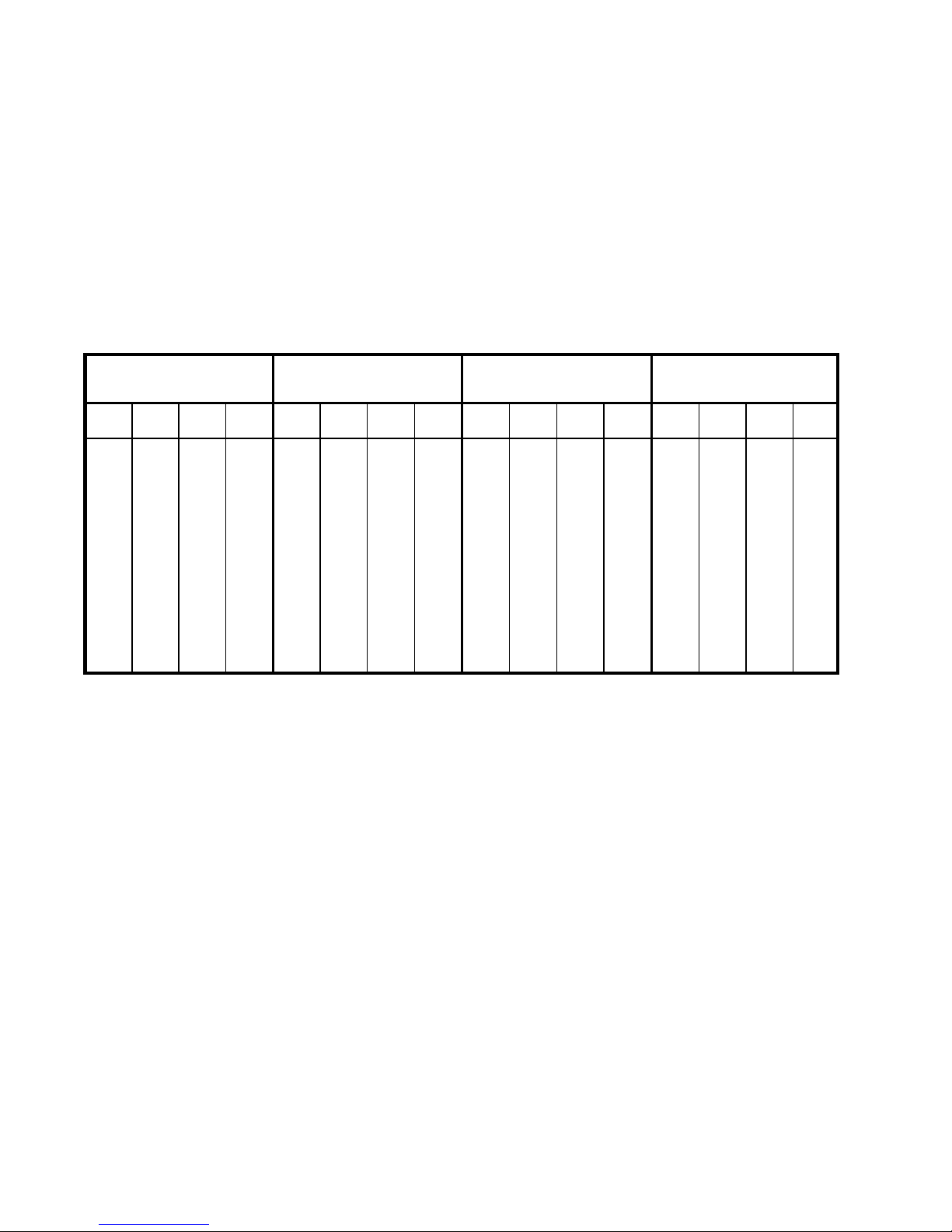
97
Chapter 10 Troubleshooting
10.1 Alarm Messages
Digital flickering on the display indicates that an alarm occurs indicating that the driver is faulty. For
details about faults, see Table 10-1 ―Fault codes‖. A code of the alarm message is represented by a
hexadecimal data, and four numeric displays appear. If the driver is faulty, the corresponding bits in the alarm
codes are set to ―1‖. For example, if an encoder is not connected, the 1
st
and 2nd bits of the faulty code are set
to ―1‖. As a result, ―0006‖ is displayed.
Table 10-1 Fault codes
1st bit in numeric display
(left)
2nd bit in numeric display
3rd bit in numeric display
4th bit in numeric display
(right)
15
14
13
12
11
10 9 8 7 6 5 4 3 2 1 0
EEPROM Error
Commutation
Reserved
Over Frequency
IIt Error
Logic Voltage
Following Error
Chop Resistor
Over Current
Low Voltage
Over Voltage
Over Temperature
Encoder Counting
Encoder UVW
Encoder ABZ
Internal
A maximum of 7 generated alarms can be stored in the driver. For details, enter the menu of Group F007.
Press Enter. The interface of faulty codes is displayed. The errors that you first discovered are those that
have occurred most recently. Press ▲ or ▼ to browse the messages of historical alarms. If the decimal point
at the lower right corner in the second bit of the numeric display is on, it indicates that the earliest alarm
message is just browsed; if the decimal point at the lower right corner in the third bit of the numeric display is
on, it indicates that the latest alarm message is just browsed.
For details on error messages, you need to access PC software via a communication port to check the
working status of the driver when an error occurs. Here are some messages of the driver for your reference:
1. Error codes;
2. Bus voltage when an error occurs;
3. Motor speed when an error occurs;
4. Motor current when an error occurs;
5. Driver temperature when an error occurs;
6. Working mode of the driver when an error occurs;
7. Accumulated working time of the driver when an error occurs;
8. Whether the current loop works when an error occurs; [0x0000 indicates that the power tube does
not work, and 0x0077 indicates that the power tube is working]
Page 98
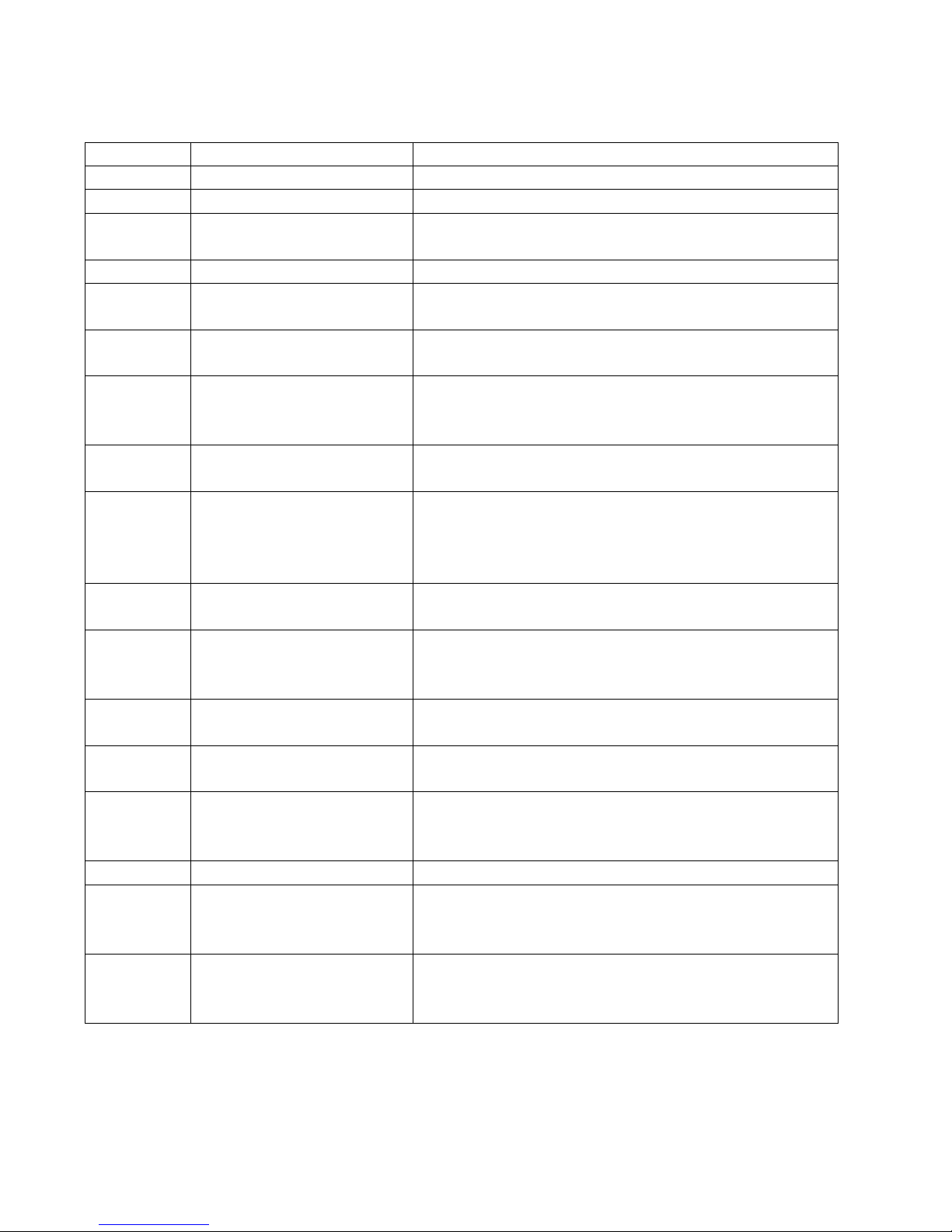
98
10.2 Alarm Causes & Troubleshooting
Alarm Code
Alarm Message
Alarm Cause & Troubleshooting
000.1
Internal
000.2
Encoder ABZ
The ABZ signal cable is disconnected. Check the cable.
000.4
Encoder UVW
The UVW signal cable is disconnected. Check the cable.
000.8
Encoder Counting
Interferences are suppressed.
000.6
Encoder Error
ABZ and UVW signals of the encoders incur error
simultaneously. Check the cable.
001.0
Over Temperature
The driver temperature exceeds 75°C. Check whether the
selected driver has enough power.
002.0
Over Voltage
The bus voltage of the driver exceeds the allowable range.
Check the input voltage, or determine whether a braking
resistor is connected.
004.0
Low Voltage
The voltage of the driver bus is below the allowable range.
Check the input power.
008.0
Over Current
The power tube in the driver is faulty, or short circuit occurs
on the phase line of the motor. Check motor wires. If the
motor works properly, it can be judged that faults occur on
the power tube in the driver.
010.0
Chop Resistor
The braking resistor or the braking components in the driver
is faulty.
020.0
Following Error
Actual following error exceeds the allowable value. Check
the feedforward value of the position loop and the maximum
allowable error.
040.0
Logic Voltage
The logic voltage is lower than 18V. Check the logic power
supply 24V.
080.0
IIt Error
The load is too high. Check the load, and calculate whether
the motor power meets the requirements.
100.0
Over Frequency
The input pulse frequency exceeds the allowable maximum
value. Check the input pulse frequency and the maximum
permissible value of the frequency.
200.0
Reserved
The driver is reserved.
400.0
Commutation
If an encoder is loose, or some faults occur during the
installation, it is suggested to return the faulty encoder to the
manufacturer.
800.0
EEPROM Error
If an internal memory is faulty, it may be caused by updated
programs, or by a faulty EEPROM loop. Return the faulty
memory to the manufacturer.
Page 99
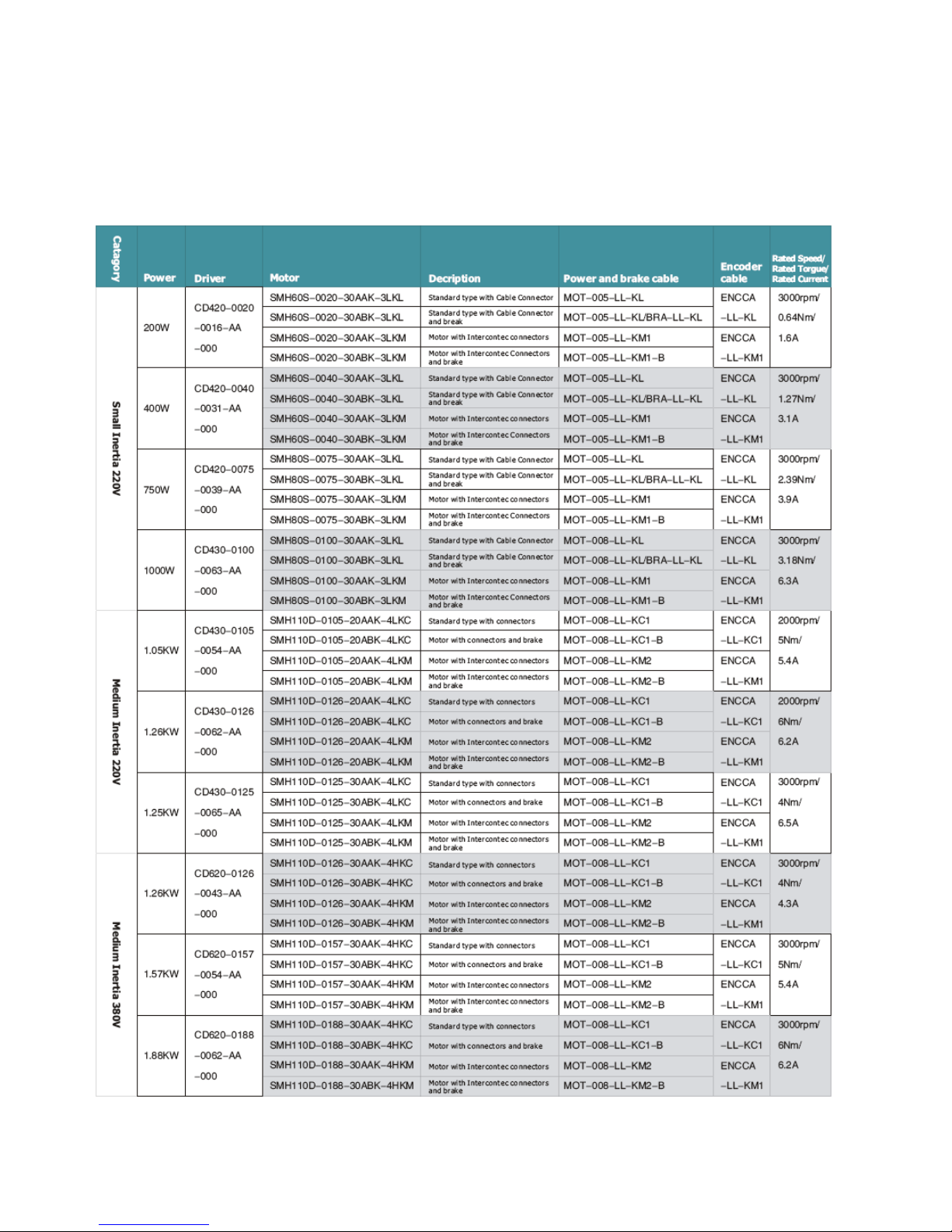
99
Chapter 11 Specification
11.1 Servo Drivers and Motors Selection Table
Page 100
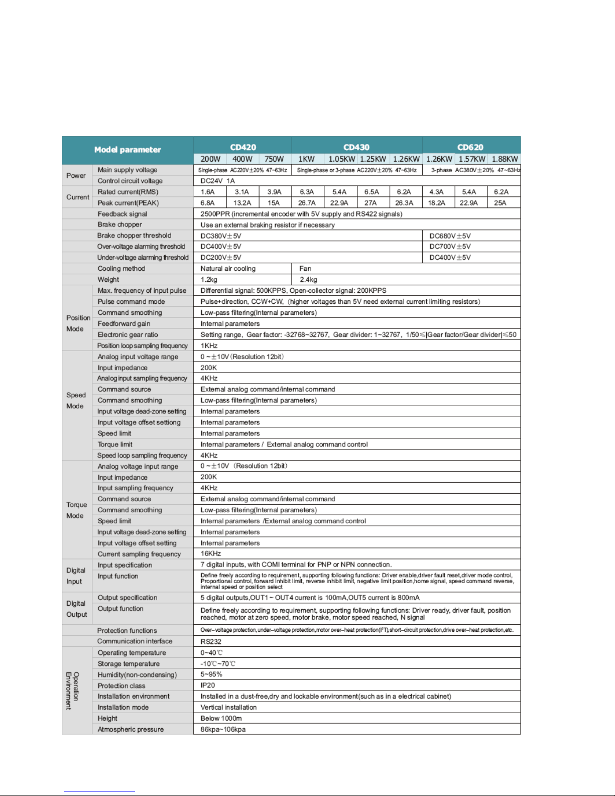
100
11.2 Servo Driver
11.2.1 Technical Specification Table for Servo Driver
 Loading...