

18.5"FHD KVM Console
(
8 Port /16 Port/24 Port /32 Port
User Manual
)
www.kinankvm.com
@all right reserved Shenzhen Kinan Technology Co., Ltd
Print date: 2019 / 11
Version: V1.0

8 Port / 16 Port / 24 Port / 32 Port User Manual
- 1 -
Contents
Overview.................................................................................................. 2
Description ........................................................................................ 2
Features ............................................................................................ 2
Structure and Size ............................................................................ 4
Rear View .......................................................................................... 5
Hardware Installation ............................................................................. 6
Rack Mounting .................................................................................. 6
KVM Installation Diagram ................................................................. 7
Operation................................................................................................. 8
LED Operating Instructions ............................................................. 10
OSD Operation ...................................................................................... 12
OSD Functions ................................................................................ 13
F1-ADM .................................................................................... 14
F2-Scan ................................................................................... 17
F3-Set ...................................................................................... 18
F4-Tool ..................................................................................... 20
F6-Edit port names .................................................................. 21
F7-Set Quick View port ............................................................ 21
F8-LOUT .................................................................................. 21
Appendix ............................................................................................... 22
Specifications .................................................................................. 22

8 Port / 16 Port / 24 Port / 32 Port User Manual
- 2 -
Overview
Description
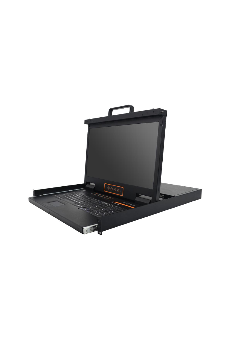
The CAT5 LCD KVM console integrates multiple-port CAT5 KVM switches in a 1U
height console. Multiple computers can be controlled from the single monitorkeyboard-mouse console.
There is no better way to save time and money than with a CAT5 console installation.
By using the CAT5 console with its sliding console to manage your installation, you
will gain below benefits: (1) eliminate the expense of purchasing separate keyboards,
monitors and mice; (2) save all the space those extra components would take up; (3)
save space that a keyboard, monitor and mouse would take with a standard KVM
switch; (4) save on energy costs; and (5) eliminate the inconvenience and wasted
effort involved in constantly having to move from on computer to another.
It is easy and fast to install the CAT5 KVM console; you just need to connect
corresponding cables to the right ports of the CAT5 KVM and its module without
software configuration.
CAT5 Console can connect multiple computers with RJ-45 connector and CAT5
connecting cables. Transmission distance is up to more than 100M, so it doesn’t need
a KVM extender.
Features
18.5” LED backlight FHD LCD TFT monitor, high brightness, high resolution
Metal 19” rack with 1U height
Ultra slim 99 keys keyboard (PS/2) with small numeric keyboard
High resolution and high flexibility with touchpad; with two function buttons and
scroll wheel, standard PS/2 port
Resolution: 1920x1080@60Hz
Switch Functions
Access and control up to 8 /16/ 24/ 32 computes
Supports Multiple systems: Windows, Linux, Mac and Sun
Convenient computer switching via front panel pushbuttons, hotkeys, OSD
menu or mouse
Hot pluggable — add or remove computers without having to power down the
switch
Auto scan feature for monitoring user-selected computers
Broadcast mode — operations simultaneously performed on all selected
computers
Keyboard and mouse emulation function.
8 Port / 16 Port / 24 Port / 32 Port User Manual
- 3 -
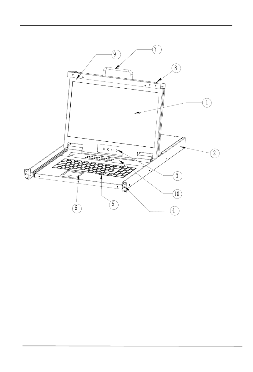
1.LCD Module
2.Rear Bracket Slot
3.OSD Controls
4.Front bracket
5.Keyboard
6.Touchpad
7.Handle
8.Release Catch
9.Display Panel
10. Switch LED
Front View
1-1.1 front view

8 Port / 16 Port / 24 Port / 32 Port User Manual
- 4 -
Structure and Size
1-1.2.
8 Port / 16 Port / 24 Port / 32 Port User Manual
- 5 -
1615141312111091 2 3 4 5 6 7 8
100V~240V AC/47~63Hz
RTN
-48V
-36V~-72V DC IN
2-2
1
3
5
2 -1
4
CONSOLE
1615141312111091 2 3
4 567
8
100V~240V AC/47~63Hz
RTN
-48V
-36V~-72V DC IN
2-2
1
3
5
2 -1
4
CONSOLE
1615141312111091 2 3
4 567
8
100V~240V AC/47~63Hz
RTN
-48V
-36V~-72V DC IN
2-2
1
3
5
2 -1
4
CONSOLE
1 2 3 4 5 6 7 8
100V~240V AC/47~63Hz
RTN
-48V
-36V~-72V DC IN
2-2
1
3
5
2 -1
4
CONSOLE
17 18 19 20 21 22 23 24
17 18 19 20 21 22 23 24
25 26 27 28 29 30 31 32
No.
Explanation
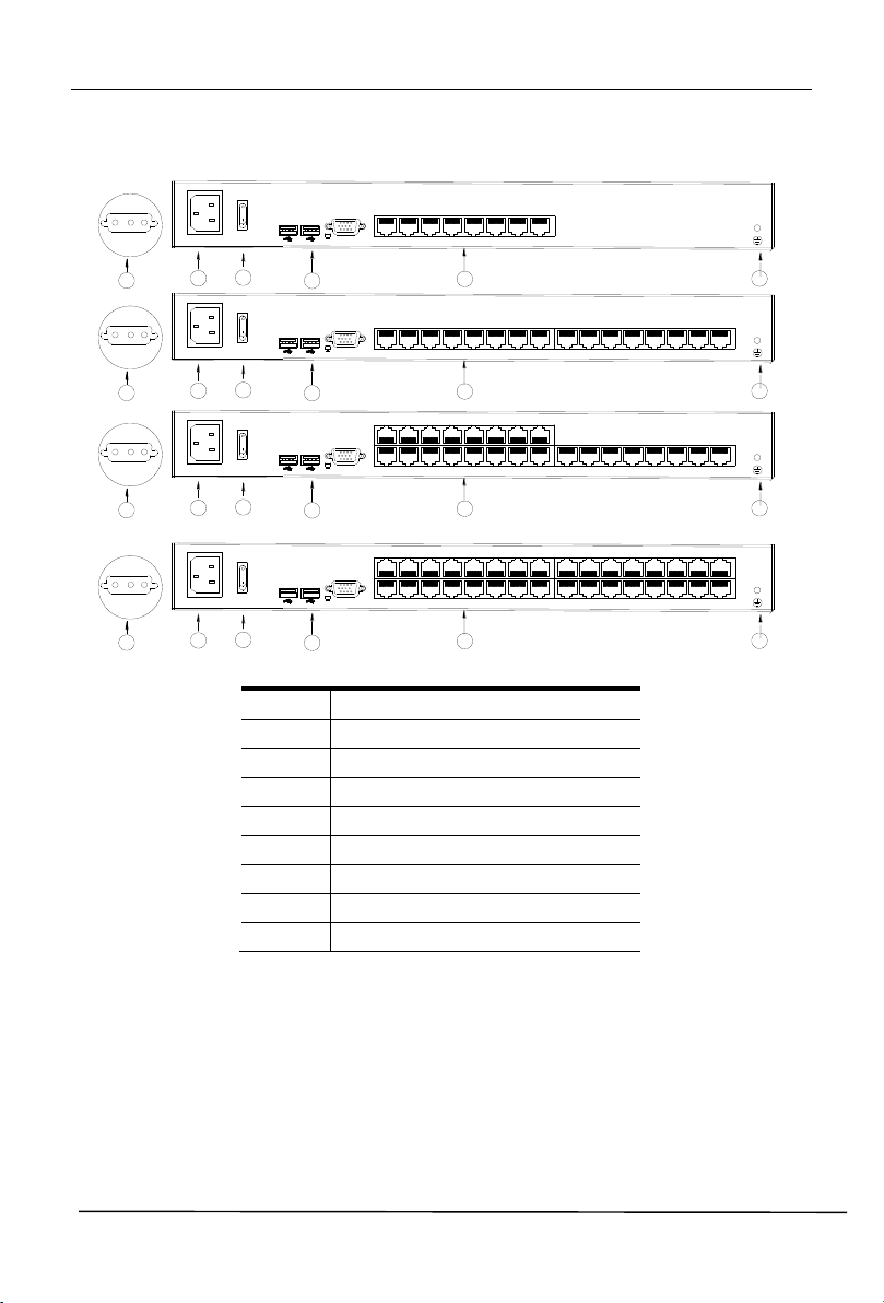
1
Ground connecting screw
2
Power input (AC or DC)
3
Power Switch
4
LAN Port
5
USB Port
6
RS485 Port
7
Monitor Port
8
PC connecting port
Rear View
8 Port / 16 Port / 24 Port / 32 Port User Manual
- 6 -
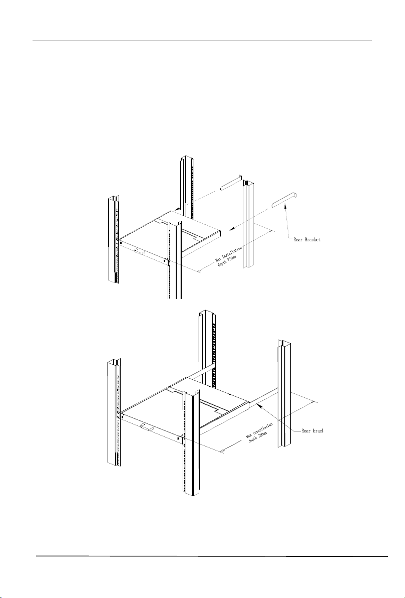
Figure 2.1 Rack Installation Diagram
Hardware Installation
Rack Mounting
A standard rack mounting kit is provided to mount the switch in a depth of 620-720mm
in a standard 19”rack.
For other mounting distance, the rear brackets need to be customized accordingly.
With one person hold the switch in place and the other person slides the L bracket
into the switch’s side mounting brackets from the front to the back, then screws the
brackets to the rack. (See below installation drawing)

8 Port / 16 Port / 24 Port / 32 Port User Manual
- 7 -
KVM Installation Diagram
1) Make sure the KVM console has been connected to the ground.( ①)
2) Connect the adapter to the KVM and the PC or server(②③)
3) Connect any available KVM port and KVM adapter with CAT5 cables.( ④)
4) Plug the female port of the power cable in the KVM power socket, and plug the
male port in the AC power port.( ⑤)
2-4 Install KVM components
Note:
1. Connect external PS/2 keyboard, mouse and monitor according to the⑥step in
2. If cascading required, please connect KVM console and KVM switch with adapter
(⑦), and Hotkey need to be different with KVM console and KVM switch. Please
check the hotkey setting with OSD below (also page 20):
2.1 Turn off Mouse Hotkey function (F4: Tool ->Mouse Hot【On】)
2.1 Keyboard hotkey setting (F3: Set -> OSD Hotkey)
【Caps Lock】 +【Caps Lock】
【F12】 +【F12】
【Ctrl】+【Ctrl】+【KVM Hotkey】

8 Port / 16 Port / 24 Port / 32 Port User Manual
- 8 -
Best Resolution :
1920x1080@60Hz
Operation
Release the release catch;
2-1.3 unlocking
*Note: The release lock can only do horizontal locking, it can’t bear any load.
Pull the KVM console all the way out until it clicks into place;
Rotate the LED module all the way back to expose the LED screen; the LED
module can be rotated up to 108°.
2-1.4 open angle of the console
The KVM makes two “beep” sounds after power on, an OSD window appears
for you to input user name and password.
8 Port /16 Port: The orange LED and LED tube are flashing before you enter
your password.
24 Port /32 Port: appears on LED tube without user name and
password.
2-1.5 password window
LED panel is powered on when the power LED is green.
Power on the computer or server after power on the KVM.
8 Port /16 Port: The LED of the connected port is green.
The factory default pass word is blank; double click “Enter “to log in.
24 Port /32 Port: There is no port LED.

8 Port / 16 Port / 24 Port / 32 Port User Manual
- 9 -
Buttons
Functions
MENU SELECT
Press this button invokes the menu function and brings up
the main menu.
EXIT/AUTO
Press this button exits the current menu and returns to the
previous menu or presses this button exits the LED OSD.
Press AUTO for automatic configuration.
SL-/SL+
Press this button moves your menu to make corresponding
adjustment.
LED state
Green :running
Red: power off or access nonstandard VESA signal
Flash green:energy saving mode or no signal
Closing the console
Close the LCD display panel and the power automatically shut down.
Push the release catch in the direction of the arrow; pull the LED panel all
the way in until it automatically locks up.
2-1.6 unlocking the console
LED OSD Configuration
The LED OSD allows you to set up and configure the LED display.
Table 2-1.7 adjust the monitor
Press AUTO if the screen migrates after power on or under other circumstances, then
the screen auto configure to its best display state.(It might can’t be adjusted to its best
state if part of the display mode is not standard VESA mode, if so return back to OSD
menu to RESET, then it will back to normal.
We suggest our customers to set up the display mode at 1920x1080, refresh rate at
60Hz.

8 Port / 16 Port / 24 Port / 32 Port User Manual
- 10 -
No.
Components
Function
1
1-16
Switching freely from port 1 to port 16
Reset
Press 【1】and 【2】 at the same time for three
seconds resets the keyboard and mouse
Scan
Press【7】 and【8】at the same time for three
seconds enters the auto scan mode.
Brightness
Press【3】 for three seconds enters brightness
adjusting mode.
33 are flashing on the LED tube.
Then press 【5】,【6】to adjust.
Press【3】exits or waits for five seconds and it will
auto-exit.
Definition
Press 【4】 for three seconds enters definition
adjusting mode.
44 are flashing on the LED tube.
Then press 【5】,【6】to adjust.
Press 【4】 exits or waits for five seconds and it
will auto-exit
Initialize
Press 【6】 for three seconds will initialize the
brightness and definition of each port.
2
Port Selection
Buttons & LEDs
Indicator LEDs are built into the switches, the
online LED light is on the left and the selected
LED light is on the right.
1. An online LED light (green) indicates that the
KVM has connected to its corresponding
computer and power on.
2. A selected LED light (orange) indicates that the
computer attached to its corresponding port is up
and running.
3
Station ID
Display the current port
LED Operating Instructions
Figure 3.1 LED front views

8 Port / 16 Port / 24 Port / 32 Port User Manual
- 11 -
No.
Components
Function
1
0~9 +Enter
Switching from port 1 to port 32
Port 8 : If you want to switch to Port 8, press【8】,
and the LED light displays , then press “Enter”,
you will come to Port 8.
Port 32: If you want to switch to Port 32, press【3】
and【2】, the LED light displays , and then press
“Enter”, you will come to Port 32.
2
(+, -)
Adjust Brightness
Press , the LED light blinking with , and then
press “+” and “–“to adjust the brightness.
3
(+, -)
Adjust Definition
Press , the LED light blinking with , and then
press “+” and “-“to adjust the definition.
4
Station ID
Display the current port
Figure 3.2 32 Port LED front views

8 Port / 16 Port / 24 Port / 32 Port User Manual
- 12 -
move: port selection
single click: port switch
double click:appear OSD menu
single click:exit OSD menu
single click:port switch
OSD Operation
Double click the right button of the mouse or double click hotkey【Scroll Lock】 to
invoke below OSD main menu. You can customize the OSD hotkeys; find more
details in OSD function instructions.
To access the OSD menu through keyboard:
2. Press any key from 【0-9】to enter any port of current station
To access the OSD menu through mouse:
*Note: Operate via keyboard after invoke the OSD menu via the touchpad.
1.In the submenus that appears, moving the highlight bar to your selected
port and then press Enter.

8 Port / 16 Port / 24 Port / 32 Port User Manual
- 13 -
Menu
Keys
Submenu/Explanation
ADM
F1
Set User login-Set User login account and password
Set accessible-Set access permissions
BRC Mode -monitor multiple computers at the same
time
Load Default-reset the menu to the original factory
default settings
Scan
F2
All-Lists all the ports on the installation
Power On-lists only powered on ports that have
attached computers.
Quick View-Lists only the ports that have been selected
as Quick View ports
Set
F3
Auto Scan-set scanning time period
Port ID-set how long a port displays on the monitor
OSD Hotkey-set OSD hotkeys
Lout Time off- to set the time out value
Tool
F4
Reset RGB-Press Enter reset RGB
Beeper【On】-press Enter switch Bee sounds
Mouse Hot 【 On】 -press Enter to close touchpad
operating on OSD.
Restore Values-press Enter restore the current user
default value.
About KVM- press Enter shows the KVM version
Edit
F6
Edits port names
QV
F7
Start or close Quick View
Lout
F8
Log out/lock the KVM
Exit
Esc
Press this key exits OSD menu
Scroll Lock
Press this key exits OSD menu
Num Lock
Press this key exits OSD menu
OSD Functions
Table 1.5
The display screen will be distorted if the CAT5 cable is too long, for this case, you
can adjust according to below steps:
1.Press【+】and ADJ FOCUS will pop up, then press【+】,【-】to adjust definition.
2.Press【,】 and ADJ BRIGHT will pop up, then press【,】, 【.】 to adjust brightness.

8 Port / 16 Port / 24 Port / 32 Port User Manual
- 14 -
Operating instructions
1) Press【F1】or 【←】【 →】enters the
F1 submenus.
2) Press 【↑】【 ↓】moves the highlight
bar to select the submenu.
3) Press 【Enter】 selects and exits
ADM menu.
4) Press【Esc】cancels the operation
and exits ADM menu.
Enter
F1-ADM
Menu Overview
Menu Explanation
1. Set User Login—Press [Enter] selects Set User Login and a screen as below
diagram 4-1.1 appears:
One administrator and four users account can be set (the account and the password
are no more than 16 characters)
Diagram 4-1.1 Diagram 4-1.2
Note:You can set up an account and password according to diagram 4-1.2, then
“ User setup ok” pops up showing that you have done your set,“ and if
“Password Not Match “pops up, you need to type in your password again
as you did in your first type.

8 Port / 16 Port / 24 Port / 32 Port User Manual
- 15 -
Menu
Explanation
FULL
Full access function to the station and can do any
operation to the ports
VIEW
Read only function, you can only read the port but
you can’t operate it if set this function.
NULL
If you set this function, the port will be not displayed
on the user’s OSD menu
2. Set Accessible—press [Enter] to select Set Accessible, then below menu appears:
(diagram 4-1.3)
Diagram 4-1.3
Note:The administrator always has full access to all the ports.
Diagram 4-1.4 Diagram 4-1.5
E.g.: 1) If you want to set access permission of [User1], press【Space】to select the
permission options you need to set.
2) [User1] log in OSD menu, below diagram 4-1.5.

8 Port / 16 Port / 24 Port / 32 Port User Manual
- 16 -
【F1】->BRC Mode OFF
->[Enter] ,enter the main
menu, all symbols turn
into speaker symbol(diagram
4-1.8 )
3. BRC Mode Off - Press [Enter] to enter the BRC mode, enter the main menu,
press 【F7】 to add or delete a port that need broadcast function. When BRC mode
is effect, a speaker symbol appears in QV column. (See below diagrams).
While BRC mode is in effect, we can synchronous operate multiple computer ports.
Note: While BRC mode is in effect, the mouse is forbidden to use.
Diagram 4-1.6 Diagram 4-1.7
1)Open BRC mode
【F1】->BRC Mode OFF-> [Enter] -->BRC Mode ON (diagram 4-1.6)
2) Open the port that need broadcast function
Press【↑】【↓】key—>select the port that need broadcast function 【F7】a
speaker symbol appears in the QV column which shows the port has entered
broadcast mode.
3) Close the broadcasting port
press【↑】【↓】key—>select the port 【F7】exit BRC mode and the speaker
symbol disappears in QV
4) Exit BRC mode
Invoke OSD main menu 【F1】->BRC Mode ON -> [Enter] --> BRC Mode OFF,
KVM exit BRC mode (diagram 4-1.8)
Diagram 4-1.8
4. Load Default--- press [Enter] to select the submenu, all the set values are restoring
to original factory default settings.

8 Port / 16 Port / 24 Port / 32 Port User Manual
- 17 -
Submenu
Explanation
All
Use this function to scan all ports according to the set
scanning interval.
Power On
Use this function to scan all signal ports with
according to the set scanning interval.
Quick View
Use this function to scan all ports with quick view
symbols according to the set scanning interval.
Operating instruction
1) Press【F2】or 【←】【 →】enters
the F2 submenus.
2) Press 【↑】【 ↓】moves the highlight
bar to select the submenu.
3) Press【Enter】selects and exits
Scan menu.
4) Press【Esc】cancels the operation
and exits SCAN menu.
F2-Scan
Menu Overview
Menu Explanation

8 Port / 16 Port / 24 Port / 32 Port User Manual
- 18 -
Submenu
Default value
Auto Scan
5S(effective range 5-99)
Port ID
0S: not display the port ID
1-98S: display the seconds, maximum 98s
99S: permanent display
OSD Hotkey
【Scroll Lock 】+ 【Scroll Lock 】
【Caps Lock】 +【Caps Lock】
【F12】 +【F12】
【Ctrl】+ 【Ctrl】+ 【KVM Hotkey】
Lout Time off
0: off
01-99M:set the screen saver timeout, it is
automatically log out if the current operator
is no longer operate for a while, then the
KVM will be locked and you need to enter
user name and password to operate again
Operating instructions
1) Press【F3】or 【←】【 →】enters the
F3 submenus.
2) Press 【↑】【 ↓】moves the highlight
bar to select the submenu.
3) Press【Enter】selects and exits Set
menu.
4) Press【Esc】cancels the operation
and exits Set menu.
F3-Set
Menu Overview
Menu Explanation

8 Port / 16 Port / 24 Port / 32 Port User Manual
- 19 -
Function
Operating
Function description
Switching port
+2 number k
eys
Eg.: switch to port 4 by hotkeys
【L_Ctrl】+【L_Ctrl】+【0】+【4】
+ F1~ F8
Skip ports from 1-8
Invoke
OSD main menu
+ “space ”
This allows you to invoke OSD main
menu(see OSD menu operation)
Operating instruction
1. Press【F3】and move the highlight bar with【↓】 to select “OSD
Hotkey ”submenu. Press 【Enter】and below screen appears:
2. KVM default hotkey:【Scroll Lock】
OSD Hotkey Operation
Select the“【Ctrl】【 Ctrl】 +【KVM Hotkey】 “ and press【Enter】, and then the 【Ctrl
hotkey is available in this hotkey mode, the mouse hotkey can't enter the OSD menu.
Invoke hotkey:double click 【L_Ctrl】 + the corresponding function key

8 Port / 16 Port / 24 Port / 32 Port User Manual
- 20 -
Submenu
Instruction
Reset RGB
Restore the video signal to the default value.
Beeper【On】
The beeper can be turned on or off with this function.
Mouse Hot【On】
To open and close the mouse with this function.
We can’t operate the OSD when it is【Off】.
Restore Values
Restore to original factory default values.
About KVM
It shows the KVM version information.
Operating instructions
1) Press【F4】or 【←】【 →】enters
the F4 submenus.
2) Press 【↑】【 ↓】moves the highlight
bar to select the submenu.
3) Press【Enter】 selects and exits
Tool menu.
4) Press 【Esc】cancels the operation
and exits Tool menu.
F4-Tool
Menu Overview
Menu Explanation

8 Port / 16 Port / 24 Port / 32 Port User Manual
- 21 -
Select ports with【↑】【↓】keys;
Press【F7】 to include current port
as Quick View, then an arrowhead
appears in the QV column to
indicate so;
Note:
Press 【F7】 to cancel the QV symbol
if the current port has already have a
QV arrowhead symbol in its QV column;
if you want to cancel all the QV function,
press Restore Values under 【F4】:Tool.
(The port name restores to default
setting at the same time.)
Select the port with【↑】【↓】 key;
Press F6 and key in the new name
or modify the old one, then press
Enter to save the name and exit
editing.
Press 【Esc】to cancel and exit the
editing.
Note:
The NAME characters include:
All alpha characters: A-Z
All numeric characters: 0-9
Default value: SYSTEM
F6-Edit port names
F7-Set Quick View port
F8-LOUT
Press【F8】exits the OSD main menu and fully exits current port, then the log
in window appears:
Users must log in all over again to regain access to the OSD.

8 Port / 16 Port / 24 Port / 32 Port User Manual
- 22 -
Model
LC2808
LC2816
LC2824
LC2832
Computer
connections
Direct 8 16
24
32
Max
256
512
768
1024
Port emulation
Keyboard,
mouse
PS/2, USB
LCD monitor
LCD model
FHD TFT
View area
18.5”
Optimum
resolution
1920×1080@60Hz
Display color
16.7 M
Brightness
500cd/m² (T y p)
Contrast ratio
1000 : 1 (T y p)
Pixel pitch(mm)
0.213(H) × 0.213(W)
Mouse
X/Y resolution
>1000 points / inch, (40 points/mm)
Touchpad with
trackball
Eliminates the need for an external mouse
Keyboard
99 keys (82 keys main keyboard +17
independent small number pad)
Port selection
Front panel pushbuttons, hotkeys, OSD menu
Input power
100V- 240Vac , 50-60Hz , <1.5A
Power consumption
30W
31W
32W
33W
Operating temperature
0 — 40 ℃
Store temperature
-20 — 60 ℃
Humidity
0~80% RH, non-condensing
Net weight
11.5kg
11.5 kg
11.7kg
11.7kg
Product dimension (W × D × H)
448mm×560mm×42.5mm
Package dimension (W × D × H)
765mm×615mm×185mm
Optional power input
-36V~ -72V DC
Appendix
Specifications
 Loading...