

KinAn HT2808, HT2824, HT2832, HT2816 User Manual

Matrix KVM over IP Console
(8 Port /16 Port/24 Port/32 Port)
User Manual
www.kinankvm.com
@all right reserved Shenzhen Kinan Technology Co., Ltd
Print date: 2019 / 12
Version: V1.3

8 Port /16 Port/24 Port/32 Port User Manual
Table of Contents
1. Product Overview ..................................................................................................... 2
1.1 Introduction ................................................................................................. 2
1.2 Features ...................................................................................................... 2
1.3 Appearance ................................................................................................. 4
2. Installation and Start-up ............................................................................................ 6
2.1 Rack Mounting ............................................................................................ 6
2.2 Install KVM Components ............................................................................ 7
2.3 Opening the Console .................................................................................. 8
2.4 Closing the console ..................................................................................... 9
3. LED Operation ..................................................................................................... 10
3.1 LED Functions .......................................................................................... 10
3.2 Operating the Monitor ............................................................................... 12
3.3 Key Combination Function ........................................................................ 13
4. User Interface Operation ......................................................................................... 14
4.1 User .......................................................................................................... 15
4.2 System ...................................................................................................... 19
4.3 Security ..................................................................................................... 21
4.4 Maintenance ............................................................................................. 23
5. Remote Control ...................................................................................................... 24
5.1 Configure the Target Server ...................................................................... 24
5.2 Remote WEB Interface Settings ............................................................... 26
5.3 Log in ........................................................................................................ 29
5.4 Video Control Interface Menu ................................................................... 30
6. IP Menu Option ................................................................ ................................ ... 36
6.1 User Management .................................................................................... 36
6.2 System Settings ........................................................................................ 41
6.3 Safety Management .................................................................................. 43
6.4 System Maintenance ................................................................................ 44
7.Appendix ................................................................................................................ 46
7.1 Specifications (18.5”) ................................................................................ 46
7.2 Grounding Requirements .......................................................................... 47
- 1 -

8 Port /16 Port/24 Port/32 Port User Manual
1. Product Overview
1.1 Introduction
The IP-based KVM (IP-KVM) redirects the local keyboard, mouse and video data to a remote
management console. The operator can safely manage one or many computers locally at
the server site or remotely via a standard internet browser. Securely gain BIOS level access
to systems for maintenance, support or failure recovery over the internet.
The IP-KVM console integrates multiple KVM switches in a 1U height console. It can control
multiple computers with a set of devices including monitor, keyboard and mouse; saving
cost and space by consolidating the hardware to a single device.
The IP-KVM console is fast and easy to install. Simply connect corresponding cables to the
correct ports of the KVM and its module without software configuration. Connect multiple
computers with compact RJ-45 connectors and CAT5e/6/7 cables, transmitting distance is
up to 100M.
1.2 Features
Hardware
18.5” TFT LCD monitor, high definition and high resolution
Rack-mountable in a 1U EIA system rack
Full size keyboard with integrated number pad
Trackball eliminates the need for a separate, external mouse
Local Console
Control up to 8 / 16/ 24 / 32 computers
Support 1 local user and 1 remote user, port share mode allows local and remote
users to gain access to a server simultaneously
Easy-to-use switching by browser-based UI interface, hotkeys and pushbuttons
Support servers with VGA port
Multiplatform client support (Windows, Linux, Unix, Mac, Solaris (Sun), Redhat,
Ubuntu
Supports a graphical interface for intuitive and convenient human-computer
interaction- local resolution is up to 1920 x 1080@60Hz
Supports mouse synchronization mode-automatically synchronizes the local and
remote mouse movements
Video synchronization with local console - EDID information for local console
display can be stored in the host module for video resolution optimization
- 2 -

8 Port /16 Port/24 Port/32 Port User Manual
Keyboard and mouse emulation to ensure the normal booting
Auto scan feature for monitoring user-selected computer
Hot pluggable – add or remove computers without having to power down the
switch
Remote Console
Adaptive 10 / 100 / 1000 Mbps network
WEB browser-based Or KVM_Clients remote management
BIOS-level access
Video quality and video tolerance can be adjusted to optimize data transfer
speed, up to 30 FPS
Full screen or scalable video display
Remote users and local users can control the same server synchronously
Support AES / DES / 3DES encryption
Support audit function-allows the administrator to audit the device through the
system log and operation log
Exit Macros support
Configurable user and group permissions for server access and control
Supports firmware upgrade
- 3 -

8 Port /16 Port/24 Port/32 Port User Manual
1. LED Monitor
2. Rear Bracket Slot
3. LED OSD Controls
4. Front Bracket
5. Keyboard
6. Touchpad
7. Handle
8. Release Catch
9. Display Panel
10. Switch LED
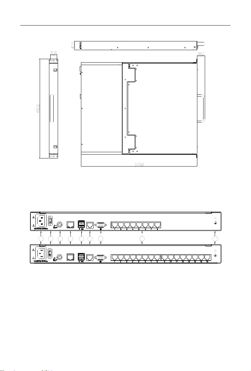
1.3 Appearance
Front View
Figure 1.1 Front view
- 4 -
8 Port /16 Port/24 Port/32 Port User Manual
8
LAN
RS485
LAN
RS485
7
6
54
232 1
1. Ground Screw
2. Power Input (AC/DC)
3. Power Switch
4. LAN Port
5. USB Port
6. RS485 Port
7. Monitor Port
8. PC Connecting Port
Structure and Size (18.5)
Figure 1.2 18.5” console size dimensions
Rear View
Figure 1.3 Rear view
- 5 -

8 Port /16 Port/24 Port/32 Port User Manual
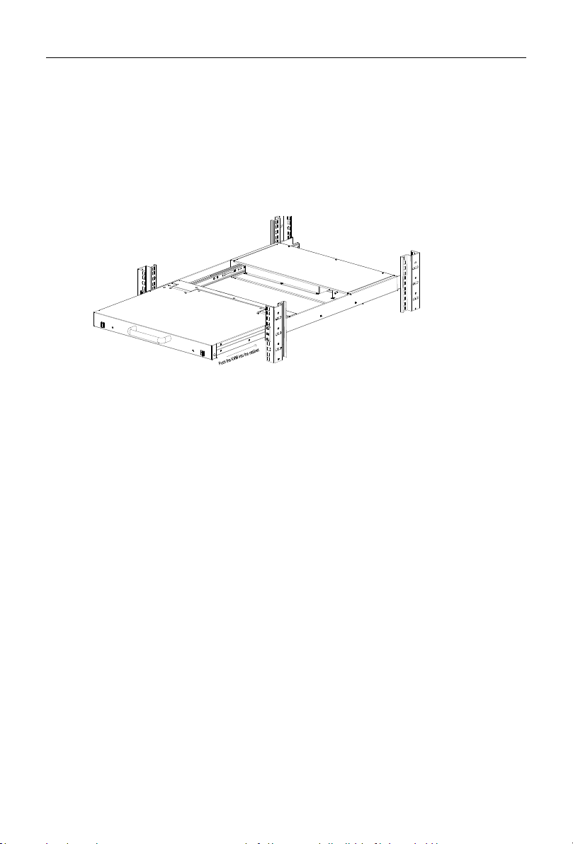
Figure 2.1 Rack Installation Diagram
2. Installation and Start-up
2.1 Rack Mounting
A standard rack mounting kit is provided to mount the switch in a depth of 620-720mm (18.5”)
in a standard 19” rack. For other mounting distances, the rear brackets need to be
customized accordingly. With one person hold the switch in place, the other person slides
the L bracket into the switch’s side mounting brackets from the front to the back, then screws
the brackets to the rack (see below installation drawing).
- 6 -
8 Port /16 Port/24 Port/32 Port User Manual
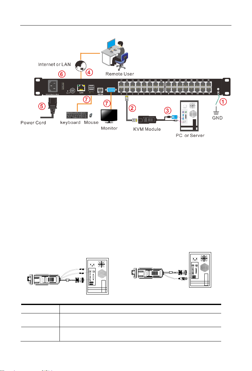
PS/2 CPU module
USB CPU module
Components
Functions
Green
indicates that the KVM has connected to its corresponding
computer and power on.
Orange
indicates that the computer attached to its corresponding
port is up and running.
2.2 Install KVM Components
Figure 2.2 Installation diagram
Installation Steps:
1. Make sure the KVM console has been connected to the ground.
2. Connect the KVM adapter to the PC or Server.
3. Connect the KVM adapter to the KVM port with a CAT5 cable.
4. You can remote control the KVM switch via IP.
5. Using power adapter to connect the KVM into 220V AC power supply.
6. Power on the switch
7. Connect the external keyboard, mouse and monitor (optional)
Module Explanation
- 7 -
8 Port /16 Port/24 Port/32 Port User Manual
UNLOCK
UNLOCK
UNLOCK
UNLOCK
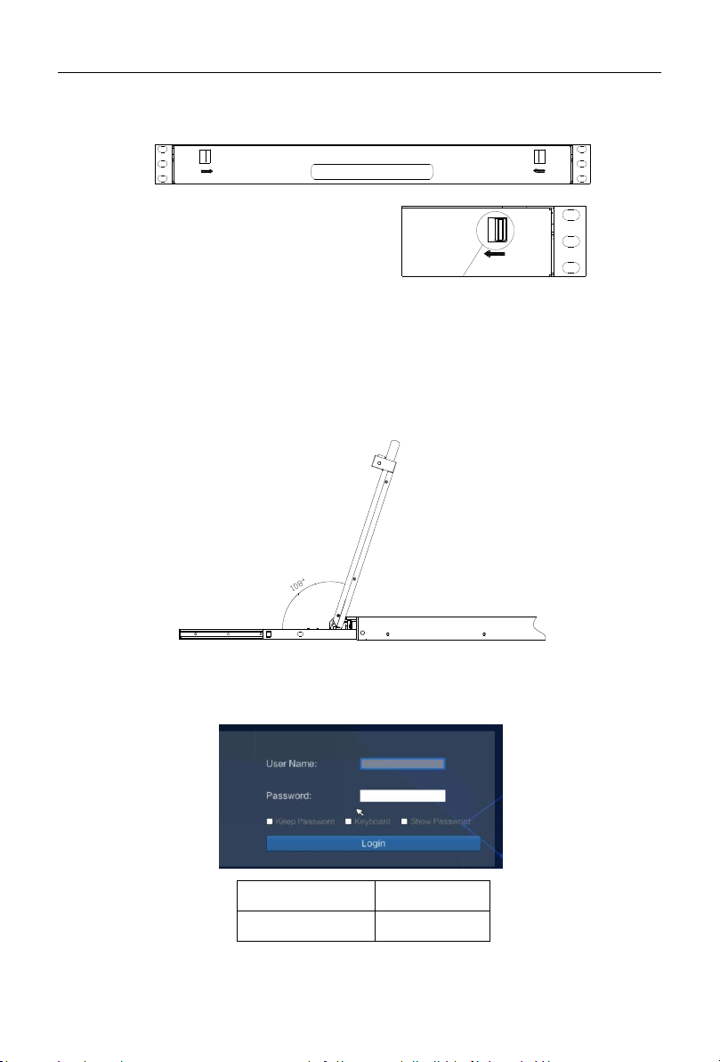
Best Resolution :
1920x1080@60Hz
User Name:
admin
Password:
admin
2.3 Opening the Console
1. Release the release catch;
Figure 2.4 Unlocking
Note: The release lock can only do horizontal locking, it doesn’t bear any load.
2. Pull the KVM console all the way out until it clicks into place;
3. Rotate the LCD module all the way back to expose the LCD screen; the LCD module
can be rotated up to 108°.
Figure 2.5 Open angle of the console
4. The KVM makes two “beep” sounds after power on, the orange light keeps flashing
and an UI window appears for you to input user name and password.
- 8 -
8 Port /16 Port/24 Port/32 Port User Manual
5. LCD panel is powered on when the power LED is green.
6. Power on the computer or server after power on the KVM.
2.4 Closing the console
Close the LCD display panel and the power automatically shut down.
Push the KVM into the cabinet: When pushing forward, the rail will be unlocked
automatically; push forward until the KVM is fully pushed into the cabinet,
the KVM will be automatically locked.
Diagram 2-6 unlocking the console
- 9 -
8 Port /16 Port/24 Port/32 Port User Manual
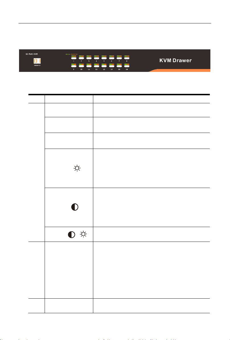
No.
Components
Function
1
1-16
Switching freely from port 1 to port 16
Reset
Press 【1】and 【2】 at the same time for three
seconds resets the keyboard and mouse
Scan
Press【7】 and【8】at the same time for three seconds
enters the auto scan mode.
Brightness
Press 【 3 】 for three seconds enters brightness
adjusting mode.
33 are flashing on the LED tube.
Then press 【5】,【6】to adjust.
Press【3】exits or waits for five seconds and it will
auto-exit.
Definition
Press 【 4 】 for three seconds enters definition
adjusting mode.
44 are flashing on the LED tube.
Then press 【5】,【6】to adjust.
Press 【4】 exits or waits for five seconds and it will
auto-exit
Initialize
Press 【 6 】 for three seconds will initialize the
brightness and definition of each port.
2
Port Selection
Buttons & LEDs
Indicator LEDs are built into the switches, the online
LED light is on the left and the selected LED light is on
the right.
1. An online LED light (green) indicates that the
KVM has connected to its corresponding
computer and power on.
2. A selected LED light (orange) indicates that the
computer attached to its corresponding port is
up and running.
3
Station ID
Display the current port
3. LED Operation
3.1 LED Functions
Figure 3.1 LED front views
- 10 -
8 Port /16 Port/24 Port/32 Port User Manual
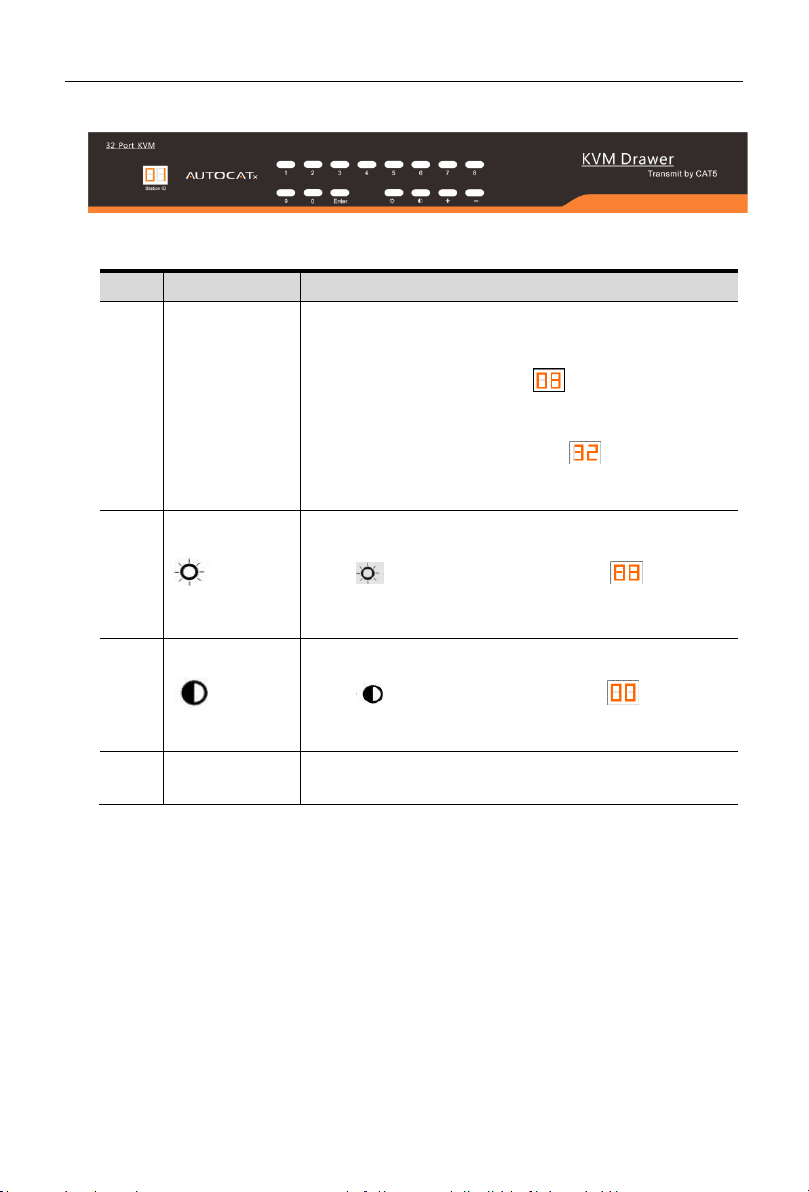
No.
Components
Function
1
0~9 +Enter
Switching from port 1 to port 32
Port 8 : If you want to switch to Port 8, press【8】,
and the LED light displays , then press “Enter”,
you will come to Port 8.
Port 32: If you want to switch to Port 32, press【3】
and【2】, the LED light displays , and then press
“Enter”, you will come to Port 32.
2
(+, -)
Adjust Brightness
Press , the LED light blinking with , and then
press “+” and “–“to adjust the brightness.
3
(+, -)
Adjust Definition
Press , the LED light blinking with , and then
press “+” and “-“to adjust the definition.
4
Station ID
Display the current port
Figure 3.2 32 Port LED front views
- 11 -

8 Port /16 Port/24 Port/32 Port User Manual
Buttons
Functions
MENU SELECT
Brings up the main menu.
EXIT/AUTO
Exits the current menu and returns to the previous menu or
exits the LED OSD.
Press AUTO for automatic configuration.
SL-/SL+
Moves the menu to make corresponding adjustment.
LED state
Green: Running
Red: Power off or access non standard VESA signal
Flashing green: Energy saving mode or no signal
3.2 Operating the Monitor
Figure 3.4 Monitor adjust menu buttons
The LED OSD allows you to set up and configure the LED display.
Press AUTO if the screen migrates after power on or under other circumstances, then the
screen auto-configures to its best display state.
Note:
It may not be adjusted to its best state if part of the display mode is not standard
VESA mode. if so, return back to OSD menu to RESET, then it will revert back to
normal.
It is recommended to set up the display mode at 1920×1080@60Hz, refresh rate
at 60Hz.
- 12 -

8 Port /16 Port/24 Port/32 Port User Manual
Pop up the
UI interface
Double click【L_Ctrl】
Double click【L_Alt】
Double click【Scroll Lock 】
Double click【Caps Lock】
Hot key
【L _Alt】 +【L_Ctrl】
【L_Win】+【L_Ctrl】
【L_Alt】 +【L_Win】
Function
Operating
Function description
Port switch
+Number
Skip ports from 1~16
+ 【↑】/【←】
Skip to previous port
+ 【↓】/【→】
Skip to next port
Brightness
+【+】
+
+【-】
-
definition
+【>】
-
+【<】
-
Reset Video
+【R】
Reset the video
Lock KVM
+ 【L】
Lock KVM and a user login window
appears
3.3 Key Combination Function
If you want to set other hotkeys to pop up the UI interface or key combination switch, set
up the via the local console, 【System Settings】> 【Device info】
Hotkey commands are as follows:
Hot key + the corresponding function key
- 13 -
8 Port /16 Port/24 Port/32 Port User Manual
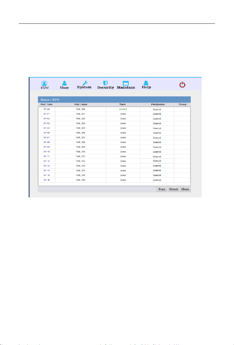
4. User Interface Operation
login UI control menu
User Name: admin
Password: admin
After logging in the device, you can see the connection status of the device port.
In the port list,
1. Click the “Connect" to enter the host screen;
2. In the host screen, press the [L_Ctrl] key on the keyboard twice.
3. Return to the UI interface.
- 14 -
 Loading...