

KinAn DL2908i, DL2924i, DL2932, DL2916i User Manual
- 1 -
Rack Dual Rail CAT5 KVM over
IP Console
(8 Ports /16 Ports /24 Ports /32 Ports)
User Manual
www.szkinan.com
@all right reserved Shenzhen KinAn Technology Co., Ltd
Printing date:2015/01
Version: V2.0

8 Port /16 Port /24 Port/32 Port User Manual
- 2 -
Contents
1.Product Overview ................................................................................ 4
1.1Brief Intruction ................................................................................. 4
1.2Features ........................................................................................... 4
1.3Appearance ..................................................................................... 5
Front View ......................................................................................... 5
Rear View .......................................................................................... 6
Structure and Size ............................................................................. 7
2.Installation and Start-up ..................................................................... 7
2.1 System Requirements .................................................................... 7
2.2 When the Server is Up and Running .............................................. 8
2.3 When the Server is Dead ............................................................... 8
2.4 Rack Mounting ................................................................................ 9
2.5 Install KVM Components .............................................................. 10
2.6 Cascade Installation ..................................................................... 11
2.7 Opening the Console .................................................................... 13
2.8 Closing the Console ..................................................................... 13
3.LED Operation ................................................................................... 16
3.1 LED Functions .............................................................................. 16
3.2 Operating the Monitor ................................................................... 16
4. OSD Operation .................................................................................. 17
4.1 OSD Overview .............................................................................. 17
4.2 OSD Functions ............................................................................. 18
F1 .................................................................................................... 19
F2 .................................................................................................... 22
F3 .................................................................................................... 23
F4 .................................................................................................... 24
F6 .................................................................................................. 25
F7 .................................................................................................... 25
F8 .................................................................................................... 25
4.3 Cascade Function ......................................................................... 26
5.IP Settings .......................................................................................... 27
5.1 Initial IP configuraiton over Network ............................................. 27
5.2 Configuration set up via serial console ........................................ 27
6.Logging In .......................................................................................... 29
6.1 Remote Control ............................................................................ 30

8 Port /16 Port /24 Port/32 Port User Manual
- 3 -
7. IP Menu .............................................................................................. 38
7.1 Remote Console ........................................................................... 38
KVM Console .................................................................................. 38
Telnet Console ................................................................................ 39
Remote Wake-up ............................................................................ 40
7.2 Virtual Media ................................................................................. 43
FDD Image ...................................................................................... 44
CD/ DVD Image .............................................................................. 47
Drive Redirection ............................................................................ 55
Virtual Drive ..................................................................................... 60
7.3 User Management ........................................................................ 60
Changing Password ........................................................................ 61
Users and Groups ........................................................................... 62
7.4 KVM Settings ................................................................................ 64
User Console .................................................................................. 64
Keyboard/Mouse ............................................................................. 68
Video ............................................................................................... 69
7.5 Device Setings .............................................................................. 71
Network ........................................................................................... 71
Dynamic DNS .................................................................................. 72
Security ........................................................................................... 75
Certificate ........................................................................................ 76
Serial Port ....................................................................................... 80
Date/Time ........................................................................................ 81
Event Log ........................................................................................ 82
7.6 System Maintenance .................................................................... 85
Device Information .......................................................................... 85
Event Log ........................................................................................ 87
Upgrade Firmware .......................................................................... 88
Unit Reset ....................................................................................... 92
Appendix ............................................................................................... 93
USB Emulation Keyboard ................................................................... 93
Mac Keyboard ................................................................................. 93
Sun Keyboard ................................................................................. 94
Specifications ...................................................................................... 95

8 Port /16 Port /24 Port/32 Port User Manual
- 4 -
1. Product Overview
1.1 Brief Introduction
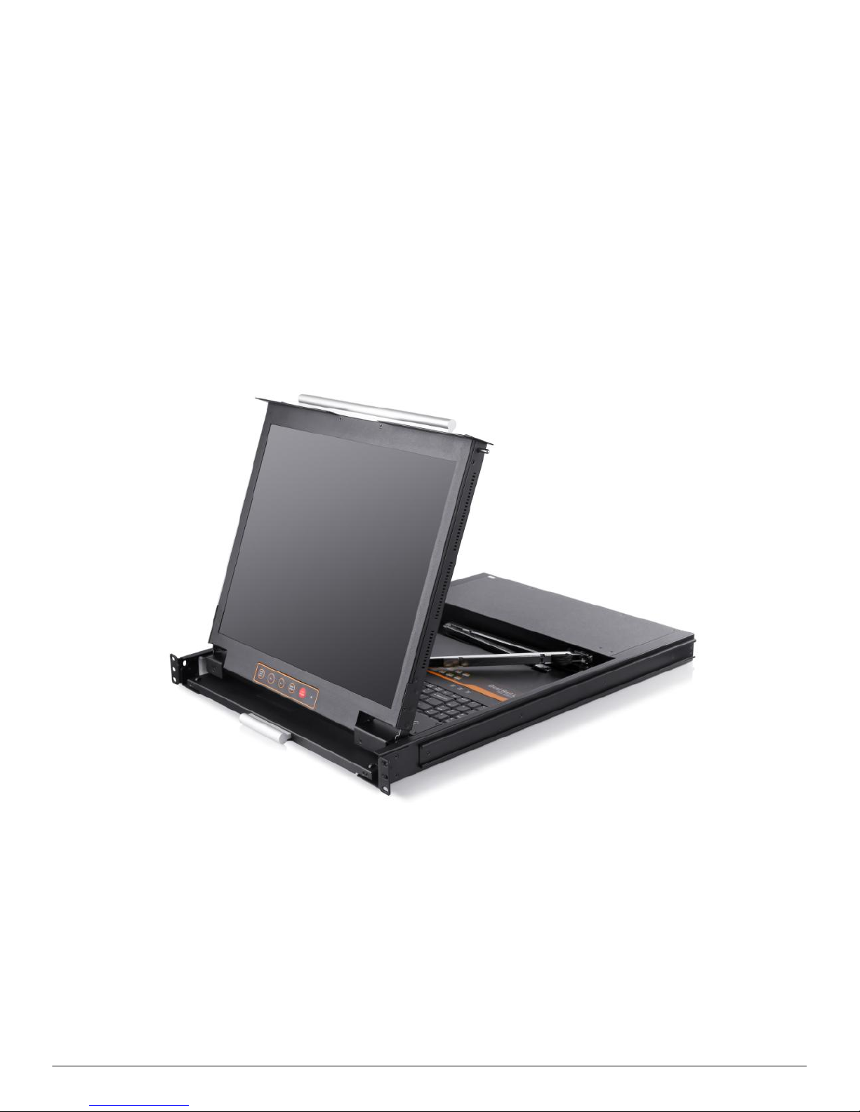
The LED panel and keyboard/touchpad modules slide independently of each
other, the keyboard/touchpad module slides back to “hide away” when not in use,
while the thin profile LED monitor rotates backflush against the rack allowing
administrators to easily monitor computer.
To make it more convenient, external USB or PS/2 keyboard/mouse/monitor are
added to rear panel.
KVM - over - IP(Hereinafter refers to IP-KVM) reloads the local keyboard,mouse
and video to a remote management console.Operator can safely get the BIOS level
access,maintenance,support and recover system fault by using the standard Internet
browser. It has passed SLL security certification and has been encrypted.
IP-KVM can easily access and control the remote KVM via LAN or Internet.It
gathers the compressed video signal and the keyboard/mouse signal, then converts
them into digital signal and transmits to the remote computer. IP-KVM supports
remote access and provides solutions for control non-invasion remote.
IP-KVM console integrates multiple ports KVM switches in a 1U height console.
It can control multiple computers with a set of device including monitor, keyboard and
mouse. Thus save much cost and space to separately equip keyboard, mouse and
monitor for every computer.
It is easy and fast to install the KVM console; you just need to connect
corresponding cables to the right ports of KVM and its module without software
configuration. Connect multiple computers with RJ-45 connector and CAT5 cable,
transmitting distance is up to 150M without a KVM extender.
1.2 Features
19” LED TFT LED monitor, high brightness, high resolution
Standard 19” metal rack integrated in 1U height
Ultra slim 99 keys PS/2 keyboard with small numeric keyboard
High resolution and high flexibility with touchpad; with two function buttons
and scroll wheel,standard PS/2 port
Access and control up to 8,16 or 32 computers, supports KVM seamless
mixed cascade connection
Extending the transmitting distance between the console and the
computer--1600*1200@60Hz(50m),1280*1024@60Hz(100m),
1024*768@60Hz(150m)
Support multiple platforms: Windows2000/XP/Vista,Linux,Mac and Sun
No software--Easily port selection via OSD menu
Hot pluggable --add or remove computers without having to power down the
switch
Auto scan feature for monitoring user-selected computers
8 Port /16 Port /24 Port/32 Port User Manual
- 5 -
Broadcast mode--operations simultaneously performed on all selected
computers
PS/2 keyboard and mouse emulation
Manage server all around the world
Remote access to the KVM(Keyboard,video and mouse) through modem
Support virtual media and hardware redirection
Support any operating system even in BIOS level,during start up or in blue
screen
Support remote control via Java network browser
SSL certificate management
Automatically senses video resolution for best possible screen capture
High-performance mouse tracking and synchronization
1.3 Appearance
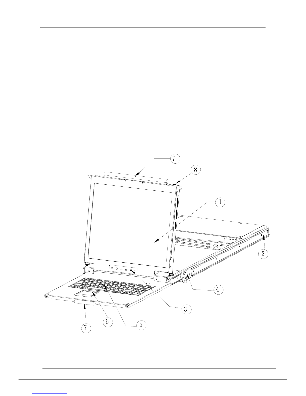
Front View
1. LED monitor
2. Rear bracket slot
3. LCD OSD controls
4. Front bracket
5. Keyboard
6. Touchpad
7. Handle
8. Release Catch
8 Port /16 Port /24 Port/32 Port User Manual
- 6 -
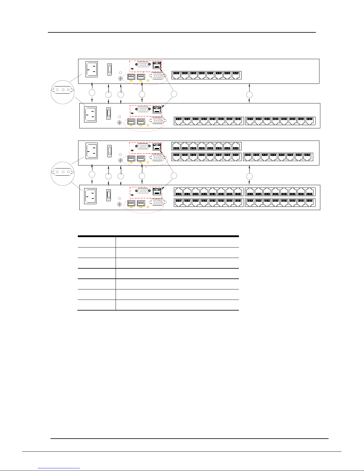
Rear View
CONSOLE
5
4
RS232
LAN
CONSOLE
RS232
LAN
100V~240V AC/47~63Hz
2
3
1
6
RTN
-48V
-36V~-72V DC IN
100V~240V AC/47~63Hz
1615141312111091 2 3 4 5 6 7 8
1 2 3 4 5 6 7 8
CONSOLE
5
4
RS232
LAN
CONSOLE
RS232
LAN
100V~240V AC/47~63Hz
2
3
1
6
RTN
-48V
-36V~-72V DC IN
100V~240V AC/47~63Hz
1615141312111091 2 3 4 5 6 7 8
1615141312111091 2 3 4 5 6 7 8
1-1 rear view
No.
Explanation
1
Ground connecting screw
2
Power input (AC or DC)
3
Power Switch
4
Local Console
5
PC connecting port
6
IP port
8 Port /16 Port /24 Port/32 Port User Manual
- 7 -
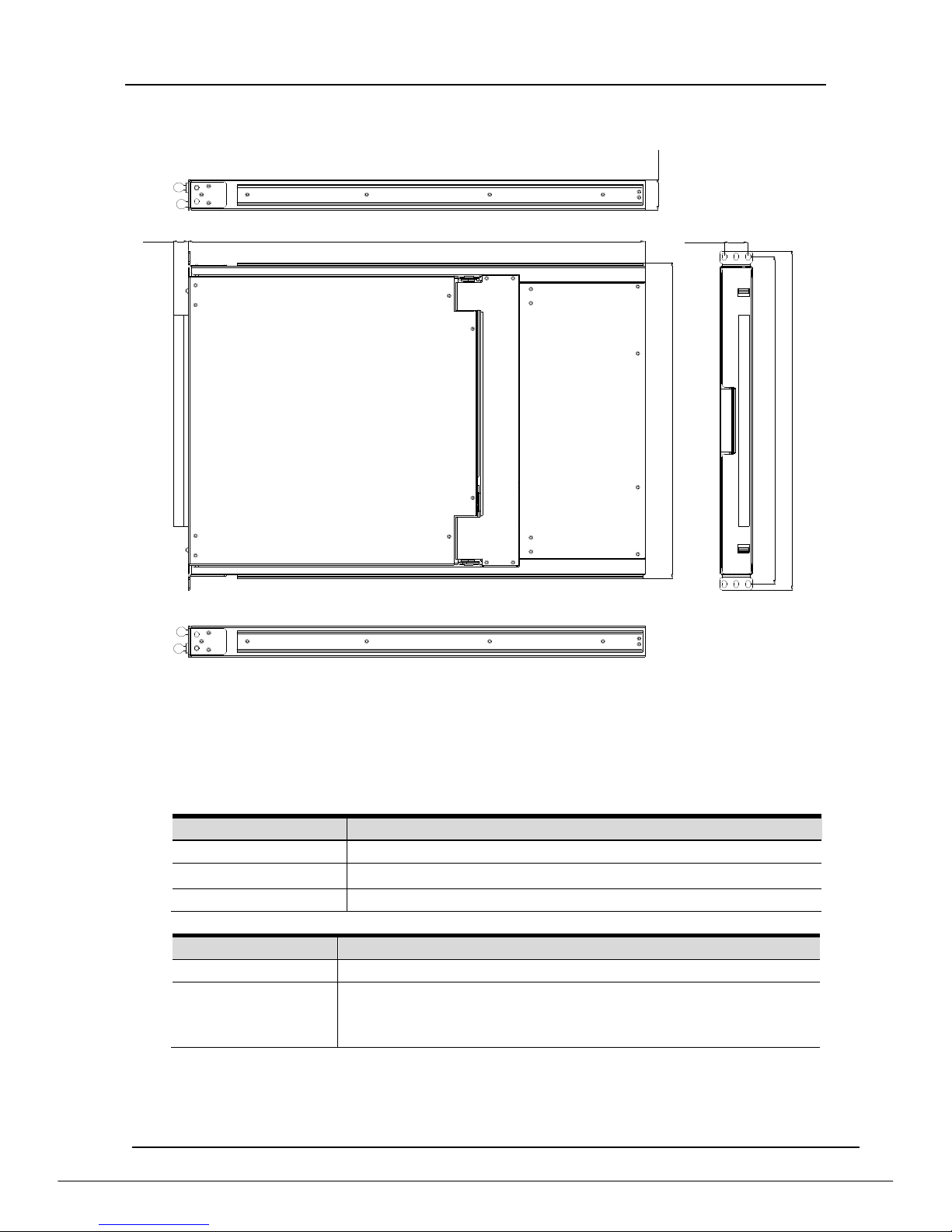
Structure and Size
605
448.4
31.76
465
481.4
19.6
43.5
Diagram 1-3: console size
2. Installation and Start-up
2.1 system requirement
Hardware
Item
Description
Local Host
8 ,16,24,32 PC/server
Local Console
One USB keyboard,one USB mouse and one monitor
Remote Console
1 PC or multiple computers connected to the network
Software
Item
Description
Local Host
No required extra software
Remote Console
(1)Java operating environment:version1.4.2 or higher
(2)Browser:Microsoft Internet Explorer (version6.0 and
above or Netscape or Mozilla or Safari)

8 Port /16 Port /24 Port/32 Port User Manual
- 8 -
2.2 When the server is up and running
The KVM-over-IP gives you a full control over the remote server. The
Management Console allows you to access the remote server’s graphics, keyboard
and mouse and to send special commands to the server. You can also perform
periodic maintenance of the server. Using the Console Redirection Service, you are
able to do the following:
1.Restart the system.
2. Watch the boot process.
3. Boot the system from a separate partition to load the diagnostic
environment.
4. Run special diagnostic program.
2.3 When the server is dead
Obviously, fixing hardware defects is not possible through a remote management
device.
Nevertheless KVM-over-IP gives the administrator valuable information about the
type of a hardware failure. Serious hardware failures can be categorized into five
different categories with different chances to happen:
1. Hard disk failure 50%
2.Power cable detached, power supply failure 28%
3.CPU, controller, main board failure 10%
4.CPU fan failure 8%
5.RAM failure 4%
Using KVM-over-IP, administrators can determine which kind of serious
hardware failure has occurred
Type of Failure
Detected by
Hard disk failure
Console screen, CMOS set-up information
Power cable detached,
power supply failure
Server remains in power off state after
power on command has been given.
CPU Controller, main board
failure.
Power supply is on, but there is no video
output.
CPU fan failure
By server specific management software
RAM failure
Boot-Sequence on boot console
8 Port /16 Port /24 Port/32 Port User Manual
- 9 -
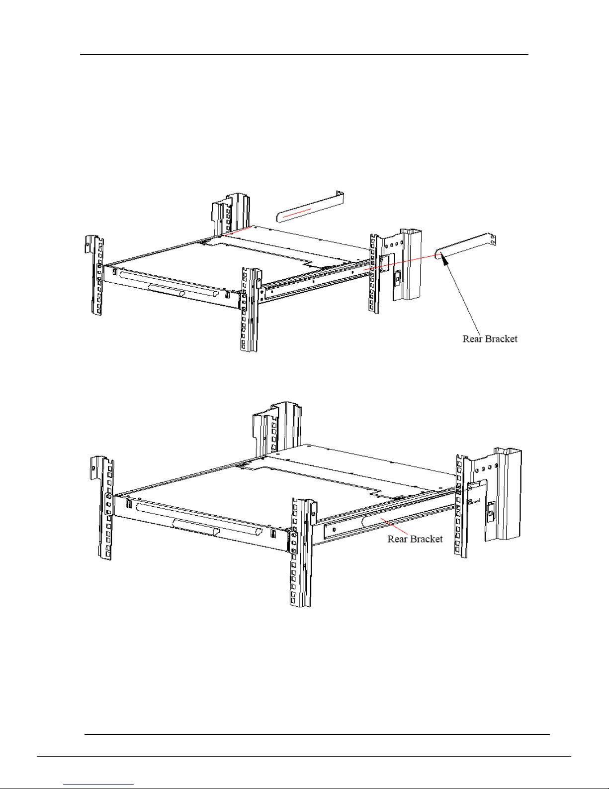
2.4 Rack Mounting
A standard rack mounting kit is provided to mount the switch in a depth of
650-850mm (17”), 670-800mm (19”) in a standard 19”rack.
With one person hold the switch in place and the other person slides the L bracket
into the switch’s side mounting brackets from the front to the back, then screws the
brackets to the rack. (See below installation drawing)
Diagram 2-1
Diagram 2-2
8 Port /16 Port /24 Port/32 Port User Manual
- 10 -
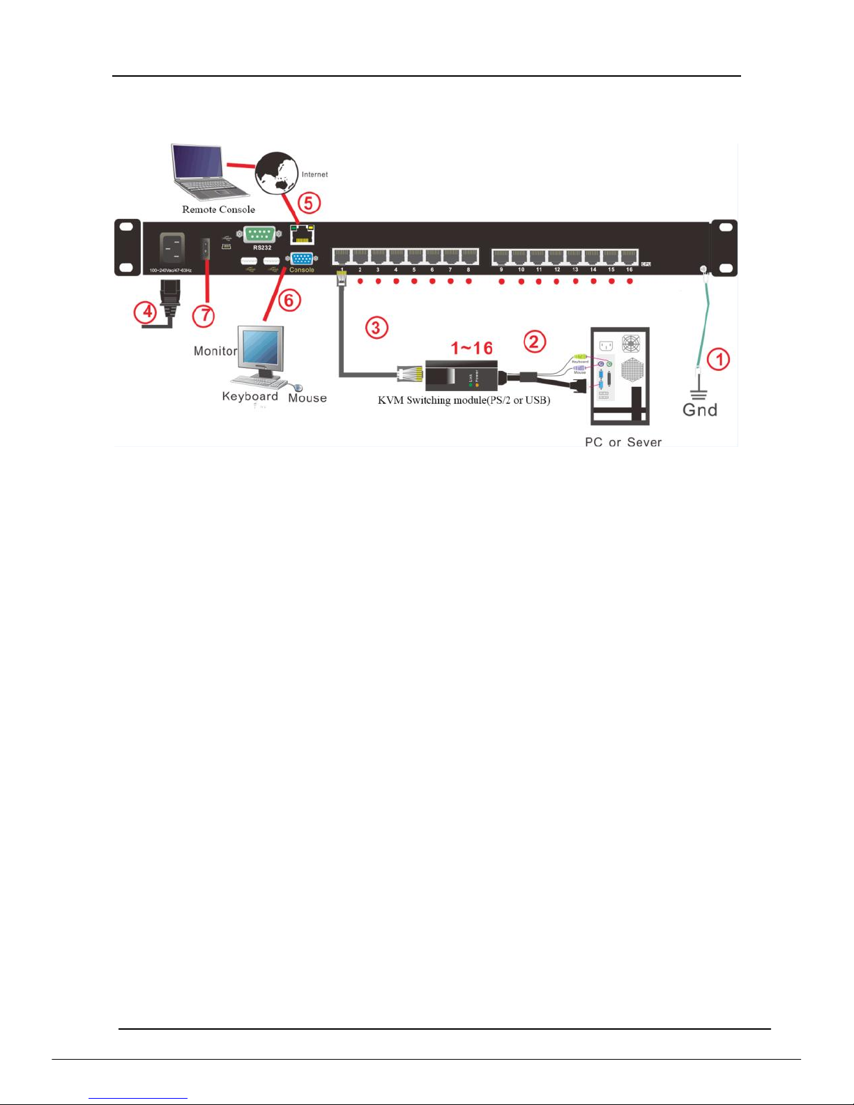
2.5 Install KVM Components
Diagram 2.3 Installation diagram
Installation Steps:
1) Make sure the KVM console has been connected to the ground.
2) Connect the KVM adapter to the host.
3) Connect the KVM adapter to the KVM port with CAT5 cable.
4) Connect the female port of the power cable to the KVM power socket, then
the male port to 220V AC power socket.
5) You can remote control the KVM switch via IP.
6) Can connect external keyboard,mouse and monitor(optional)
7) Power on the switch and you can start to use it.
8 Port /16 Port /24 Port/32 Port User Manual
- 11 -
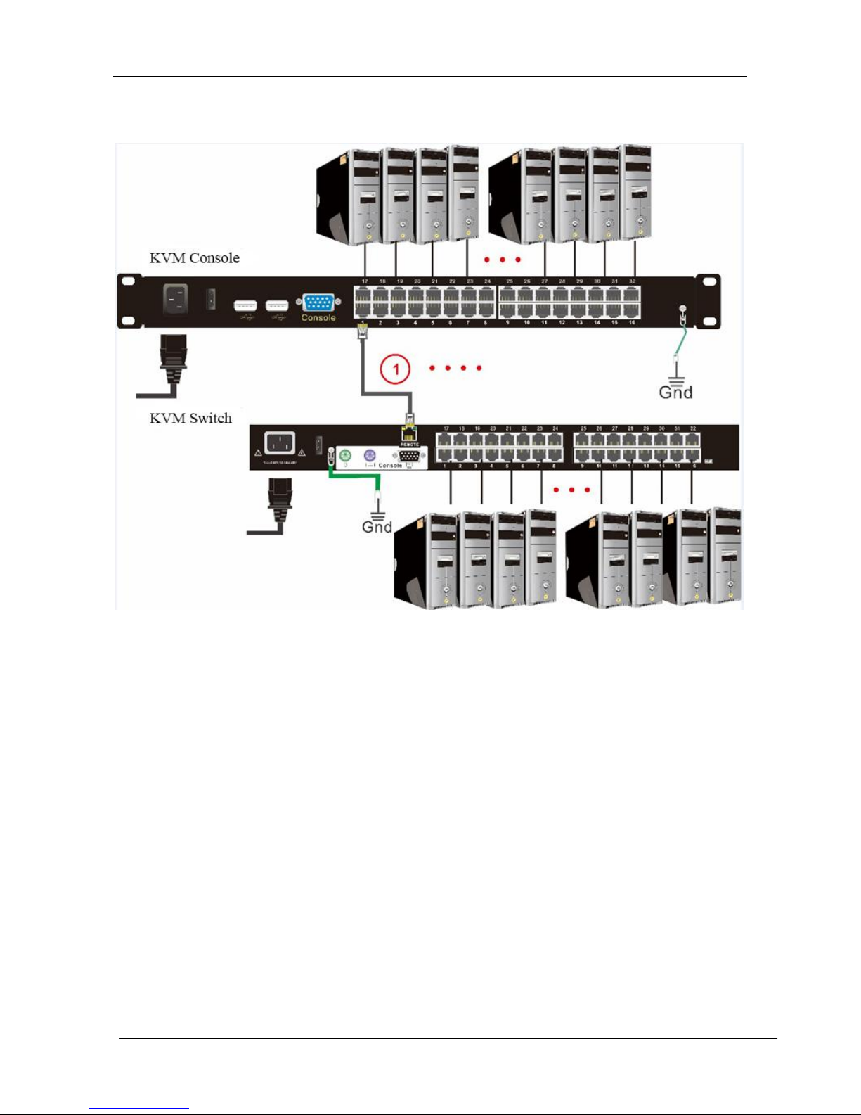
2.6 Cascade Installation
Diagram 2.4 cascade installation
Explanation:
1. Connect one port of the CAT5 cable to any RJ45 port of the console, and
connect the other port to the RJ45 port with “Chain in”of the KVM switch.
2. Repeat above operation to cascade more KVM switches.
8 Port: max cascade 8 levels
16 Port: max cascade 16 levels
24 Port: max cascade 24 levels
32 Port: max cascade 32 levels
3. Connect host computers according to 2-4.
8 Port /16 Port /24 Port/32 Port User Manual
- 12 -
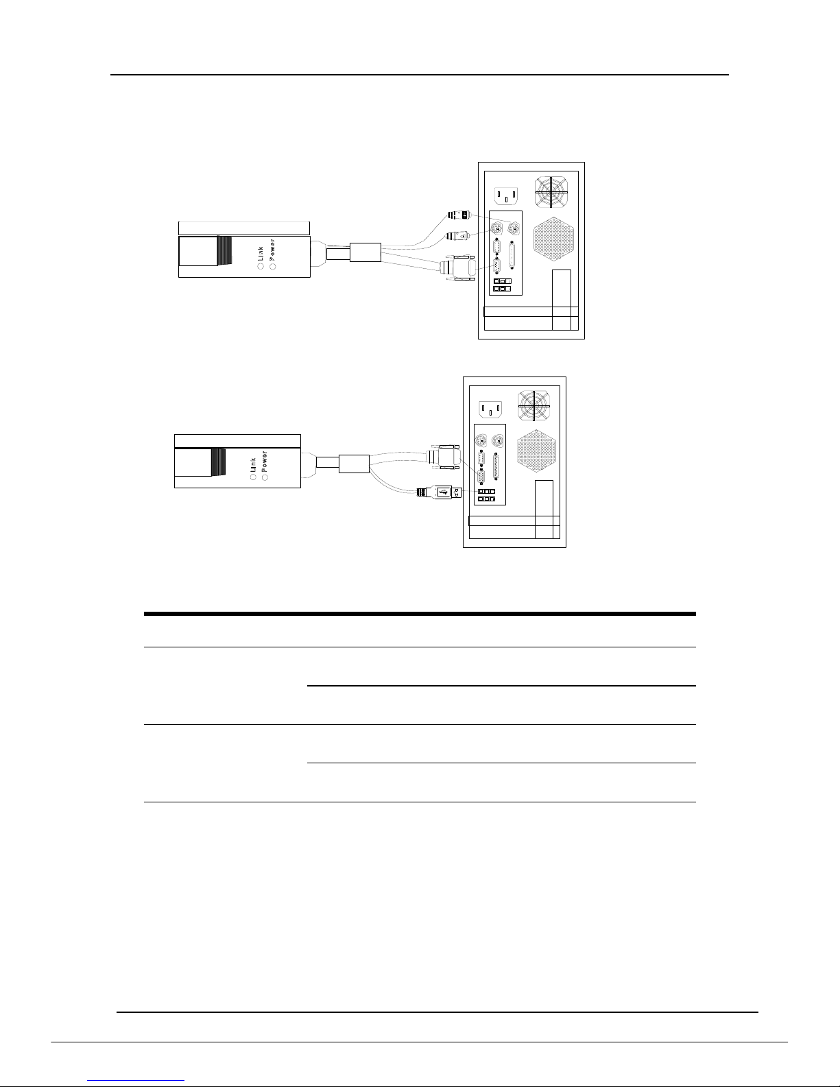
Module Explanation
PS/2 CPU module
USB CPU module
Table 1.1:Module LED indication
Components
Function
Power LED
Green light
flashing
The module has been powered on
Green light
keeps on
The module has been connected
to the KVM switch
Link LED
Flashing
quickly
The module is communicating with
the host
Orange light
keeps on
The module has been selected by
the KVM switch
8 Port /16 Port /24 Port/32 Port User Manual
- 13 -
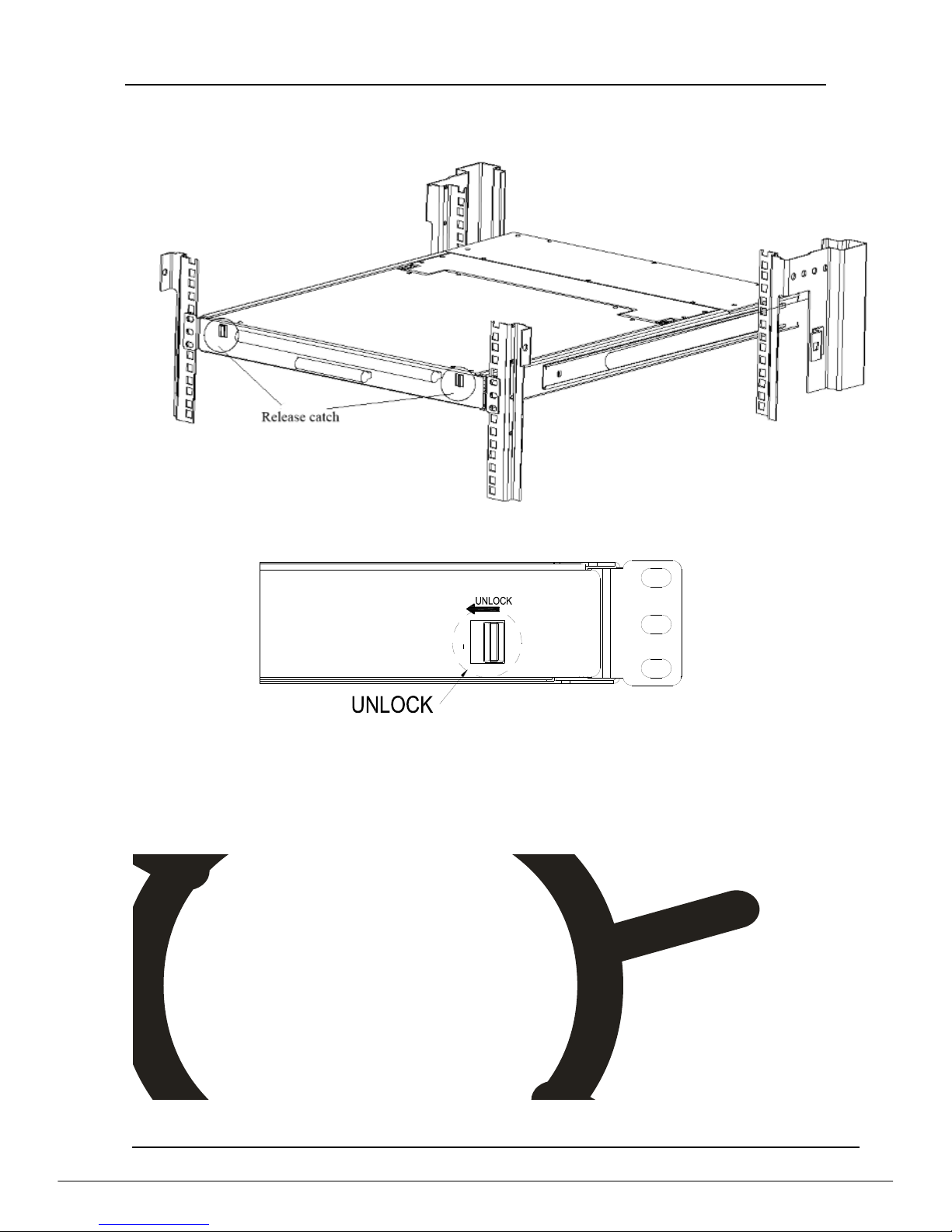
2.7 Opening the Console
Release the release catch.
2-1.3 unlocking
Pull the LED panel all the way out until it clicks into place.
Rotate the LED module all the way back to expose the LED screen; the LED

8 Port /16 Port /24 Port/32 Port User Manual
- 14 -
module can be rotated up to108°.
Pull the keyboard module all the way out until it clicks into place.
Note: The keyboard module can’t bear extra load or any surface pressure.

8 Port /16 Port /24 Port/32 Port User Manual
- 15 -
The KVM makes two “beep” sounds after power on; an OSD window appears
for you to input user name and password.
8 Port /16 Port: The orange LED and LED tube are flashing before you enter
your password.
24 Port /32 Port: appears on LED tube without user name and
password.
2-1.5 password window
LED panel is powered on when the power LED is green.
Power on the computer or server after power on the KVM.
8 Port /16 Port: The LED of the connected port is green.
24 Port /32 Port: There is no port LED.
The factory default pass word is blank; double click “Enter “to log in.
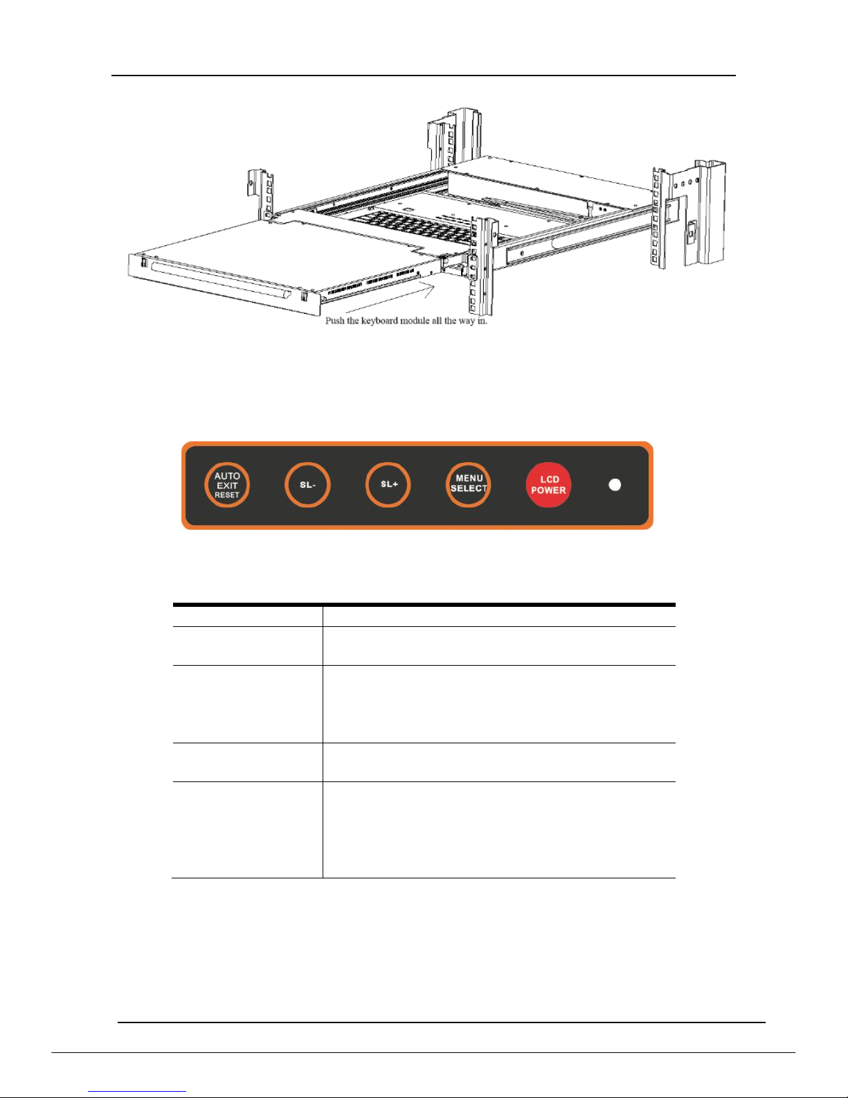
2.8 Closing the console
Pull the release catches at the bottom of the keyboard to release the keyboard
module.
Push the keyboard module all the way in.
Rotate the LED module all the way down, and then pull the rear catches to
release the module.
Push the module all the way in, it automatically locks and shut down LED
power.
8 Port /16 Port /24 Port/32 Port User Manual
- 16 -
3. LED OSD Configuration
The LED OSD allows you to set up and configure the LED display.
Buttons
Functions
MENU SELECT
Press this button invokes the menu function
and brings up the main menu.
EXIT/AUTO
Press this button exits the current menu and
return to the previous menu or press this
button exits the LED OSD.
Press AUTO for automatic configuration.
SL-/SL+
Press this button moves your menu to make
corresponding adjustment.
LED state
Green :running
Red :power off or access non standard VESA
signal
Flash green: energy saving mode or no
signal
Press AUTO if the screen migrates when power on or under other circumstances,
then the screen auto configure to its best display state.(It might can’t be adjusted to
its best state if part of the display mode is not standard VESA mode, if so return back
to OSD menu to RESET, then it will back to normal.
We suggest our customers to set up the display mode at 1280x1024, refresh
rate at 60Hz
8 Port /16 Port /24 Port/32 Port User Manual
- 17 -
4. OSD Operation
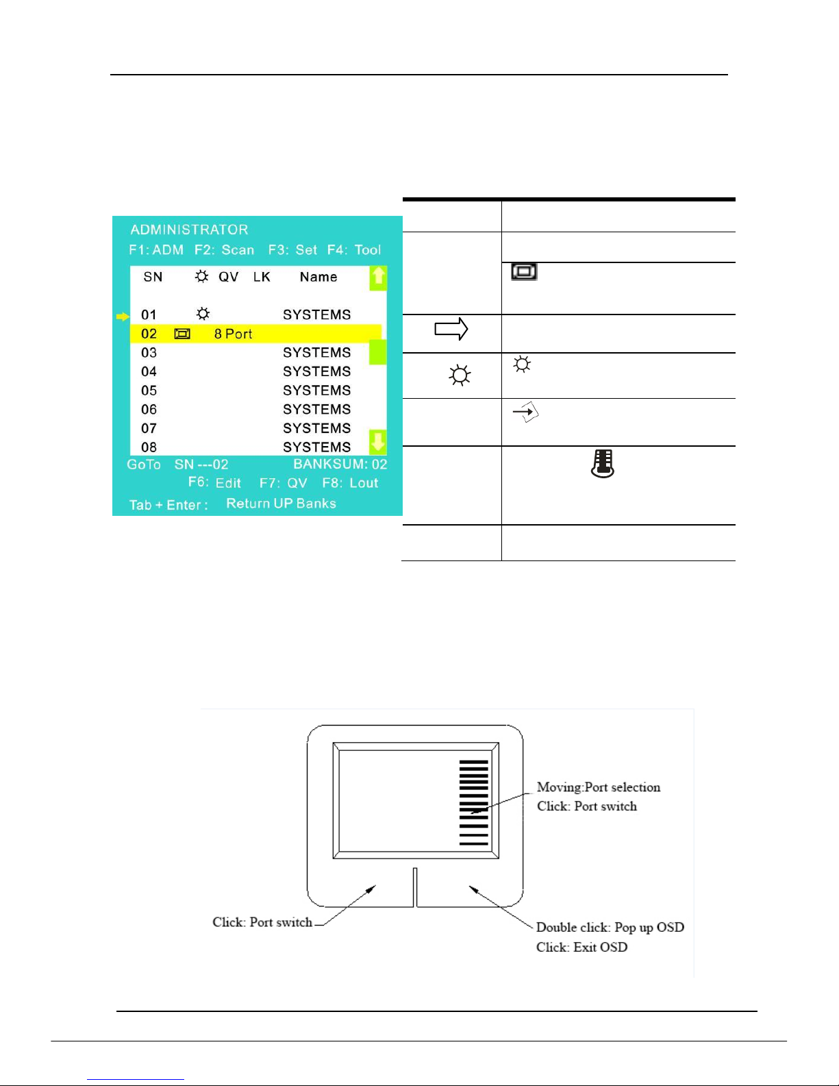
4.1 OSD Overview
Double click the right button of the mouse or double click hotkey【Scroll Lock】 to
invoke below OSD main menu. You can customize the OSD hotkeys; find more
details in OSD function instructions.
To access the OSD menu through keyboard:
1.In the submenus that appears, moving the highlight bar to your selected
port and then press Enter.
2.Press【Page Up】or【Page Down】quickly moves to next BANK
3. Press any key from 【0-9】to enter any port of current station,type
BANK+PORT to enter other stations.
To access the OSD menu through mouse:
*Note: Operate via keyboard after invoke the OSD menu via the touchpad.
Headings
Explanation
SN
Port No. of the host computer
means this post has
been cascaded a KVM
It shows the computer port
under monitoring.
Shows the corresponding
host computer is power on.
QV
means the corresponding
port is quick view port
LK
Lock sign: Shows that the
port only available for
viewing.
Name
Port name, max 12 bytes

8 Port /16 Port /24 Port/32 Port User Manual
- 18 -
4.2 OSD Functions
Menu
Keys
Submenu/Explanation
ADM
F1
Set User login-Set User login account and password
Set accessible-Set access permissions
BRC Mode -monitor multiple computers at the same
time
Load Default-reset the menu to the original factory
default settings
Scan
F2
All-Lists all the ports on the installation
Power On-lists only powered on ports that have
attached computers.
Quick View-Lists only the ports that have been
selected as Quick View ports
Set
F3
Auto Scan-set scanning time period
Port ID-set how long a port displays on the monitor
OSD Hotkey-set OSD hotkeys
Lout Time off- to set the time out value
Tool
F4
Reset RGB-Press Enter reset RGB
Beeper【On】-press Enter switch Bee sounds
Mouse Hot 【 On】 -press Enter to close touchpad
operating on OSD.
Restore Values-press Enter restore the current user
default value.
About KVM- press Enter shows the KVM version
Edit
F6
Edits port names
QV
F7
Start or close Quick View
Lout
F8
Log out/lock the KVM
Exit
Esc
Press this key exits OSD menu
Scroll Lock
Press this key exits OSD menu
Num Lock
Press this key exits OSD menu
Table 1.5
The display screen will be distorted if the CAT5 cable is too long, for this case, you
can adjust according to below steps:
1. Press【+】 and ADJ FOCUS will pop up, then press【+】,【-】to adjust definition.
2. Press【,】and ADJ BRIGHT will pop up, then press【,】【.】to adjust brightness.
8 Port /16 Port /24 Port/32 Port User Manual
- 19 -
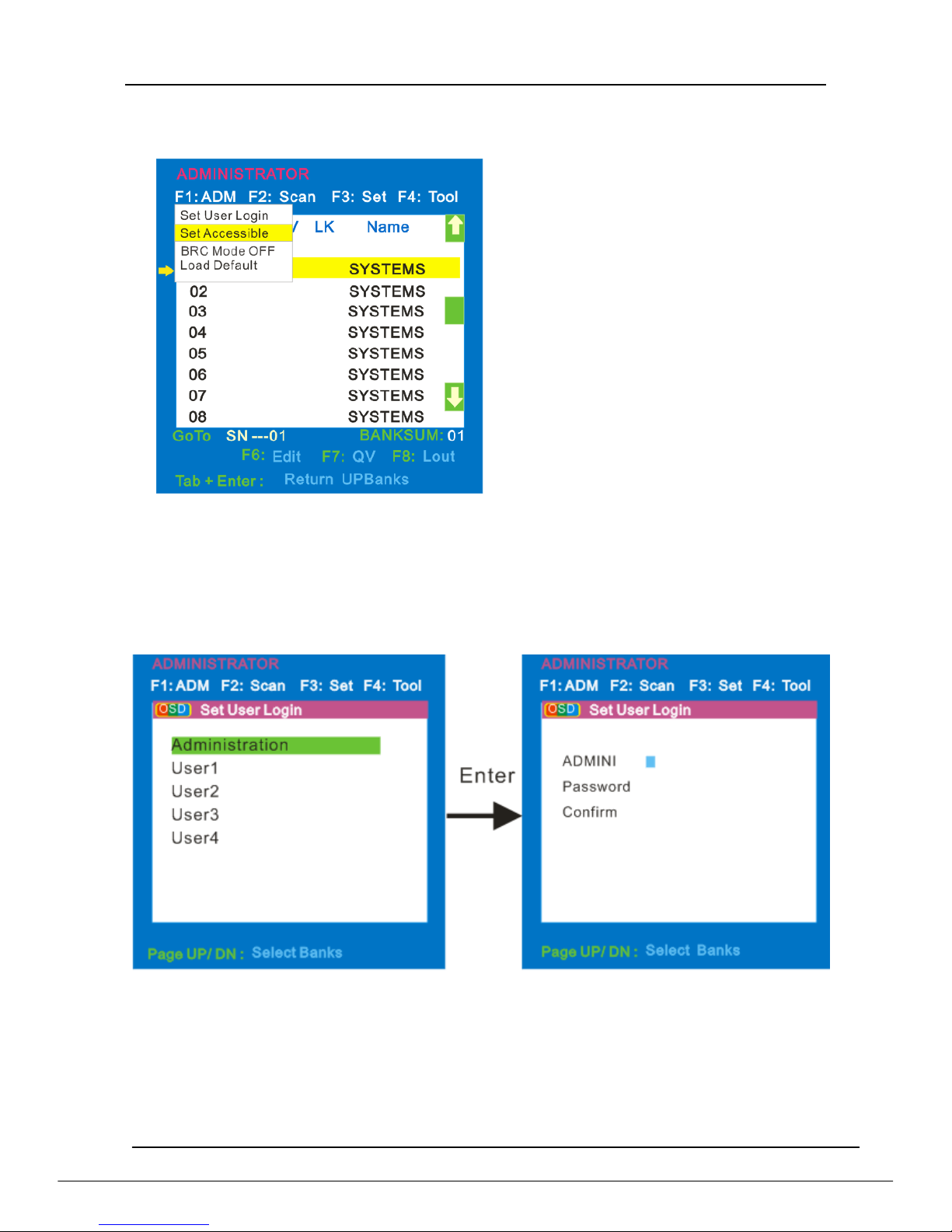
F1
Menu Overview
Menu Explanation
1. Set User Login—Press [Enter] selects Set User Login and a screen as below
diagram 4-1.1 appears:
One administrator and four users account can be set (the account and the
password are no more than 16 characters)
Diagram 4-1.1 Diagram 4-1.2
Note:You can set up an account and password according to diagram 4-1.2, then
“ User setup ok” pops up showing that you have done your set,“ and if
“Password Not Match”pops up,you need to type in your password again
as you did in your first type.
Operating instructions
1) Press【F1】or 【←】【 →】enters the
F1 submenus.
2) Press 【↑】【 ↓】moves the highlight
bar to select the submenu.
3) Press 【Enter】 selects and exits
ADM menu.
4) Press【Esc】cancels the operation
and exits ADM menu.
8 Port /16 Port /24 Port/32 Port User Manual
- 20 -
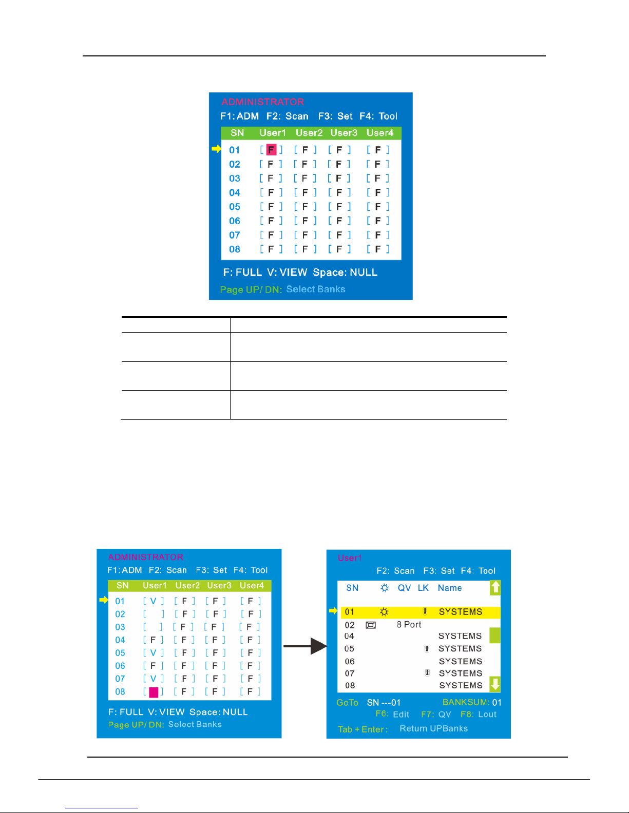
2. Set Accessible—press [Enter] to select Set Accessible, then below menu appears:
(diagram 4-1.3)
Diagram 4-1.3
Menu
Explanation
FULL
Full access function to the station and can do any
operation to the ports
VIEW
Read only function, you can only read the port but
you can’t operate it if set this function.
NULL
If you set this function, the port will be not
displayed on the user’s OSD menu
Note:The administrator always has full access to all the ports.
E.g. 1) If you want to set access permission of [User1], press【Space】to
select the permission options you need to set.
2) If you want to set access permission of cascade port, press【Page
Down】 moves to next level, and the SN changes into Bank –
Port( eg.: 02-01), then press【 Space】to select the permission
options you need to set.
3) [User1] log in OSD menu, as shown in below diagram 4-1.5.
Diagram 4-1.4 Diagram 4-1.5
8 Port /16 Port /24 Port/32 Port User Manual
- 21 -
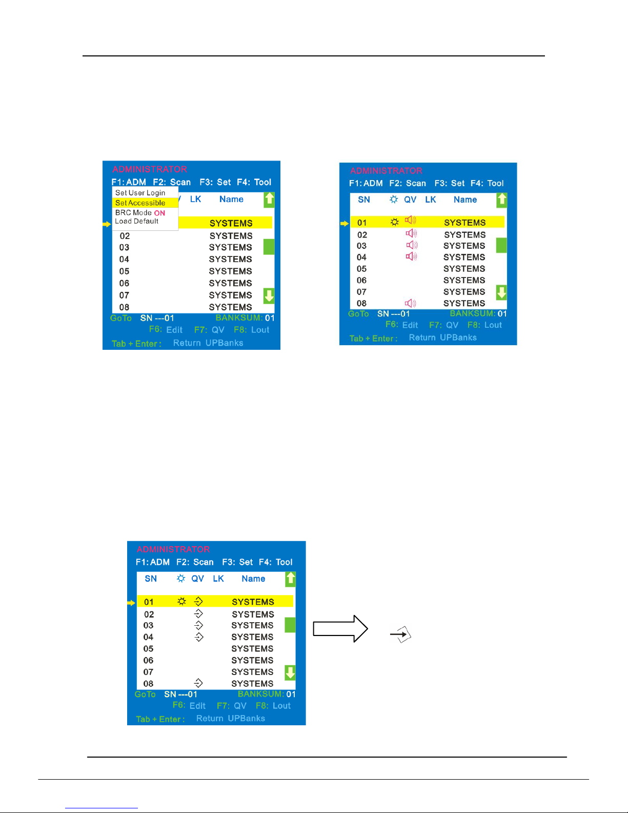
3. BRC Mode Off - Press [Enter] to enter the BRC mode, enter the main menu,
press F7 to add or delete a port that need broadcast function. When BRC mode is
effect, a speaker symbol appears in QV column. (See below diagrams).
While BRC mode is in effect, we can synchronous operate multiple computer
ports.
Note: While BRC mode is in effect, the mouse is forbidden to use.
Diagram 4-1.6 Diagram 4-1.7
1) Open BRC mode
F1->BRC Mode OFF-> [Enter] -->BRC Mode ON (diagram 4-1.6)
2) Open the port that need broadcast function
Press【↑】【 ↓】key—>select the port that need broadcast function F7a speaker
symbol appears in the QV column which shows the port has entered broadcast
mode.
3) Close the broadcasting port
press【↑】【 ↓】key—>select the port F7exit BRC mode and the speaker symbol
disappears
4) Exit BRC mode
Invoke OSD main menu F1->BRC Mode ON -> [Enter] --> BRC Mode OFF, KVM
exit BRC mode (diagram 4-1.8)
Diagram 4-1.8
F1->BRC Mode OFF
->[Enter] ,enter the main menu,
all symbols turn into
speaker symbol(diagram
8 Port /16 Port /24 Port/32 Port User Manual
- 22 -
4. Load Default--- press [Enter] to select the submenu, all the set values are restoring
to original factory default settings.
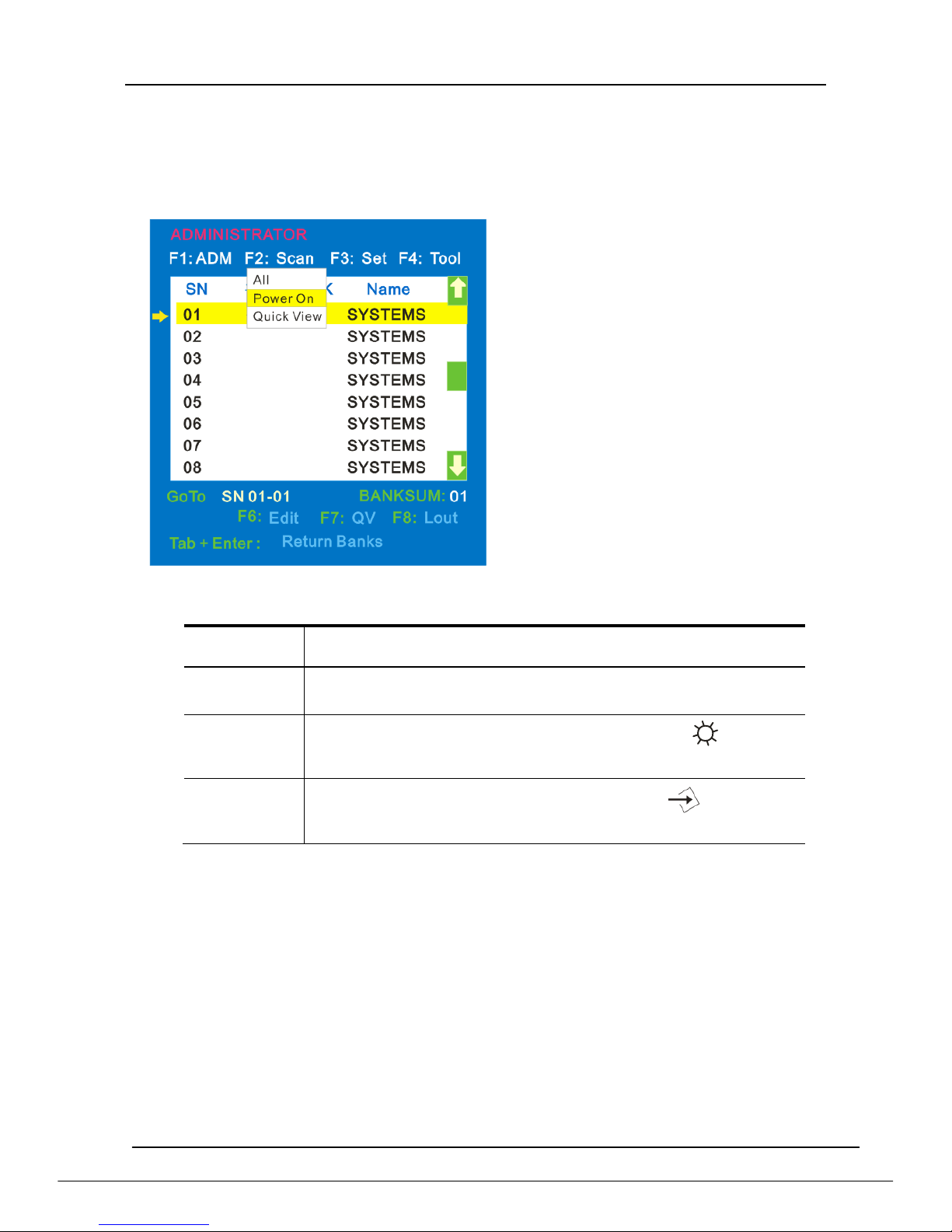
F2
Menu Overview
Menu Explanation
Submenu
Explanation
All
Use this function to scan all ports according to the set
scanning interval.
Power On
Use this function to scan all signal ports with according
to the set scanning interval.
Quick View
Use this function to scan all ports with quick view
symbols according to the set scanning interval.
Operating instruction
1) Press【F2】or 【←】【 →】enters the
F2 submenus.
2) Press 【↑】【 ↓】moves the highlight
bar to select the submenu.
3) Press【 Enter】 selects and exits
Scan menu.
4) Press【Esc】cancels the operation
and exits SCAN menu.
8 Port /16 Port /24 Port/32 Port User Manual
- 23 -
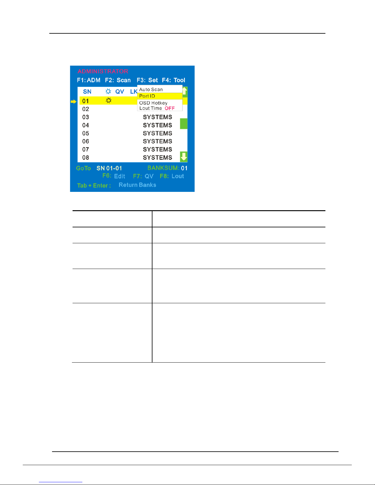
F3
Menu Overview
Menu Explanation
Submenu
Default value
Auto Scan
5S(effective range 5-99)
Port ID
0S: not display the port ID
1-98S: display the seconds, maximum 98s
99S: permanent display
OSD Hotkey
[Scroll Lock ] +[Scroll Lock ]
[CapsLock] +[CapsLock]
[F12] + [F12]
[Ctrl]+[Ctrl]+[KVM Hotkey]
Lout Time off
0: off
01-99M:set the screen saver timeout, it is
automatically log out if the current operator
is no longer operate for a while, then the
KVM will be locked and you need to enter
user name and password to operate again
Operating instructions
1) Press【F3】or 【←】【 →】enters the
F3 submenus.
2) Press 【↑】【 ↓】moves the highlight
bar to select the submenu.
3) Press【Enter】selects and exits Set
menu.
4) Press【Esc】cancels the operation
and exits Set menu.
8 Port /16 Port /24 Port/32 Port User Manual
- 24 -
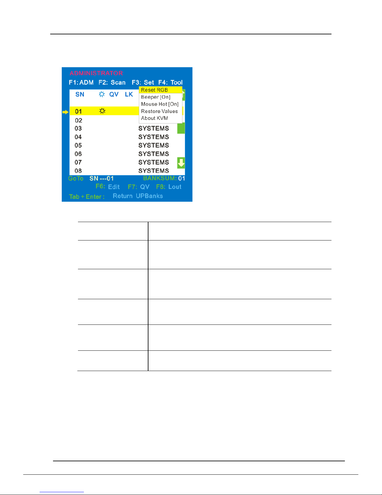
F4
Menu Overview
Menu Explanation
Submenu
Instruction
Reset RGB
Restore the video signal to the default value.
Beeper【On】
The beeper can be turned on or off with this function.
Mouse Hot【On】
To open and close the mouse with this function.
We can’t operate the OSD when it is【Off】.
Restore Values
Restore to original factory default values.
About KVM
It shows the KVM version information.
Operating instructions
1) Press【F4】or 【←】【 →】enters
the F4 submenus.
2) Press 【↑】【 ↓】moves the
highlight bar to select the
submenu.
3) Press【Enter】 selects and
exits Tool menu.
4) Press 【 Esc】 cancels the
operation and exits Tool
menu.
8 Port /16 Port /24 Port/32 Port User Manual
- 25 -
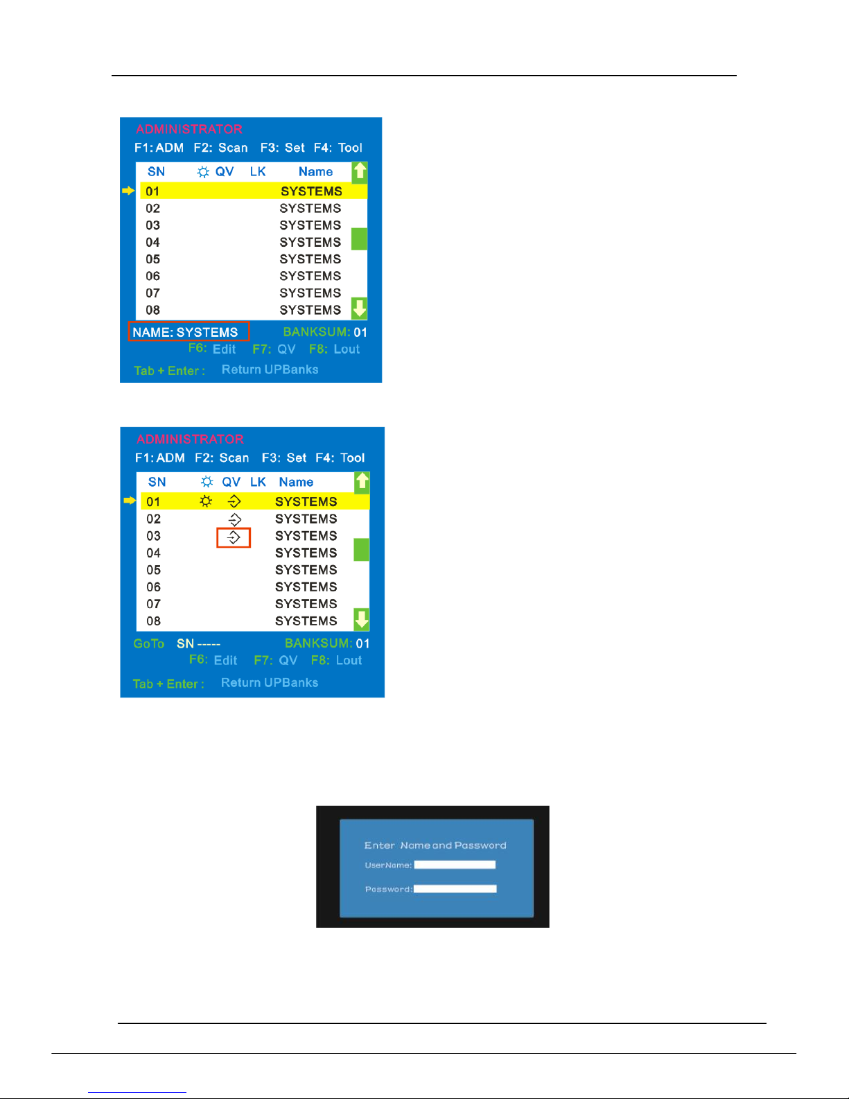
F6-Edit port names
F7-Set Quick View port
F8-LOUT
Press【F8】exits the OSD main menu and fully exits current port, then the log in
window appears:
Users must log in all over again to regain access to the OSD.
Choose the port with【↑】【 ↓】 key;
Press F6 and key in the new name or
modify the old one, then press Enter to
save the name and exit editing.
Press 【Esc】to cancel and exit the
editing.
Note:
The NAME characters include:
All alpha characters:A-Z
All numeric characters:0-9
Select ports with【↑】【 ↓】keys;
Press F7to include current port as
Quick View, then an arrowhead
appears in the QV column to
indicate so;
Note:
Press F7 to cancel the QV symbol if
the current port has already have a QV
arrowhead symbol in its QV column; if
you want to cancel all the QV function,
press Restore Values under
F4:Tool.( The port name restores to
default setting at the same time.)
8 Port /16 Port /24 Port/32 Port User Manual
- 26 -
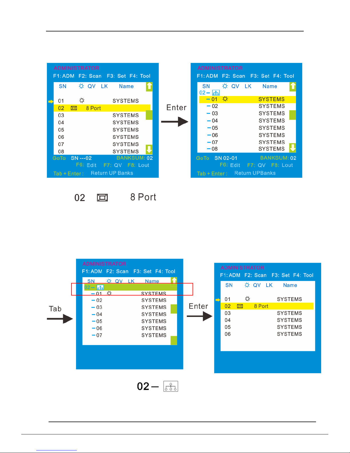
4.3 Cascade Function
1. Operate the host computer under cascade
Diagram 4-1.5 Diagram 4-1.6
Explanation:
Shows that we have already connected an 8
port KVM to port 2(see diagram 4-1.5), we can connect 8 computers to the 8 port
KVM. Press【 Pa UP】to select port on current station, then press 【Enter】to operate
the port.
2. Return to OSD main menu
Note:
1. Press【Tab】, then in column SN changes into green, which
indicates the port has been selected. Then press【Enter】to return to main
menu to operate other ports.
2. Press【Pa DN】returns to the OSD main menu.
8 Port /16 Port /24 Port/32 Port User Manual
- 27 -
5.IP Settings
5.1 Initial IP Configuration via Network
IP - KVM factory default settings:
DHCP
forbidden
Default IP address
192.168.0.70
Default Subnet mask
255.255.255.0
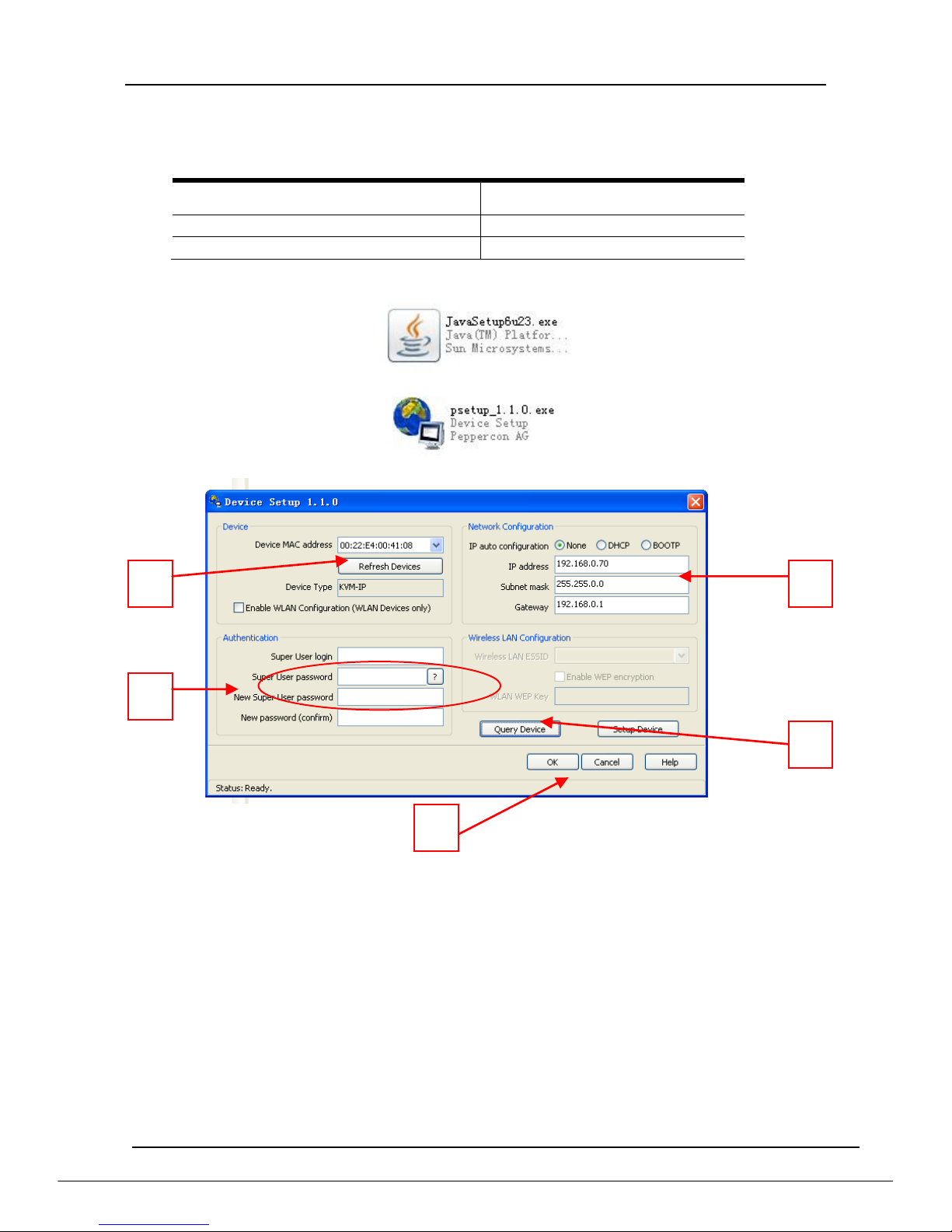
1) Read the CD and double click JAVA, ensure the Internet is available and install
the JAVA step by step according to indications.
2) Copy the PSETUP to the computer in use and double click PSETUP.
3) Below menu appears on the screen:
Operating instructions:
1) It automatically gets the MAC address, if it is failed to do so, press the
Refresh Devices according to above number 1.
2) Click Query Device (above number 2), it shows the IP KVM’s IP address as
well as gateway information (see above number 3).
3) Choose None in IP auto configuration, set up the IP address in above
number 3 according to your network area (eg.192.168.X.XXX) .Input your
account and password after setting the network path (above number 4).
User Login: super
Password: pass
Click OK to save your settings.
4) If you choose DHCP in IP auto configuration, there is no need to modify the
IP address, it will automatically get the proper IP address.
★~Please remember the setting IP address for remote control~★
1 2 3 4 5

8 Port /16 Port /24 Port/32 Port User Manual
- 28 -
5.2 Configuration Setup via Serial Console
For using serial terminal, the KVM-over-IP has a serial line interface (host side).
This connector is compliant with the RS-232 serial line standard. The serial line has
to be configured with the
parameters given in Table below.
Parameter
Value
Bits/second
115200
Data bits
8
Parity
No
Stop bits
1
Flow Control
None
When configuring with a serial terminal, e.g., Hyper Terminal, reset the
KVM-over-IP and immediately press the “ESC” key. You will see some device
information, and a “=>” prompt. Enter “config”, press “Enter” key and wait for a few
seconds for the configuration questions to appear.
As you proceed, the following questions will appear on the screen. To accept the
default values shown in square brackets below, press “Enter” key.
IP auto configuration None/DHCP / BOOTP):
IP address[192.168.0.70]:
Subnet mask[255.255.255.0]:
Gateway(0.0.0.0 for none)[0.0.0.0]:
IP auto configuration
With this option, you can specify whether the KVM-over-IP should get its network
settings from a DHCP or BOOTP server. For DHCP, enter “dhcp”, and for BOOTP
enter “bootp”. If you do not specify any of these, the IP auto-configuration is disabled
and subsequently you will be asked for the following network settings.
IP address
The IP address the KVM-over-IP. This option is only available if
IP auto-configuration is disabled.
Net mask
The net mask of the connected IP subnet. This option is only available if IP
auto-configuration is disabled.
Gateway address
The IP address of the default router for the connected IP subnet. If you do not
have a default router, enter 0.0.0.0. This option is only available if IP
auto-configuration is disabled
Warning:
User“super”is forbidden to log in via the serial port of the IP-KVM.
8 Port /16 Port /24 Port/32 Port User Manual
- 29 -
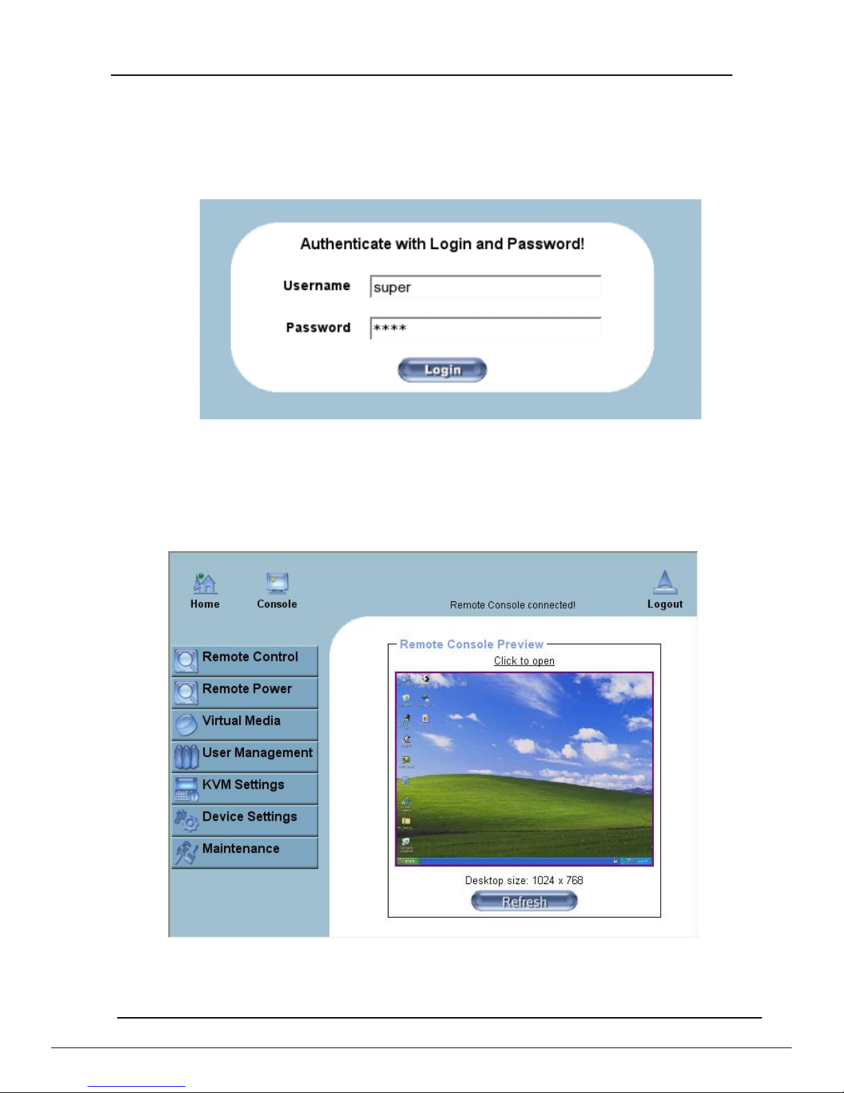
6. Log in
1) Open IE and type in the IP address you have set in PSETUP (as shown above
number 1).
http:// 192.168.0.70(the IP address you have set according to your network area)
2) A screen appears as shown in above to indicate you to type your account and
password after connected.
User name: super
Password: pass
3) Then below screen appears:
Click Console to open the IP-KVM remote console.
Warning:
If there is no activity for 30 minutes, the IP-KVM will log you out, automatically. A
click on one of the links will bring you back to the login screen.
 Loading...