

Kimray Pneumatic GEN II Installation And Maintenance Manual

CONTENTS
PAGE
Introduction 1
Scope 1
Description 1
Specication 1
Control Installation 2
INTRODUCTION
Float Operated Level Controllers
Models Pneumatic GEN II
Installation and Maintenance
IM0015
Issued 6/19
Back Mount Side Mount
CAUTION
Prior to installing, the instructions provided
herein should be completely reviewed and
understood before operating or repairing this
equipment . All CAUTION and WARNING
notes must be strictly observed to prevent
personal injury or equipment damage.
Scope
This installation manual includes instructions
and maintenance information for both
Kimray pnuematic side mount and back
mount level controllers.
Do not install, operate, or maintain a
pneumatic GEN II without being fully trained
and qualied with Kimray installation and
maintenance manual. To avoid personal
injury or property damage, it is important to
carefully read, understand, and follow all the
contents of this manual, including all safety
cautions and warnings. If you have any
questions about these instructions, contact
your Kimray applications support group
before proceeding.
Description
The GEN II side mount and back mount
level controllers are designed for use in
liquid level and liquid/liquid interface control
applications. Both provide either a throttle
modulating or snap on/off pneumatic
output and can be set to operate in a
direct increasing liquid level output signal
or indirect mode increasing liquid level
decreasing output signal.
The GEN II level controllers are equipped
with a displacer or hanger for horizontal or
vertical installation.
The side mounted is reversible for rigtht hand
or left hand installation. The
back mount is center back mounted. Both
models are standard with a 1/4” NPT tapped
vent. No gas is released into the case.
Both models include a 40 micron lter
located just downstream of the instrument
gas inlet port.
Specication
Table 1 - General Specications
Description:
Operating
Pressure:
Connection Size: 2in. - 6in.
Body Material: Steel
Connection Type:
Actuation:
Control Range: 2 - 10 in.
Temperature:
When ordered, the GEN II level controller
conguration and construction materials
were selected to meet specic pressure,
temperature, pressure drop and uid
conditions. Since some body/trim material
combinations are limited in their pressure
drop and temperature ranges, do not subject
the GEN II level controller to any other
conditions without rst contacting the Kimray
Inc, sales ofce or a sales / applications
representative.
Pneumatically Operated
Level Controller.
(0-4000) psig (276 Bar)
NPT, Flg, Grv, HU
Grooved
Snap, Throttle
Adjustable
-50° to 300° F
-45° to 149° C
CAUTION
WARNING
Do not exceed the maximum pressure
specied on the controller nameplate. Under
no circumstances should the controller
supply pressure ever exceed the maximum
psig.
Before beginning installation of the GEN II
•Read and follow instructions.
•Make sure all pressure has been removed
from the vessel before opening any connec
tions.
WARNING
If a level controller is used in a hazardous
or ammable uid service, personal injury
and property damage could occur due to
re or explosion of vented uid that may
have accumulated. To prevent such injury
or damage, install piping or tubing to vent
the uid to a safe, well-ventilated area
or containment vessel. When venting a
hazardous uid, the piping or tubing should
be located far enough away from any
buildings or windows so as not to create
further hazard. The vent opening should
be protected against anything which could
obstruct it, or it should by connected to
exhaust tubing or tubing connected to a
vapor recovery system.
Vent
Periodically check the vent opening or
the end of the remote vent pipe, if one is
required. Be certain they are clear. If a vent
should become blocked the pilot could lose
control.
Kimray Inc.- 52 NW 42nd Street Oklahoma City, Ok 73118 USA - Ph: (405) 525-6601, Fax: (405) 525-7520 - Kimray.com
1
Float Operated Level Controllers
Side Mount
Models Pneumatic GEN II
Installation and Maintenance
Side Mount Operation
A spring balances the weight of the displacer.
As liquid level rises around the displacer,
the net buoyancy of the displacer plus the
balancing force of the spring lifts the waggle
arm assembly. The opposite end of the
waggle arm is forced downward, pulling
down on the link and down on the tangent
arm. On the opposite side of the pilot
fulcrum, the tangent arm pushes up on the
actuator in the pilot.
Fulcrum
Actuator
Pivot
Link
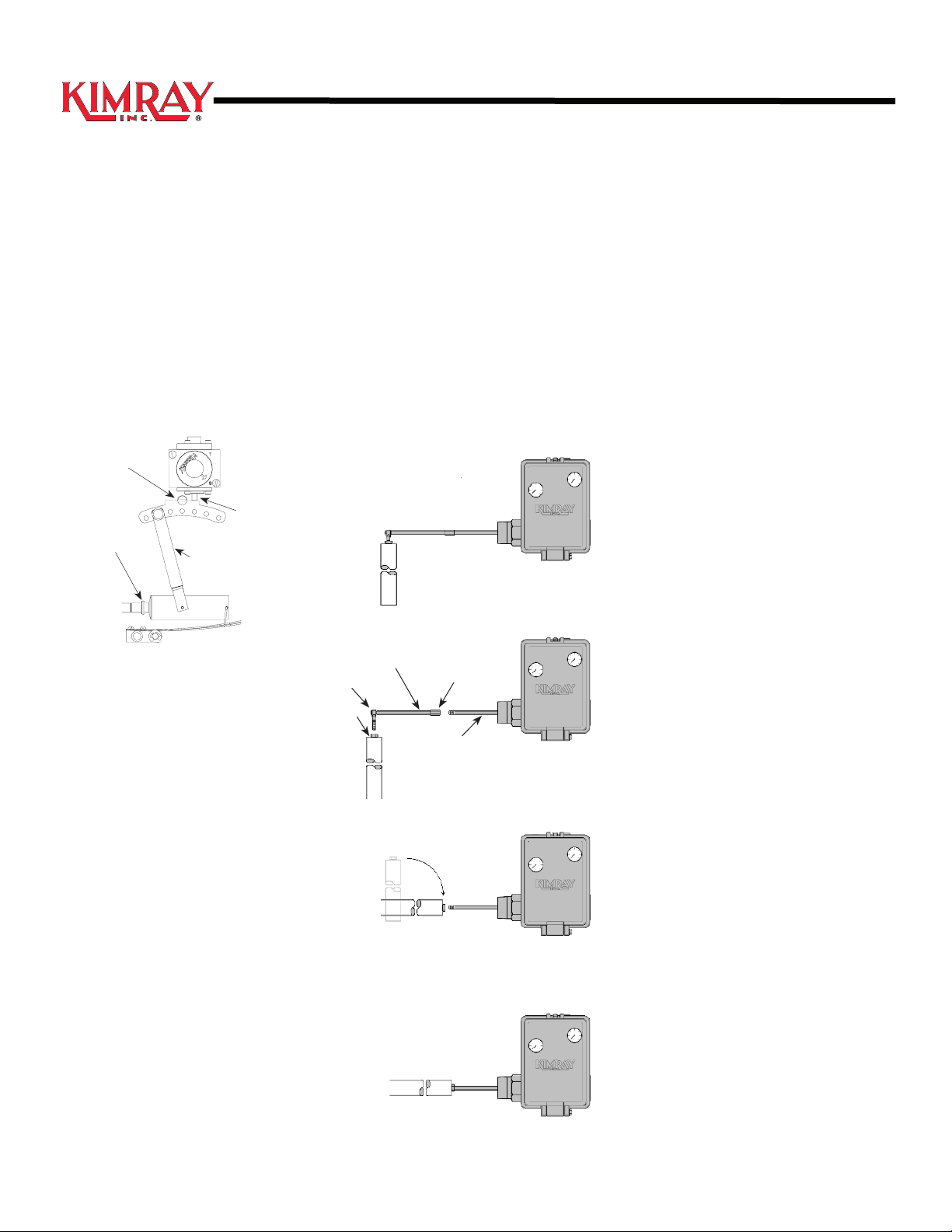
Horizontal Displacer Installation
The level controllers are shipped with the
vertical adapter attached to the displacer. To
mount the displacer for horizontal service.
1. Remove displacer from hanger block.
2. Remove extension rod and coupling from
terminal arm.
3. Thread the displacer all the way onto
threads of terminal arm.
Standard Verticle
Figure 2
Installation
CAUTION
Do not pick up or carry the controller by
using the displacer arm as a handle.
NPT Connection: Apply TFE tape or
pipe compound to the male threads of the
threaded body, or use appropriate gaskets
for a anged body. When installing a
threaded body, tighten sufciently to seal the
threads. Use a wrench on the ats of the
body. Do not use the pilot case to tighten
the connection. Make sure the pilot case is
vertical when nished.
Flanged Connection: Flanged controllers
are available on request. Use a suitable
gasket between the body and the vessel
connection ange.
Note
Remove the plastic plugs from the 1/4” NPT
openings. 1/4” or 3/8” tubing not provided
must be installed.
1. SUPP - Connect to a source of clean, dry
instrument gas.
Figure 1
Hanger Block
As the actuator travels in response to
force from the tangent arm, it continually
respositions a small three-way valve the
pilot plug and seats which modulates the
output pressure. This output is most often
used to control diaphragm pressure in a
control valve. Proper function can best be
accomplished when the gas owing through
the pilot is clean and free of liquid.
CAUTION
If the level controller is installed on a vessel
that is to be shipped to a different location,
remove the displacer and rod extensions
before shipment. Failure to do so could
result in damage to the displacer, the
displacer rod, or even to the pilot, due to
vibration and impact during shipment. After
the vessel is in its nal location, reassemble
the displacer and displacer rod extension.
Note
Check clearances to be sure there are no
obstructions inside the tank that will interface
with displacer installation or operation.
Displacer
Extension Rod
Terminal Arm
Remove
Figure 3
Horizontal
Coupling
Install
Figure 4
2. OUTPUT - Connect to the diaphragm
housing on the control valve being
operated.
3. VENT - Connect to a preferred location
for vented supply gas, or to a vapor
recovery system.
Changing Controller Mode or Action
CAUTION
To avoid personal injury caused by a sudden
release of pressure, shut off the instrument
gas supply pressure and bleed pressure
from the supply lines before performing any
change between snap and throttle mode.
Final
Figure 5
2
Float Operated Level Controllers
VE
PC
Models Pneumatic GEN II
Installation and Maintenance
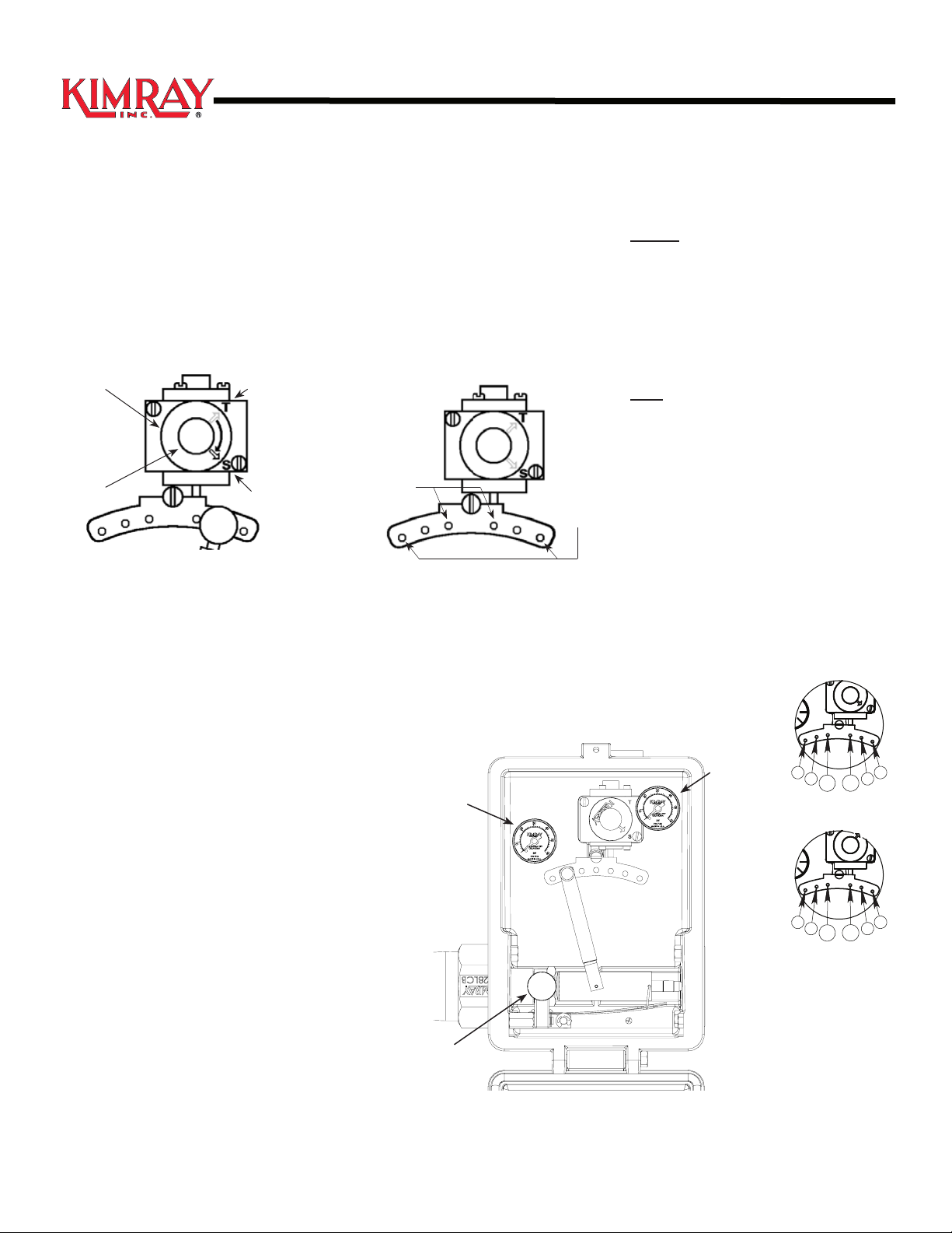
Changing Mode
The mode is selected with the switch plate.
After shutting off and venting instrument
gas pressure, loosen the selector knob
approximately one half turn. Then turn the
switch plate to “T” for throttle mode, or “S” for
snap mode. Then tighten selector knob.
Switch
Plate
Slector
Knob
Throttle
Setting
Snap
Setting
Figure 6
Changing Action
1. Refer to the following diagram to
determine the proper orientation of parts
for the desired action direct or indirect.
CAUTION
Liquids, with specic gravity less than 1.0 it
is best to set the link for the most sensitive
response. This will result in less span.
Calling for greater spans with low specic
gravity can cause span to exceed the length
of the displacer, resulting in loss of control.
Low
Sensitivity
(Large Span)
High
Sensitivity
(Small Span)
Figure 7
Snap Operation Span Adjustment
1. Refer to the following diagram above to
determine the proper orientation of parts
for the desired span.
Start-Up
Throttle- (No liquid on displacer)
PO Valve: At 0 psig turn adjusting knob
counter clockwise to produce 10 psig, then
turn clockwise one turn to 0 psig.
PC Valve: At 0 psig turn adjusting knob
clockwise to produce 20 to 30 psig.
Snap- (No liquid on displacer)
PO Valve: At 0 psig turn adjusting knob
clockwise to snap ON, then turn clockwise
two turns to 0 psig.
PC Valve: At 20 to 30 psig turn adjusting
knob counter clockwise to snap OFF, then
turn clockwise two turns from 20 to 30 psig.
Interface:
Cover displacers with the lighter uid.
Heavier uid must be below the displacer.
Then adjust same as above.
PROPORTIONAL BAND
SNAP MODE
2. Pull out the link knob, then move it to the
desired setting and press into hole.
Snap Setup Throttle Setup
Left of pivot for PC valve
Right of pivot for PO valve
Figure 8
Right of pivot for PC valve
Left of pivot for PO valve
Figure 9 Figure 10
2. Pull out the link knob, move to the desired
setting and press into hole.
Output
Guage
Level
Adjusting
Knob
Clockwise to raise level
Counter Clockwise to lower level
Supply
Guage
S
5" 5"
7" 7"
PC VALVE
PROPORTIONAL BAND
2" 2"
PO VAL
10"10"
PO VALVE
THROTTLE MODE
3" 3"
5"5"
S
VALVE
3
 Loading...