

Page 1

Page 2

Page 3

I. INTRODUCTION
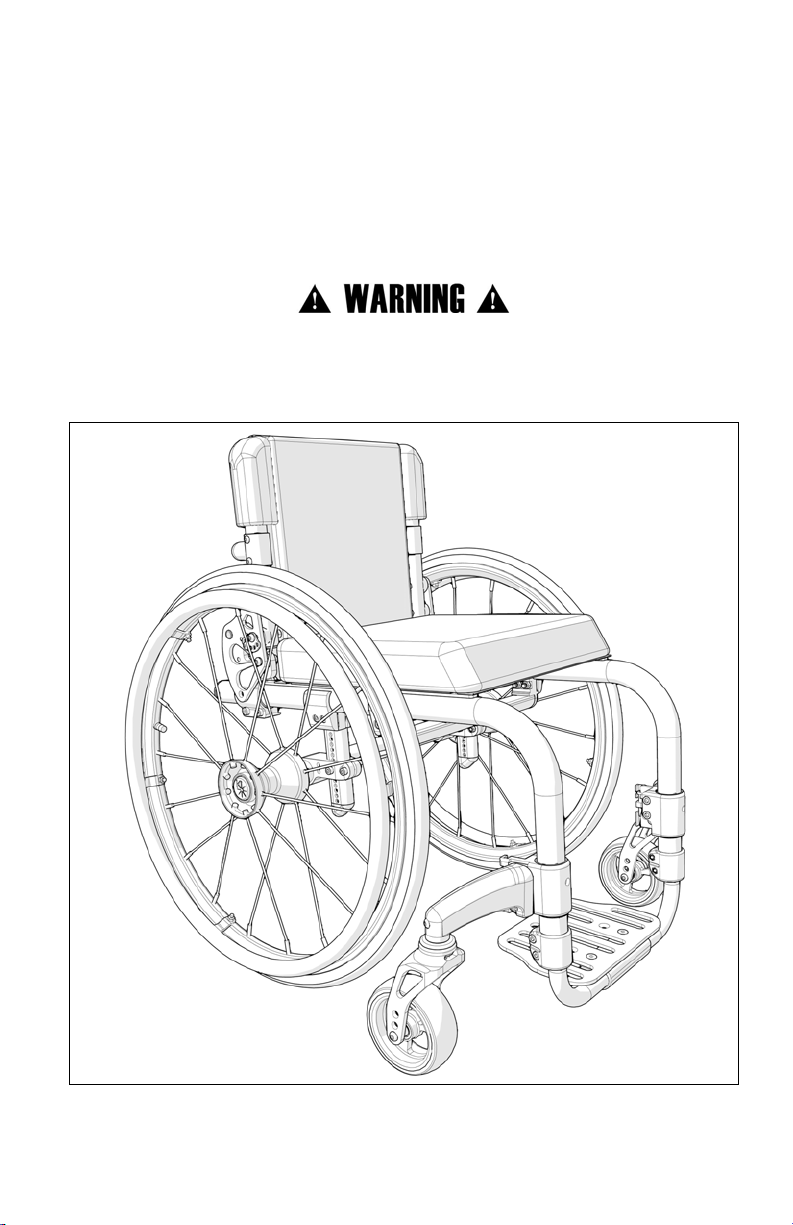
Thank you for purchasing a Little Wave “Clik” XP or Little
Wave “Clik” XPe wheelchair!
Please do not use this wheelchair without first reading this entire manual. BEFORE
riding, you should be trained in the safe use of this chair by an Assistive Technology
Practitioner (ATP) or clinical professional.
If you have any questions or concerns about any aspect of this wheelchair, this manual,
or the service provided by us or your retail supplier, please do not hesitate to contact
us by telephone at:
715-254-0991
In writing at:
Ki Mobility
5201 Woodward Drive
Stevens Point, WI 54481
U.S.A
Via email at:
sales@kimobility.com
Or via our Authorized EU Representative:
James Leckey Design
19C Ballinderry Road
Lisburn
BT28 2SA
Phone: 0800 318265 (UK) or 1800 626020 (ROI)
www.leckey.com
1
Page 4

II. TABLE OF CONTENTS
La Versión en Español comienza en la página 59
I. INTRODUCTION
II. TABLE OF CONTENTS
III. NOTICE - READ BEFORE USE
A. Your Safety and Stability ..................................................................... 4
IV. WARNINGS
A. Signal Words....................................................................................... 5
B. General Warnings................................................................................ 6
C. Positioning Belts ................................................................................. 7
D. Riding Your Wheelchair ....................................................................... 8
E. Power Drives....................................................................................... 9
F. Ascending Stairs ................................................................................. 9
G. Descending Stairs............................................................................... 9
H. Transfers............................................................................................. 10
I. Your Wheelchair and the Environment................................................. 10
J. Modifying your Wheelchair .................................................................. 11
K. Wheelchair Stability ............................................................................. 11
V. SET UP & USE OF YOUR WHEELCHAIR
A. Your Little Wave Clik & It’s Parts ......................................................... 14
B. Transit Use.......................................................................................... 15
C. Height-Adjustable T-Arms ................................................................... 18
D. Padded Swing-Away Adjustable Armrests .......................................... 19
E. Pediatric T-Arm Adjustment ................................................................ 20
F. Angle Adjustable Locking Flip Up Extendable Armrest......................... 20
G. Armrest Warnings ............................................................................... 21
H. Center of Gravity Adjustment .............................................................. 21
I. Wheel Camber .................................................................................... 23
J. Wheelbase Width Adjustment ............................................................. 24
K. Setting Toe to Zero ............................................................................. 25
L. Removing the Camber Tube ............................................................... 26
M. Replacing the Camber Tube................................................................ 27
N. Front Seat Height Adjustments............................................................ 29
O. Clik - Rear Seat Height Adjustment..................................................... 31
P. Caster Angle Adjustment..................................................................... 32
Q. Wheel Installation & Removal............................................................... 33
R. Adjusting the Footrest ......................................................................... 34
S. Optional Angle Adjustable Footplate.................................................... 34
T. Folding Backrest ................................................................................. 35
U. Backrest Angle Adjustment ................................................................. 35
V. Adjusting Backrest Height ................................................................... 37
W. Adjusting, Removing and Replacing Backrest Release Cable for Width
Growth ............................................................................................... 38
2
Page 5

II. TABLE OF CONTENTS
X. Adjusting Backrest Position................................................................. 39
Y. Removing Adjustable Backrest Rigidizer Bar for Width Adjustment...... 40
Z. Installing Adjustable Backrest Rigidizer Bar ......................................... 41
AA. Wheel Locks ....................................................................................... 42
AB. Growing Your Clik in Width.................................................................. 43
BB. Anti-Tips ............................................................................................. 44
CC. Cushion Installation ............................................................................. 46
DD. Upholstery Fabric ................................................................................ 46
EE. Adjusting and/or Growing Your Seat Upholstery.................................. 47
FF. Clik - Standard 5th Wheel (Optional).................................................... 49
GG. Clik - Dynamic 5th Wheel (Optional) .................................................... 50
HH. Adjusting Cross Tube and Armrest/Sideguard Position on Frame........ 52
II. Replacing Cross Tube for Width Adjustment ....................................... 52
JJ. Clik - High Mount Flip Under Footrest (Optional).................................. 53
VI. MAINTENANCE
A. Inspecting Your Wheelchair................................................................. 55
B. Cleaning Your Clik Wheelchair............................................................. 57
C. Storage............................................................................................... 57
VII. WARRANTY ................................................................................................. 58
3
Page 6

III. NOTICE - READ BEFORE USE
A. Your Safety and Stability
Ki Mobility manufactures many different wheelchairs that might meet your needs. You should
consult an Assistive Technology Professional when selecting which model would best meet
your particular requirements and how the wheelchair should be set up and adjusted. Final
selection of the type of wheelchair, options and adjustments rests solely with you and your
medical professional. The options you choose and the set-up and adjustment of the
wheelchair have a direct impact on its stability. Factors to consider that affect your safety and
stability are:
a. Your personal abilities and capabilities including strength, balance and coordination.
b. The types of hazards and obstacles you might encounter during your day.
c. The specific dimensions, options and set up. In particular, the seat height, seat depth,
seat angle, back angle, size and position of the rear wheels and size and position of the
front casters. Any change to any of these items will change the stability of your
wheelchair. You should only make changes after consulting with a qualified
professional.
4
Page 7

IV. WARNINGS
A. Signal Words
Within this manual you will find what are referred to as “Signal” words. These words are used
to identify and convey the severity of varying hazards. Before using this chair you, and each
person who may assist you, should read this entire manual. Please note the Signal word and
consider any warnings, cautions or dangers. Make sure to follow all instructions and use your
chair safely. The Signal word refers to a hazard or unsafe practice that may cause severe injury
or death to you or to other persons. The “Warnings” are in three main categories, as follows:
DANGER – Danger indicates an imminently hazardous situation which, if not avoided, will
result in serious injury or death.
WARNING – Warning indicates a potentially hazardous situation which, if not avoided, could
result in serious injury or death.
CAUTION – Caution indicates a potentially hazardous situation which, if not avoided, could result in injury or damage to your wheelchair.
These signal words will be placed throughout the manual, where appropriate to highlight the
hazardous situation. Refer to the following list for hazardous situations that will apply to the
general use of this wheelchair.
5
Page 8

IV. WARNINGS
B. General Warnings
WARNING: Do not exceed the weight limit of 165 pounds for the Little Wave Clik. This is the
combined weight of user and all items carried. Exceeding the weight limit can cause damage
to your chair or increase the likelihood of a fall or tip back resulting in severe injury or death to
the user or others.
DANGER: Do not use this chair for weight training. The movement of the additional weight
will alter the center of gravity of the wheelchair increasing the likelihood of a tip-over which
can cause damage to your chair or cause severe injury or death to the user or others.
WARNING: If your wheelchair is equipped with inflatable tires, make sure the tires have
been inflated to the correct tire pressure as indicated on the side wall of the tire. Your
wheelchair provider can determine if you have inflatable tires. Using your wheelchair without
properly inflated tires can have an effect on the stability of the wheelchair causing it to tip over
resulting in death or injury to the user or others.
DANGER: Do not attempt to push your wheelchair up or down ramps or traverse across a
slope of greater than 9 degrees. This is dangerous and increases the likelihood of a fall or tip
back resulting in severe injury or death to the user or others.
WARNING: Do not attempt to push your wheelchair up an incline that is slick or coated
with ice, oil or water. This can cause an unstable situation resulting in death or injury to the
user or others.
DANGER: Do not lean over the side or back of the wheelchair to extend your reach. This
may cause you to fall out of the wheelchair or the wheelchair to tip over resulting in injury or
death.
6
Page 9

IV. WARNINGS
B. General Warnings
DANGER: Do not attempt to the lift the wheelchair by holding on to removable parts such
as the arms or footrests. Only lift the wheelchair by holding on to the frame. This may cause a
fall or loss of control and result in serious injury or death.
CAUTION: Do not overtighten the bolts and hardware that attaches various components together on the frame.
the wheelchair.
C. Positioning Belts
Positioning belts are designed to assist with proper positioning within the wheelchair. They are
not designed as seat belts. Use positioning belts ONLY to help support the user’s posture.
Misuse of positioning belts may cause severe injury to or death of the user.
• Ensure the user does not slide underneath the positioning belt in the wheelchair seat. If
this occurs, the user’s breathing may be hampered causing death or serious injury.
• The positioning belt should have a snug fit; tight enough to hold their position, but not
so tight as to restrict breathing. You should be able to slide your hand between the
positioning belt and the user.
• NEVER Use Positioning Belts:
a. As a restraint. A restraint requires a doctor’s order.
b. On a user who is unconscious.
c. As an occupant restraint in a motor vehicle. A positioning belt is not designed to
replace a seat belt that is attached to the frame of a vehicle, which would be required
of an effective seat belt. During a sudden stop, with the force of the stop, the user
would be thrown forward. Wheelchair seat belts will not prevent this, and further
injury may result from the belts or straps.
This could cause serious damage and affect the safety and durability of
DANGER: Failure to comply with the instruction above could result in serious injury or death.
7
Page 10

IV. WARNINGS
D. Riding Your Wheelchair
Your chair is designed for use on solid, flat surfaces such as concrete, asphalt and flooring.
Use caution if you push your wheelchair on a wet or slick surface.
WARNING: Do not push your chair in sand, loose soil or over rough terrain. This may cause
a loss of stability and result in a fall or loss of control and cause serious injury or death.
DANGER: In most states, wheelchairs are not legal for use on public roads. If you find you
must push on a public road, be alert to the danger of motor vehicles. Use of a wheelchair on a
public road can cause serious injury or death.
WARNING: Obstacles and road hazards (such as potholes and broken pavement) can
damage your chair and may cause a fall, tip-over or loss of control. Failure to comply with
this instruction could result in serious injury or death.
DANGER: Do not ride your wheelchair on an escalator. Use of a wheelchair on an escalator
can cause serious injury or death.
To minimize these risks:
1) Keep a lookout for danger-scan the area well ahead of your chair as you ride.
2) Make sure the floor areas where you live and work are level and free of obstacles.
3) Remove or cover threshold strips between rooms.
4) Install a ramp at entry or exit doors. Make sure there is not a drop off at the bottom
of the ramp.
5) To Help Correct Your Center of Balance:
a. Lean your upper body FORWARD slightly as you go UP over an obstacle.
b. Press your upper body BACKWARD as you go DOWN from a higher to a
lower level.
6) If your chair has anti-tip tubes, lock them in place before you go UP over an obstacle.
7) Keep both of your hands on the handrims as you go over an obstacle.
8) Never push or pull on an object (such as furniture or a doorjamb) to propel your
chair.
9) Do not operate your wheelchair on roads, streets or highways.
10) Do not attempt to push over obstacles without assistance.
8
Page 11

IV. WARNINGS
E. Power Drives
Ki Mobility does not recommend the installation of power drive systems on any Little Wave
Clik wheelchair.
Little Wave Clik wheelchairs have not been designed or tested as power wheelchairs. If you
add a power drive system to a Little Wave Clik wheelchair, be sure the manufacturer of the
power drive system has validated and approved the combination of the power drive system
and Little Wave Clik wheelchair as safe and effective.
WARNING: Use of a power drive system that has not been properly validated could result
in serious injury or death.
F. Ascending Stairs
• Have at least two people, who have sufficient strength and skill to handle the weight of
the user and wheelchair, assist when trying to go up a set of stairs in this wheelchair.
• Move the wheelchair and user backwards up the stairs.
• Position one person behind the user, one person in front. The person in front must hold
onto a non-removable part of the wheelchair.
• The rear attendant tilts the chair back and they both lift together. Take one step at a
time.
• This may require the anti-tips be flipped up or removed. Make sure the anti-tips are
reattached or flipped back down before using the wheelchair.
DANGER: Failure to comply with the instructions above could result in serious injury or death.
G. Descending Stairs
• When descending a set of stairs the user should be facing forward.
• A person behind the user, who has sufficient strength and skill to handle the weight of
the user and the wheelchair, should tilt the chair backward and let the chair down the
stairs one step at a time on the rear wheels.
• This may require that anti-tips be flipped up or removed. Make sure the anti-tips are
reattached or flipped back down before using the wheelchair.
DANGER: Failure to comply with the instructions above could result in serious injury or death.
9
Page 12

IV. WARNINGS
H. Transfers
A transfer requires good balance and stability. You should receive training from your therapist
before attempting to do a transfer on your own.
• Before transferring out of your wheelchair every caution should be taken to reduce the
gap between the two surfaces.
• Engage the wheel locks to lock the rear wheels.
• Rotate the casters forward to increase the wheelbase of the wheelchair.
• Remove or swing away the footrests.
• Have someone assist you unless you are well experienced in transfers.
It is dangerous to transfer on your own. It requires good balance and agility. Be aware there is
a point during every transfer when the wheelchair seat is not below you.
WARNING: Failure to comply with the instructions above may cause a fall or loss of
control, which may result in serious injury or death.
I. Your Wheelchair and the Environment
• Your wheelchair is made of many different materials including metal and fabric.
Exposure to water or excessive moisture may cause the metal in the wheelchair to rust
or corrode and the fabric to tear. Dry your chair as soon as possible if exposed to water.
• DO NOT USE YOUR WHEELCHAIR IN A SHOWER, POOL OR BODY OF WATER. This
will cause your wheelchair to rust or corrode and eventually fail.
• Do not operate your wheelchair in sand. Sand can get into the wheel bearings and
moving parts. This will cause damage and eventually will cause the wheelchair to fail.
• Make sure any ramp, slope or curb cut you may attempt to ride on is compliant with
ADA guidelines. Riding across, up or down any slope that is too great may cause a loss
of stability.
ADA Guidelines and more information about accessible design are available at:
http://www.ada.gov/
WARNING: Failure to comply with the instructions above may cause a fall or loss of
control, which may result in serious injury or death.
10
Page 13

IV. WARNINGS
J. Modifying your Wheelchair
Your wheelchair was engineered and manufactured under strict design controls. An integral
part of this process is ensuring the various components work together correctly; they have
been tested to various standards to ensure quality and are approved to work together.
YOU SHOULD NOT CHANGE, ADD OR REMOVE COMPONENTS OR OTHERWISE MODIFY
THIS WHEELCHAIR. NO ONE SHOULD MODIFY THIS WHEELCHAIR EXCEPT BY
ASSEMBLING APPROVED OPTIONS. THERE ARE NO APPROVED OPTIONS THAT INVOLVE
DRILLING OR CUTTING THE FRAME BY ANYONE OTHER THAN A TRAINED KI MOBILITY
ASSOCIATE. Contact Ki Mobility or an authorized Ki Mobility supplier before adding any
accessories or components not provided by Ki Mobility.
DANGER: Failure to comply to these instructions may cause the wheelchair to fail and result
in serious injury or death.
K. Wheelchair Stability
To ensure proper stability of your wheelchair, you must make sure the center of gravity and the
wheelchairs base of support is correct for your balance and abilities. Many factors can affect
these two elements:
• Seat height
•Seat depth
•Back angle
Generally, the most important factor is the position of the rear wheels for rearward stability.
There are other actions than can have an adverse effect on your stability. You should consult
with your wheelchair provider and clinicians familiar with your needs and capabilities in
determining how this affects your use.
WARNING: Moving the rear wheels forward increases the likelihood of the wheelchair
tipping backwards. Make small adjustments and proceed slowly until you learn the new
balance point of your wheelchair. Failure to comply with the instruction above could result in
serious injury or death.
• Size and position of rear wheels
• Size and position of front casters
• Any seating system components
11
Page 14

IV. WARNINGS
K. Wheelchair Stability
WARNING: The farther rearward you place the front casters the greater the likelihood of
the wheelchair tipping forwards. If possible, have your casters mounted forward and
whenever doing a static activity which involves shifting your weight, rotate the casters forward
to increase your wheel base. Failure to comply with this instruction above could result in
serious injury or death.
WARNING: Always have a qualified technician set up your wheelchair with the accessories
you plan to use daily.
Changes to how you sit or changes in your weight require your chair to be readjusted by a
qualified technician. Always use anti-tips while you acclimate to any changes in your chair set
up. Failure to comply with the instruction above could result in serious injury or death.
WARNING: Changes to your Center of Gravity during your daily activities may occur many
times a day, changing and affecting the stability of your wheelchair. You should be aware of
these activities and take precautions to minimize the risk of a fall. Failure to comply with
the instruction above could result in serious injury or death.
WARNING: Dressing in your wheelchair produces movements and momentary positions that
can reduce stability. Ensure that your anti-tips are in place and rotate your casters forward.
Failure to comply with the instruction above could result in serious injury or death.
WARNING: Be very careful when reaching for objects if this movement requires you to shift
in your seat. This changes your center of gravity. Ensure that your anti-tips are in place.
Failure to comply with the instruction above could result in serious injury or death.
WARNING: Pushing up an incline shifts your center of gravity rearward and can reduce
stability. Ensure your anti-tips are in place. Failure to comply with the instruction above
could result in serious injury or death.
12
Page 15

IV. WARNINGS
K. Wheelchair Stability
WARNING: If attempting a wheelie to get over a curb or obstacle, ensure your anti-tips are in
place and lean forward. Do not attempt a wheelie unless you have been trained and always
have an attendant behind you to provide assistance if needed. Failure to comply with the
instruction above could result in serious injury or death.
WARNING: Placing items on the back or front of your wheelchair, such as a backpack or
briefcase, alters the balance and center of gravity of the wheelchair. Since the weight of
these items can vary greatly at each use do not assume you are accustomed to the balance
point. Failure to comply with the instruction above could result in serious injury or death.
BE AWARE THAT CARRYING HEAVY OBJECTS ON YOUR WHEELCHAIR CAN HAVE AN
ADVERSE EFFECT ON THE BALANCE WHICH MAY CAUSE A TIP-OVER WHICH MAY
RESULT IN SERIOUS INJURY OR DEATH TO THE USER.
WARNING: Ensure your anti-tips are in place. You should discuss how you plan to use your
wheelchair or any changes you are planning with your clinician. Failure to comply with this
instruction may create a potential hazardous situation which, if not avoided, could result in
serious injury or death.
13
Page 16
V. SET UP & USE OF YOUR WHEELCHAIR
A. Your Little Wave Clik & It’s Parts
1. Inspect and maintain this chair. See MAINTENANCE on page 55.
2. If you detect a problem, make sure to service or repair the chair before use.
3. Have a complete inspection, safety check and service of your chair performed by an
authorized supplier annually.
WARNING: Failure to read or comply with these instructions may result in damage to your
wheelchair, a fall, or loss of control causing severe injury to the user or others.
14
Page 17

V. SET UP & USE OF YOUR WHEELCHAIR
B. Transit Use
It is always safest to transfer out of your wheelchair onto a seat in a motor vehicle with appropriate
seat and shoulder belts. Never use this wheelchair as a seat in a motor vehicle unless it has
been equipped with the Transit Option.
The Little Wave Clik Series wheelchair equipped with the Transit Option has been tested to and
passed the RESNA WC-4:2012, Section 19: Wheelchairs used as seats in motor vehicles
and ISO 7176-19:2008 Wheelchairs -- Part 19: Wheeled mobility devices for use as seats in
motor vehicles. RESNA and ISO standards are designed to test the structural integrity of the
wheelchair as a seat for use in a motor vehicle. These standards are also designed to create
compatibility with Wheelchair Tie-down and Occupant Restraint Systems (WTORS).
Not all configurations of the Little Wave Clik Series wheelchairs are compatible with the Transit
Option. Ki Mobility manages the configuration and does not offer the Little Wave Clik Series
wheelchair except in compatible configurations. If you make changes to your Little Wave Clik
Series wheelchair after your receive it, you should contact your wheelchair provider or Ki Mobility
to make sure it is appropriate to continue to use your wheelchair as a seat in a motor vehicle.
If your Little Wave Clik Series wheelchair is equipped with the Heavy Duty Option and the Transit
Option you should not use it as a seat in a motor vehicle if you weigh more than 125 lbs.
Aftermarket seating may have replaced the original equipment seat and back support designed
and tested as part of the Transit Option. Your wheelchair provider should tell you if the seating they
provided is original equipment or replacement aftermarket seating. A complete system of
wheelchair frame, seating, Wheelchair Tie-down and Occupant Restraint Systems and a properly
equipped motor vehicle, that have all complied with the standards mentioned in this section,
should be in place before using a Little Wave Clik Series wheelchair equipped with the Transit
Option as a seat in a motor vehicle.
When using your wheelchair as a seat in a motor vehicle you should always observe the following
instructions:
• The rider must be in a forward-facing position.
• The rider and all items carried must not weigh more than 125 lbs.
• Backpacks and pouches should be removed and secured separately in the motor vehicle.
In the event of an accident these items can become dangerous projectiles, which may
injure or kill you or other occupants of the motor vehicle.
• The rider must use a Wheelchair Tie-down and Occupant Restraint System that complies
with RESNA WC-4:2012, Section 18: Wheelchair tie-down and occupant restraint
systems for use in motor vehicles or ISO 10542-1:2012 Technical systems and aids
for disabled or handicapped persons -- Wheelchair tie-down and occupant-restraint
systems -- Part 1: Requirements and test methods for all systems.
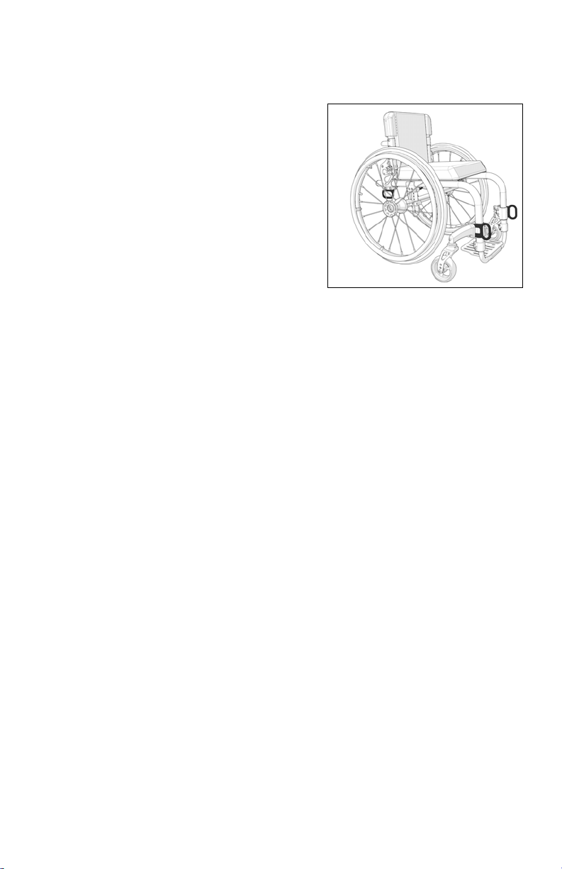
• Attach wheelchair tie-downs to the four securement points (two front, two rear) on the Little
Wave Clik Series wheelchair with the Transit Option Fig. 1 in accordance with the
wheelchair tie-down manufacturer’s instructions and RESNA WC-4:2012, Section 18 or
ISO 10542-1:2012 - Part 1.
• Attach occupant restraints in accordance with the occupant restraint manufacturer’s
instructions and RESNA WC-4:2012, Section 18 or ISO 10542-1:2012, Part 1.
15
Page 18
V. SET UP & USE OF YOUR WHEELCHAIR
Fig. 1
B. Transit Use (Continued)
• Use of lap belts, chest straps, shoulder
harnesses, any other positioning strap system or
positioning accessory should not be used, or
relied on as an occupant restraint, unless it is
marked as such by the manufacturer in
accordance with RESNA WC-4:2012, Section
18 or ISO 10542-1:2012, Part 1.
• Use of headrests, lateral supports or other
positioning accessories should not be used, or
relied on as an occupant restraint, unless it is
marked as such by the manufacturer in
accordance with RESNA WC-4:2012, Section
18 or ISO 10542-1:2012, Part 1 or RESNA WC-4:2012, Section 20: Wheelchair
seating systems for use in motor vehicles or ISO 16840-4:2009 Wheelchair seating -Part 4: Seating systems for use in motor vehicles.
• After being fitted and adjusted, the top of the original equipment back upholstery should be
within 3 inches of the top of your shoulder.
• Any aftermarket seating should be tested to comply with RESNA WC-4:2012, Section 20
or ISO 16840-4:2009 - Part 4.
• Attach the seating to the wheelchair frame in accordance with the seating manufacturer’s
instructions and RESNA WC-4:2012, Section 20 or ISO 16840-4:2009 - Part 4.
• Use of lap belts, chest straps, shoulder harnesses, any other positioning strap system or
positioning accessory should not be used, or relied on as an occupant restraint, unless it is
marked as such by the seating manufacturer in accordance with RESNA WC-4:2012,
Section 20 or ISO 16840-4:2009 - Part 4.
• Use of headrests, lateral supports or other positioning accessories should not be used, or
relied on as an occupant restraint, unless it is marked as such by the seating manufacturer
in accordance with RESNA WC-4:2012, Section 20 or ISO 16840-4:2009 - Part 4.
• Aftermarket accessories such as trays, oxygen tank holders, oxygen tanks, IV poles, back
packs, pouches and other items not manufactured by Ki Mobility should be removed and
secured separately in the motor vehicle. In the event of an accident, these items can
become dangerous projectiles which may injure or kill you or other occupants of the motor
vehicle.
• If the wheelchair has been involved in an accident, you should not continue to use it, as it
may have suffered fatigue that may not be visible.
16
Page 19

V. SET UP & USE OF YOUR WHEELCHAIR
B. Transit Use (Continued)
DANGER: Failure to comply with transit use instructions, on pages 15 and 16, could result in
severe injury or death!
NOTE: To obtain copies of RESNA or ISO standards please contact the standards organizations
below:
RESNA
1700 North Moore St., Suite 1540
Arlington, VA 22209
Phone: 703-524-6686
Fax: 703-524-6630
Email: technicalstandards@resna.org
ANSI/RESNA Standards:
RESNA WC-4:2012, Section 18:
Wheelchair tie-down and occupant restraint systems for use in motor vehicles.
RESNA WC-4:2012, Section 19:
Wheelchairs used as seats in motor vehicles.
RESNA WC-4:2012, Section 20:
Wheelchair seating systems for use in motor vehicles.
International Organization for Standardization (ISO)
ISO Central Secretariat
BIBC II
Chemin de Blandonnet 8
CP 401
1214 Vernier, Geneva
Switzerland
Phone: +41 22 749 01 11
Fax: +41 22 733 34 30
Email: central@iso.org
ISO Standards:
ISO 10542-1:2012 Technical systems and aids for disabled or handicapped person --
Wheelchair tie-down and occupant-restraint systems -- Part 1:
Requirements and test methods for all systems.
ISO 16840-4:2009 Wheelchair seating -- Part 4:
Seating systems for use in motor vehicles.
ISO 7176-19:2008 Wheelchairs -- Part 19:
Wheeled mobility devices for use as seats in motor vehicles.
17
Page 20
V. SET UP & USE OF YOUR WHEELCHAIR
Fig. 2
A
B
C
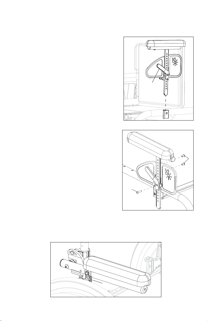
C. Height-Adjustable T-Arms
1. Installation
a. Slide the outer armpost into the receiver mounted to the wheelchair frame.
b. The armrest will automatically lock into place. Check to make sure the locking lever is as
shown (Fig. 2:C).
2. Height Adjustment
a. Rotate release lever (Fig. 2:A).
b. Slide armrest pad up or down to desired height.
c. Return lever to locked position against arm post.
d. Push arm pad until upper arm post locks firmly into place. Check to make sure the locking
lever is as shown (Fig. 2:A).
3. Removing Armrest
a. Squeeze release lever (Fig. 2:B) and remove the armrest.
4. Replacing Armrest
a. Slide armrest back into receiver.
b. The armrest should lock back into place.
DANGER: Failure to comply with the instructions above may result in the armrest accidentally
disconnecting from the wheelchair and result in a fall or loss of control and may cause serious
injury or death.
DANGER: Never attempt to lift the chair by the armrests; they may break or disconnect resulting
in a fall or loss of control and may cause serious injury or death.
18
Page 21
V. SET UP & USE OF YOUR WHEELCHAIR
Fig. 3
A
B
C
Fig. 4
A
B
C
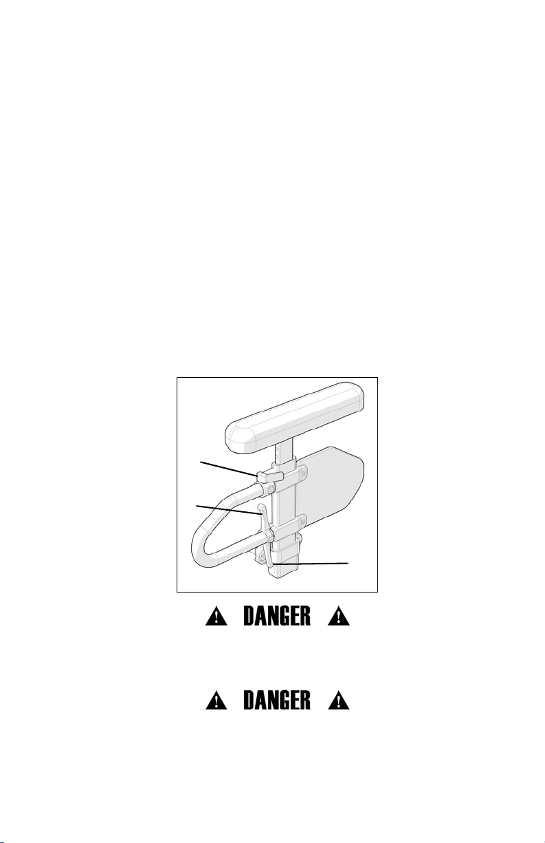
D. Padded Swing-Away Adjustable Armrests
1. Installation
a. Slide armrest into receiver tube on rear of frame.
Ensuring the pin engages the receiver.
2. Swinging Away
a. Lift armrest up until pin disengages from receiver and
rotate to the side.
3. Removing Armrest
a. Pull armrest straight out of receiver.
4. Adjusting Arm Height
a. Remove armrest from receivers.
b. From inside of backrest mount, remove 6mm screw
(Fig. 3:A) and remove threaded barrel (Fig. 3:B).
c. Select desired height and replace threaded barrel
(Fig. 3:B).
d. Reinsert 6mm screw (Fig. 3:A) into threaded barrel
and tighten.
e. Reinsert arm into receiver.
f. Retighten 6mm screw (Fig. 3:A).
g. Repeat on other armrest.
5. Adjusting Receiver Angle
a. From inside of backrest mount, loosen 6mm screw
(Fig. 4:A) and remove M5 screw (Fig. 4:B). You can
now adjust armrest to desired angle.
b. Once desired armrest angle is achieved realign
holes in pivot bracket (Fig. 4:C).
c. Reinsert M5 screw (Fig. 4:B) through locating holes
and tighten.
d. Retighten 6mm screw (Fig. 4:A).
DANGER: These arms offer only a lock against rotation and are designed to bear a downward
force only. They will remove completely if pulled up on and cannot be used to lift or otherwise
handle the chair. Failure to comply with the instructions above may result in the armrest
accidentally disconnecting from the wheelchair and result in a fall or loss of control and may cause
serious injury or death.
19
Page 22
V. SET UP & USE OF YOUR WHEELCHAIR
A
Fig. 5
A
B
Fig. 6
A
Fig. 7
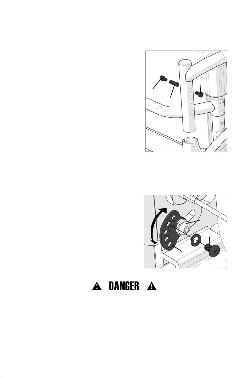
E. Pediatric T-Arm Adjustment
1. Installation
a. Slide armrest post into receiver on side frame.
Ensuring the pin in lever engages the receiver
Fig. 5.
2. Removing Armrest
a. Push lever (Fig. 5:A) in towards side guard panel to
release pin from receiver.
b. Pull armrest straight out of receiver.
3. Adjusting Arm Height in Receiver
a. Remove armrest from chair.
b. Remove two 6mm screws from side guards (Fig.
6:A).
c. Remove M4 screw (Fig. 6:B) from side guard post
stop through side guard post but do not pull
entirely out. Screw can stay in the lever assembly.
Repeat on other arm.
d. Reset the post stop and lever assembly on side
guard post to desired position. Retighten M4
screw (Fig. 6:B). Repeat on other arm.
e. Place side guard in desired position and replace
two 6mm screws (Fig. 6:A) to secure side guard in
place. Tighten two 6mm screws. Repeat on
opposite arm.
f. Replace armrest assemblies into receiver Fig. 5.
F. Angle Adjustable Locking Flip Up Extendable Armrest
Use
1. Press the release lever (Fig. 7:A) up to release the armrest and swing it upwards.To return the
armrest to the operating position, push the armrest down until the lever clicks and locks.
20
Page 23
V. SET UP & USE OF YOUR WHEELCHAIR
Fig. 8
B
A
G. Armrest Warnings
• All Ki Mobility armrests are designed to detach from the chair and will not bear the weight
of this chair.
• NEVER lift this chair by its armrests. The armrests will release and the user may fall.
• Lift this chair only by non-detachable parts of the main frame.
WARNING: Failure to heed these instructions may result in a fall, tip-over or loss of control
causing severe injury to the user or others.
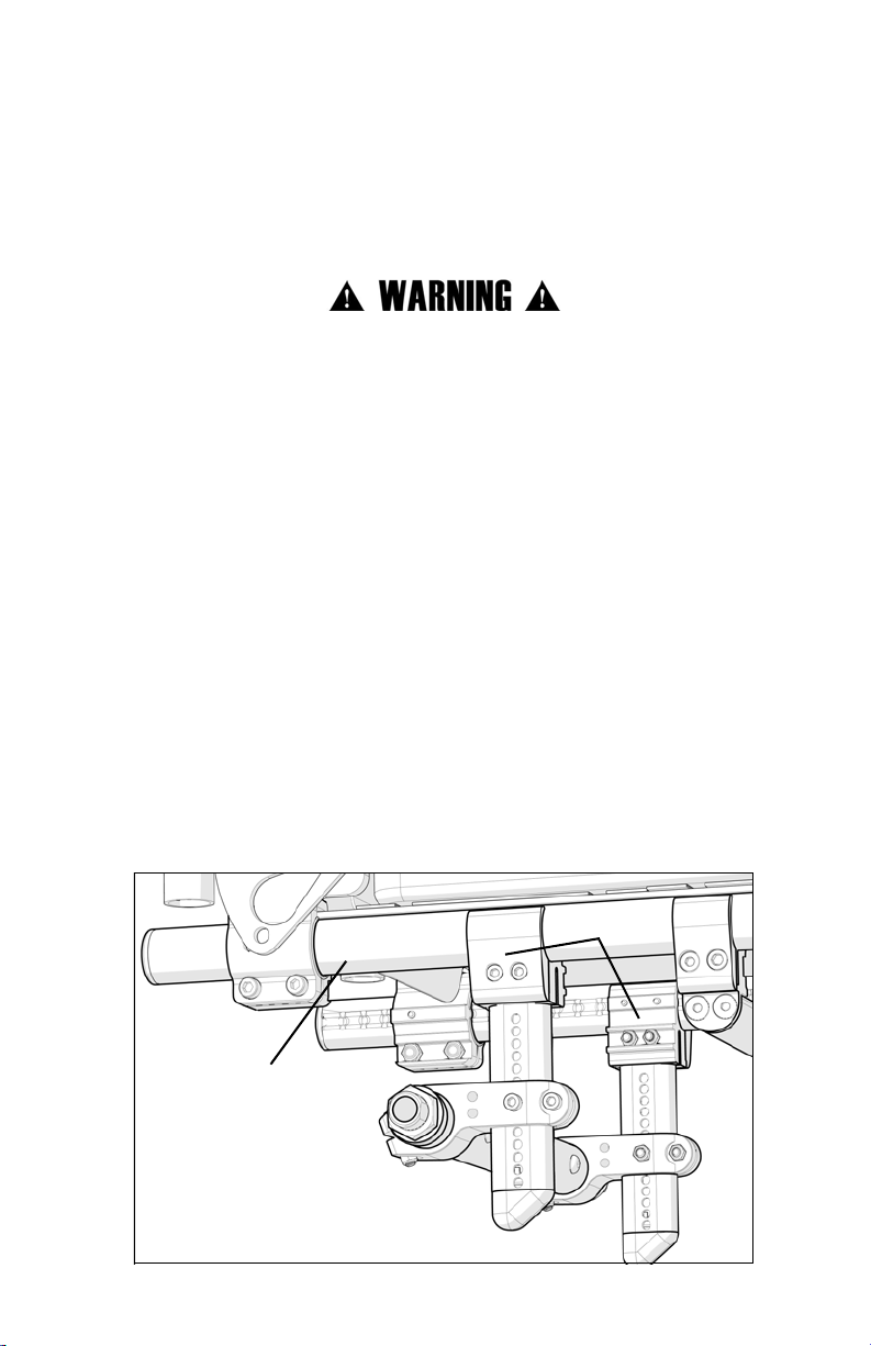
H. Center of Gravity Adjustment
The most important adjustment on your Clik wheelchair is the position of the rear axle.
You can adjust your center of gravity by moving the two camber mount clamps (Fig. 8:A) forward
or rearward on the seat tube (Fig. 8:B).
Moving the camber mount clamps forward shortens the wheelbase and lightens the front end,
making your chair more maneuverable. Moving the camber mounts rearward makes the chair
more stable and less likely to tip over rearward.
NOTE: Changes to the center of gravity may affect the rear seat height (see Clik - Rear Seat
Height Adjustment on page 31), toe-in / toe-out of the rear wheels (see Setting Toe to Zero on
page 25) and the squareness of the casters (see Caster Angle Adjustment on page 32). If you
change your center of gravity position, readjust all of these settings if necessary.
NOTE: Adjusting your chair’s center of gravity will require readjusting the location of the wheel
locks (if provided). See Growing Your Clik in Width on page 43 for instructions on adjusting the
wheel locks.
21
Page 24
V. SET UP & USE OF YOUR WHEELCHAIR
Fig. 9
B
C
A
D
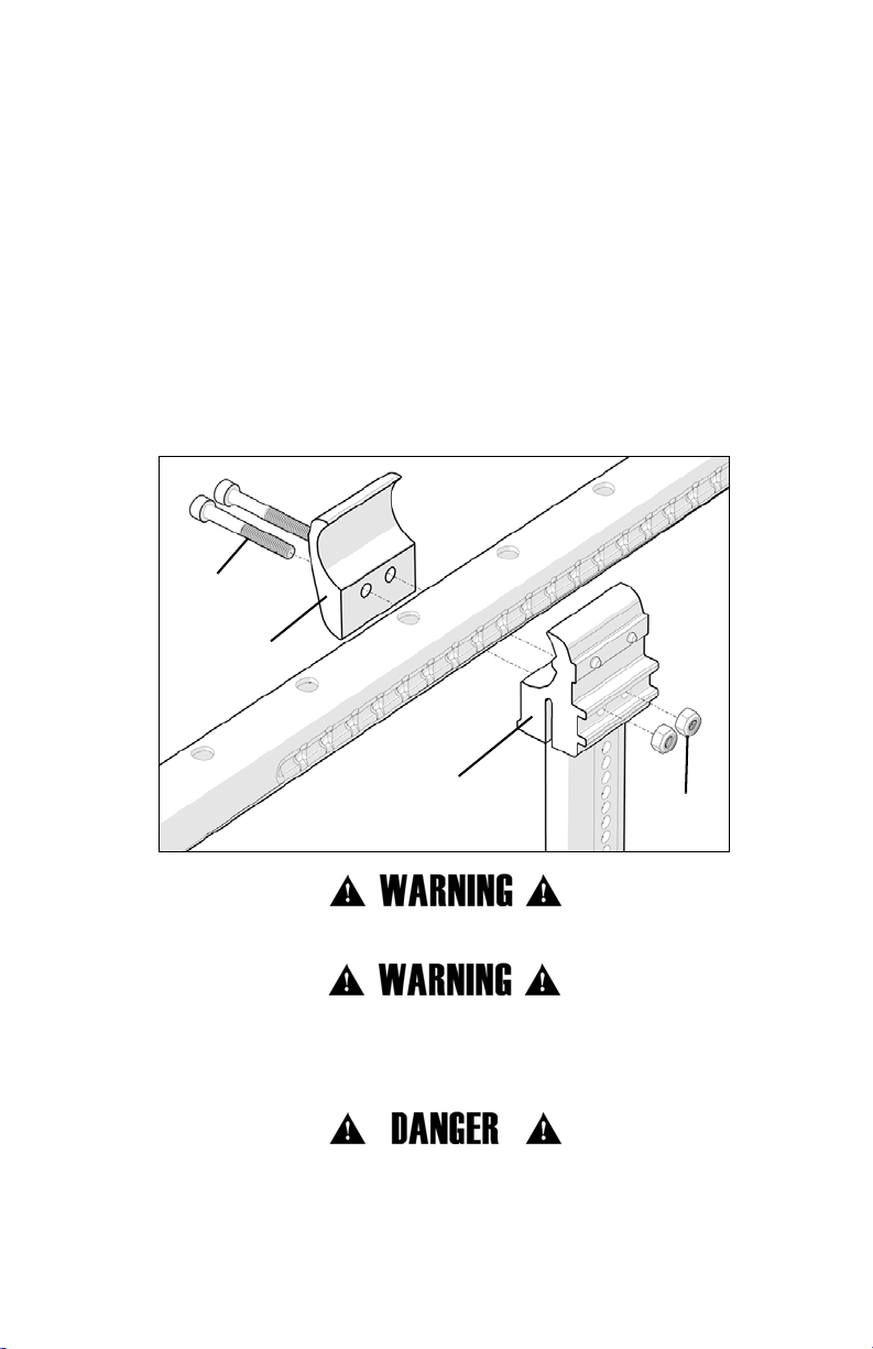
H. Center of Gravity Adjustment (Continued)
To adjust the center of gravity location:
a. Remove both rear wheels.
b. Loosen the two screws (Fig. 9:C) and nuts (Fig. 9:D) that secure the camber mounts (Fig.
9:A and B) to the seat tubes on each side of the frame.
c. Grasp both sides of the camber tube and move the camber mounts forward or rearward
along the seat tube. You should feel the detent click into each dimple in the frame as you
move the mounts forward or rearward. Adjustments are made in ¼" increments.
d. Make sure the mounts on both sides of the frame are adjusted equally on both sides of the
frame before reinserting screws and nuts. Tighten until secure.
e. Once the camber mount clamps are secured, attach the rear wheels, occupy the chair and
manuever it with a spotter to get a feel for the new adjustment.
WARNING: Always use at least two screws when attaching the camber mount to the frame.
WARNING: The more you move your rear wheels forward, the more likely your chair will tip over
backwards. Always make adjustments in small increments and check the stability of your chair
with a spotter to prevent a tip over. We recommend that you use anti-tip tubes until you adapt to
the change and are sure you are not at risk to tip over.
DANGER: Failure to heed these warnings may cause serious injury or death.
22
Page 25
V. SET UP & USE OF YOUR WHEELCHAIR
X°
Fig. 11
A
Fig. 10
Fig. 12
B
I. Wheel Camber
Wheel camber, shown as an angular relationship (Fig. 10 and Fig. 11:A), provides greater side-toside stability due to the increased width and angle of the wheelbase. It also allows for quicker
turning and greater access to the top of the handrims.
Wheel camber is determined by pairs of interchangeable camber adapters (Fig. 12:B) which are
available from your authorized supplier in 0°, 2°, 4°, 6°, and 8° angles.
23
Page 26
V. SET UP & USE OF YOUR WHEELCHAIR
Fig. 13
A
B
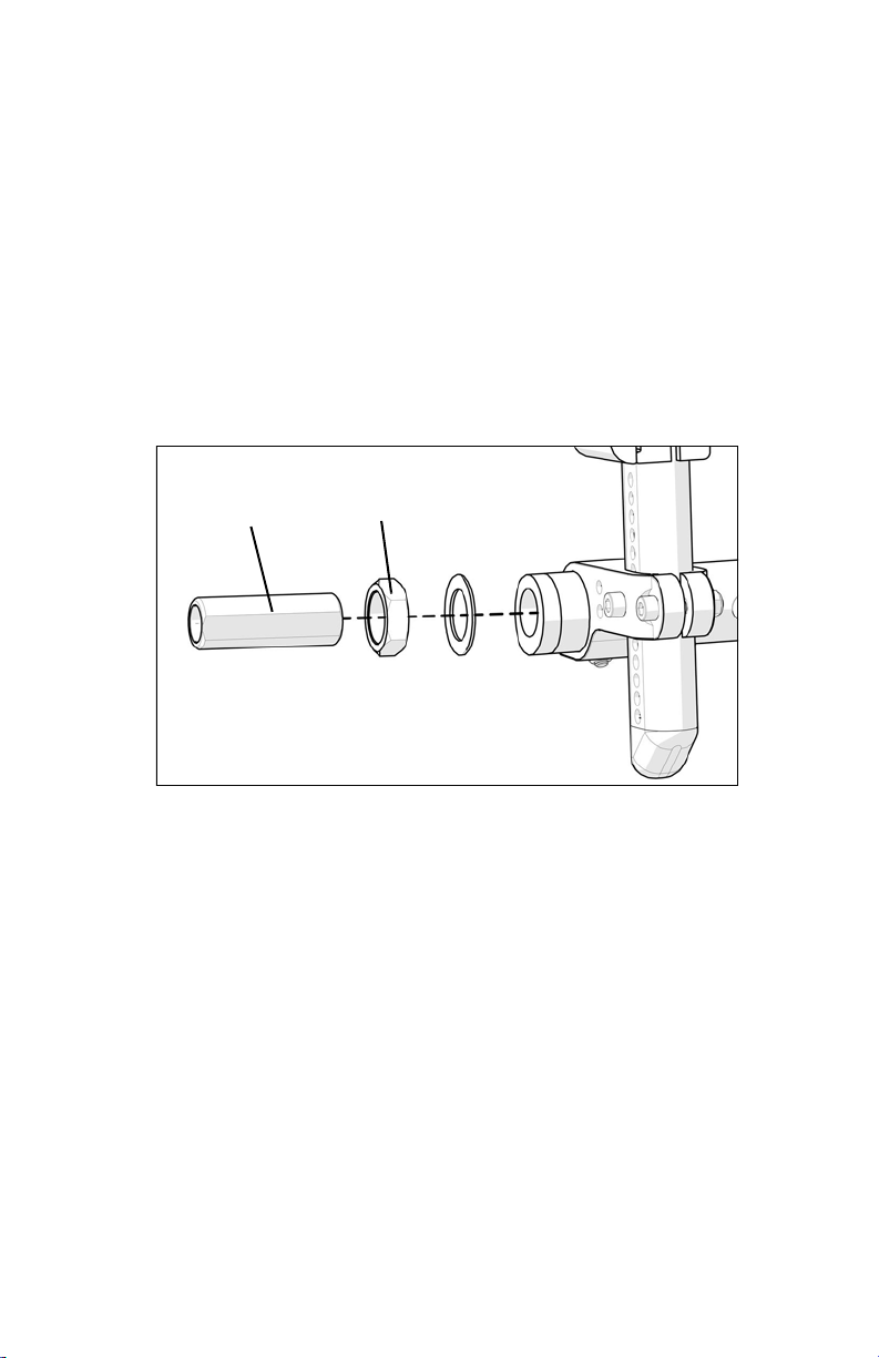
J. Wheelbase Width Adjustment
Adjusting the wheelbase width allows the rider the option to move the wheels closer or further
away from the hips. It also compensates for camber adjustment and gives the proper wheel
spacing to maximize pushing efficiency.
Adjust the wheelbase width:
1. Loosen the nut (Fig. 13:A) with a 24mm wrench and turn the threaded axle sleeve (Fig. 13:B) in
or out to the desired width.
2. Retighten nut.
3. Repeat on opposite side.
24
Page 27
V. SET UP & USE OF YOUR WHEELCHAIR
Fig. 14
C
A
D
E
B
K. Setting Toe to Zero
NOTE: A wheelchair equipped with 0° camber adapter cannot have a toe-in-toe-out condition.
This adjustment is only required when using 2°, 4°, 6° and 8° camber adapters.
Toe refers to how well the rear wheels of the chair are aligned relative to the ground. It affects how
well the chair will roll. Drag or rolling resistance is optimally minimized when the wheel toe is set to
zero.
Setting the toe to zero:
1. Loosen the two cap screws (Fig. 14:A) (1 per side) that secure the camber tube clamp. Then
loosen set screws (Fig. 14:B), 2 per side.
2. Rotate the camber tube (Fig. 14:C) until the screws (Fig. 14:D) that secure the camber
adapters are level with the ground. The toe is now set at zero.
3. Before tightening the screws (Fig. 14:A and B), make certain that the camber tube is centered
left-to-right relative to the wheelchair frame. There should be an equal gap on both sides or
none at all.
4. Tighten one screw to 80 in/lb (Fig. 14:A) then tighten the screw on the opposite side to 80
in/lbs.
5. Tighten set screws (Fig. 14:B) until securely in place.
25
Page 28
V. SET UP & USE OF YOUR WHEELCHAIR
Fig. 15
A
B
A
Fig. 16
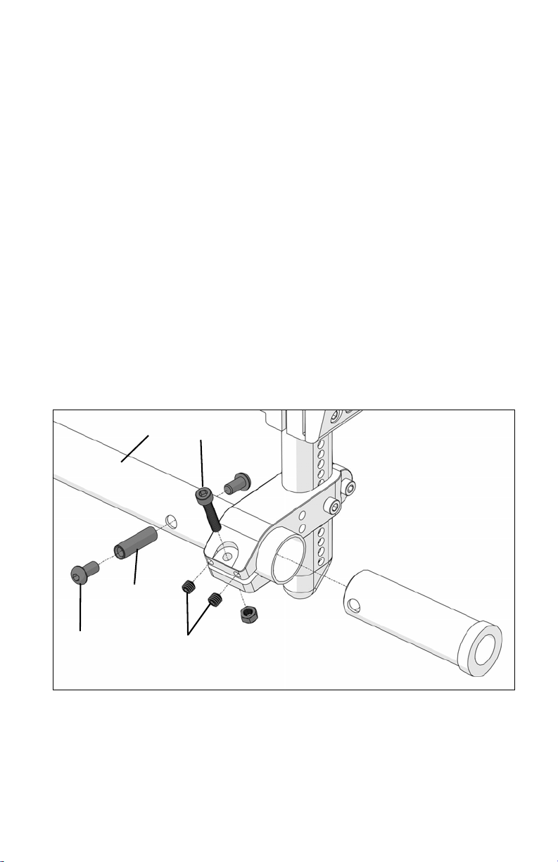
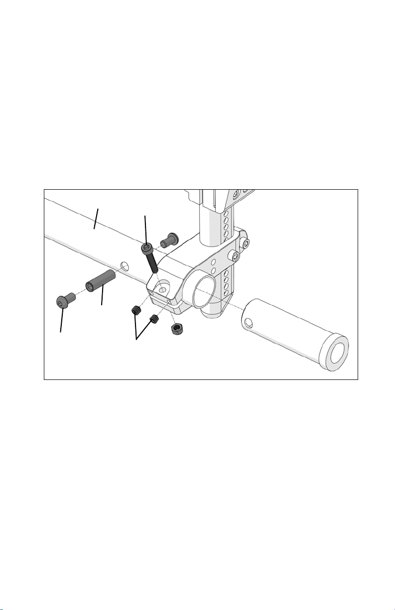
L. Removing the Camber Tube
Removing the Camber Tube on your Clik (Fig. 14)
1. Remove rear wheels.
2. Remove 6mm screw (Fig. 14:D) using two Allen wrenches.
3. Press threaded barrel (Fig. 14:E) through camber tube using Allen wrench.
4. Loosen 6mm screw (Fig. 14:A) to release clamp.
5. Loosen set screws (Fig. 14:B).
6. Slide camber adapter (Fig. 14:G) from end of camber tube (Fig. 14:C).
7. Repeat steps 2 - 6 on other side.
8. If your chair has a Standard or Dynamic 5th wheel, refer to corresponding steps (a - d)
below before moving on to step 9. If your chair does not have a Standard or Dynamic 5th
wheel skip to step 9.
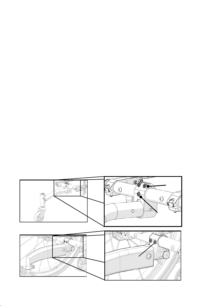
Instructions for removal with STANDARD 5th Wheel (Fig. 15):
a. Remove 5th wheel from receiver and set aside.
b. Remove 5mm bolt from receiver (Fig. 15:A).
c. Loosen two 6mm clamping screws (Fig. 15:B) until receiver slides freely on camber tube.
d. Move to step 9.
Instructions for removal with Dynamic 5th Wheel (Fig. 16):
a. Remove 5th wheel from receiver and set aside.
b. Remove two 6mm bolts from receiver (Fig. 16:A).
c. Receiver can now slide on to the camber tube.
d. Move to step 9.
9. Slide camber tube to left or right to remove from camber tube clamps. If you have a 5th wheel
receiver you need to remove from camber tube at this time.
26
Page 29

V. SET UP & USE OF YOUR WHEELCHAIR
M. Replacing the Camber Tube
To replace the camber tube on your Clik wheelchair:
1. Remove existing camber tube following removal instructions in Section L.
2. Starting on either the left or right side of chair, slide end of new camber tube through camber
clamp. If your chair has a Standard or Dynamic 5th wheel, refer to corresponding steps
below (a - e) before moving on to step 3. If your chair does not have a Standard or
Dynamic 5th wheel skip to step 3.
Instructions for installing STANDARD 5th wheel receiver on camber tube (Refer to Fig. 15 on
previous page):
a. Slide 5th wheel receiver onto end of camber tube that has already been inserted through the
camber tube clamp. Receiver should be below camber tube with notched face towards rear
of chair.
b. Slide camber tube into the opposite side camber clamp.
c. Slide receiver to center of camber tube and align hole in tube and receiver to accept 6mm
bolt.
d. Insert 5mm bolt (Fig. 15:A) into aligned holes. Secure with 5mm nut on back side. Tighten
securely.
e. Tighten 6mm clamping bolts at top of receiver (Fig. 15:B). Move to step 4 on next page.
Instructions for installing Dynamic 5th Wheel receiver on camber tube (Refer to Fig. 16 on
previous page):
a. Slide 5th wheel receiver onto end of camber tube that has already been inserted through the
camber tube clamp. Receiver should be below camber tube with threaded barrel (Fig. 16)
facing front of chair.
b. Slide camber tube into the opposite side camber clamp.
c. Slide receiver to center of camber tube and align two holes in tube and two holes in receiver
to accept 6mm bolts (Fig. 16:A).
d. Insert 6mm bolts (Fig. 16:A) into aligned holes. Secure with 6mm nuts and flat washers on
back side. Tighten securely. Move to step 3.
27
Page 30
V. SET UP & USE OF YOUR WHEELCHAIR
Fig. 17
A
C
E
D
B
M. Replacing the Camber Tube (Continued)
3. Center camber tube in camber clamps.
4. Insert camber adapter into end of camber tube. If using 2°, 4° or 6° camber adapters, rotate
thin wall of threaded end until it is pointing up and through holes align with through holes in
camber tube.
5. Press threaded barrel (Fig. 17:E) into through holes in camber tube.
6. Insert 6mm screw (Fig. 17:D) using two Allen wrenches into threaded barrel and tighten.
7. Repeat steps 3 thru 5 on opposite side of chair.
8. Put rear wheels back onto chair. Refer to Setting Toe to Zero in Section K to ensure wheels are
properly set up and to finish installation of camber tube.
28
Page 31

V. SET UP & USE OF YOUR WHEELCHAIR
Fig. 18
C
A
D
B
D
N. Front Seat Height Adjustments
1. Caster Fork Adjustment
NOTE: By changing the front seat height, the back angle and chair dump are affected. These
should be checked after making this adjustment.
The front seat height can be adjusted in ½" increments by repositioning the caster wheel within
the fork.
a. Using two 4mm hex (Allen) wrenches, turn the button head cap screws (Fig. 18:A) counter-
clockwise until one of the button heads detaches from the internally threaded axle.
b. Remove the remaining cap screw/axle (Fig. 18:B) from the caster assembly. Be sure to
catch the caster spacers (Fig. 18:D) if they fall out.
c. Move the caster (Fig. 18:C) and spacers (Fig. 18:D) to the desired hole in the fork. Reinsert
the cap screw/axle (Fig. 18:B). Reinstall the second button head cap screw (Fig. 18:A) and
tighten to 80 in./lbs.
d. Resquare caster wheels as noted in Section P. Caster Angle Adjustment.
WARNING: Changing the seat height may decrease stability of the chair. Always make
adjustments in small increments and check the stability of your chair with a spotter to prevent a
tip-over. We recommend that you use anti-tip tubes.
DANGER: Failure to heed these warnings may cause serious injury or death.
29
Page 32

V. SET UP & USE OF YOUR WHEELCHAIR
Fig. 19
A
N. Front Seat Height Adjustments (Continued)
2. Caster Housing Height Adjustment
NOTE: By changing the front seat height, the back angle and chair dump are affected. These
should be checked after making this adjustment.
The front seat height can be adjusted in ½" increments by moving the caster housing up or down
on front frame tube.
a. Loosen top two M6 bolts (Fig. 19:A).
b. Start with the left or right caster housing. Move caster housing up or down to achieve
desired front seat height. As you move you should feel the detent click into each dimple of
the frame.
c. Make sure each side is adjusted equally. This can be done by counting the clicks as you
move the caster housing and/or measuring each side after adjusted.
d. Once desired position is achieved retighten M6 bolts (Fig. 19:A).
e. Repeat on opposite side using the same number of clicks.
f. Resquare caster wheels as noted in Section P. - Caster Angle Adjustment.
WARNING: Changing the seat height may decrease stability of the chair. Always make
adjustments in small increments and check the stability of your chair with a spotter to prevent a
tip-over. We recommend that you use anti-tip tubes.
DANGER: Failure to heed these warnings may cause serious injury or death.
30
Page 33

V. SET UP & USE OF YOUR WHEELCHAIR
Fig. 20
A
O. Clik - Rear Seat Height Adjustment
1. Remove your wheels by depressing the buttons on the quick release axle.
2. Use a 3mm Allen wrench and an 8mm open end wrench to remove the two bolts (Fig. 20:A)
holding the upper and lower mounting brackets together.
3. Reposition the mounting brackets to the desired height and replace the two M5 bolts.
4. Repeat on both sides of the wheelchair.
NOTE: Height adjustments are in ¼" increments.
NOTE: A front caster adjustment should be made to correspond with any change in seat angle.
WARNING: Lowering the seat height at the rear of the seat may decrease rearward stability of
the chair. The more you move your rear wheels forward, the more likely your chair will tip over
backwards.
Always make adjustments in small increments and check the stability of your chair with a spotter
to prevent a tip-over. We recommend that you use anti-tip tubes.
DANGER: Failure to heed these warnings may cause serious injury or death.
31
Page 34

V. SET UP & USE OF YOUR WHEELCHAIR
Fig. 21
B
A
Fig. 22
P. Caster Angle Adjustment
To maintain optimal performance of your Clik, the front caster housing should always be aligned
perpendicular to the ground. Your Clik is shipped aligned. Many of the adjustments made in
properly setting up the wheelchair, however, will result in the caster housing getting out of
alignment.
After all other adjustments are made, you should check your caster housing alignment and
realign if the housing is not perpendicular to the ground.
For optimum performance, the caster housing should always be at a 90° angle to the floor
(perpendicular to the ground).
1. To change the angle, place the chair on a flat surface (such as a table).
2. Loosen the two 6mm Allen screws (Fig. 21:A) on top and bottom of caster mount. This will
allow the caster housing to pivot.
3. Place a large right triangle against the table surface and flat trailing edge of caster fork (Fig.
22).
4. To adjust caster angle turn the 3mm adjuster screw (Fig. 21:B). This will adjust caster angle
forward or rearward. This will align the caster stem rotational axis perpendicular to the floor
surface.
5. When the alignment is correct, retighten the two 6mm retaining screws to 80 in./lbs (Fig. 21:A).
6. Tighten screws in a balanced fashion - tighten one screw to 50 in./lbs. and then the second to
50 in./lbs. Return to tighten the first screw to 80 in./lbs. and finally the second screw to 80
in./lbs. Repeat on opposite side.
32
Page 35

V. SET UP & USE OF YOUR WHEELCHAIR
Fig. 23
Axle Sleeve
Axle
Axle Release Button
Fig. 24
Turn
Hold
Q. Wheel Installation & Removal
1. Installing Wheels (Fig. 23)
a. Push in the axle release button on the axle
to allow the locking balls to retract. Make
note of the difference between the
extended and depressed position of the
axle release button and its effect on the
locking balls on the other end of the axle.
b. Insert the axle into the bearing housing on
the wheel if it is separate.
c. Push on quick release button again and
slide axle into axle sleeve.
d. Release the button to lock axle in sleeve. If release button does not fully extend and the
locking balls do not move into the locked position after releasing the button, the axle length
needs to be adjusted.
2. Removing Wheels
a. Hold the wheel close to the hub and push in the button on the outside end of the axle.
b. While still holding the button, pull the wheel and axle out of the axle sleeve.
NOTE: Review and understand Section Q. Wheel Installation & Removal before attempting an
axle adjustment!
3. Adjusting Axles (Fig. 24)
a. To adjust the axle, you will need a 19mm wrench to
turn the adjustment nut. You will also need an 11mm
wrench to securely hold the ball detent end of the axle
to prevent it from turning.
b. If the wheel and axle will not lock into the camber
adapter, the axle requires adjustment. Turn the nut
counter-clockwise approximately ¼ revolution and try
to lock the axle into the camber plug. If it doesn’t lock, continue making small nut adjustments until it securely locks.
c. If the wheel is locked on the chair but there is excessive wheel play (the wheel hub can be
pushed back and forth on the axle), adjust the nut clockwise until there is no perceptible
gap between the wheel and camber tube and the axle is securely locked onto the chair.
DANGER: Make sure the axle push buttons are completely extended and the locking balls on
the inside of the chair are fully engaged before operating the wheelchair. Failure to do so may
result in the wheel falling off and may cause serious injury or death.
33
Page 36

V. SET UP & USE OF YOUR WHEELCHAIR
A
Fig. 25
A
Fig. 26
R. Adjusting the Footrest
Height Adjustment of Footrest:
1. On each side of the frame loosen the 5mm screw
(Fig. 25:A).
2. Once the screw is loosened you may adjust the
footrest tube up or down to the desired height
within the side frame.
3. Try to ensure that both sides are adjusted equally.
4. Retighten the 5mm screw on each side.
Replacing Footrest for Width Adjustment:
NOTE: These instructions do not apply to High Mount footplates. Reference instruction in Section
KK - Clik - High Mount Flip Under Footrest.
1. Loosen the 5mm set screw on each side of the frame (Fig. 25:A).
2. Once the screw is loosened you may remove footrest assembly by sliding downward towards
the floor until upright tubes have been entirely removed from frame.
3. Take new footrest assembly and insert upright tubes into upright front frame tubes.
4. Set desired footrest height.
5. Retighten 5mm screw (Fig. 25:A).
S. Optional Angle Adjustable Footplate
To adjust the angle of the optional angle adjustable footplates:
1. Loosen, but do not remove, the two M6 screws (Fig. 26:A) securing the footplate to the
footplate clamp with a 4mm Allen wrench.
2. Once loose, the footplate will easily rotate around the footrest extension tube.
3. Select the desired position and retighten the two M6 screws to 80 in./lbs.
To change the position of the optional angle adjustable footplates:
1. Remove both M6 screws (Fig. 26:A) from the
footplate. There are M6 nylock nuts recessed on the
underside of the clamp. Be sure to prevent these
from falling as you loosen the screws.
2. Relocate the footplate and insert the screws into the
appropriate holes.
3. Fit the nuts into the slot underneath the clamp and
tighten the screws.
34
Page 37

V. SET UP & USE OF YOUR WHEELCHAIR
Fig. 27
A
Fig. 28
Fig. 29
A
C
B
1°
3°
6°
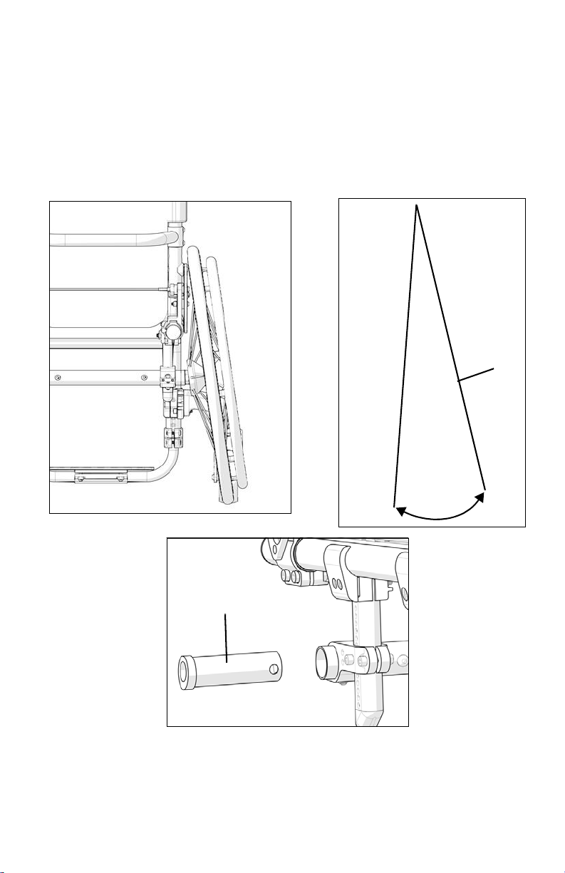
T. Folding Backrest
To fold down the backrest on your Clik wheelchair:
1. Pull the release cable (Fig. 27:A), that is behind the back frame, outward to release the latch.
Fold downward towards the seat frame (Fig. 28).
2. To latch back into place, pull the release cable outward and the back will release and can be
pushed back into the upright position. The backrest will automatically latch onto the side
frame.
3. Ensure a solid engagement onto the latches by pulling back on on the backrest frame into the
upright position.
WARNING: Do not occupy or operate chair when backrest is not latched. This may result in a
fall, tip-over or loss of control causing severe injury to the user or others.
U. Backrest Angle Adjustment
Relax Back Feature:
This chair can be adjusted for a slight recline
upon releasing the back release cable (Fig.
29:A). This is referred to as the "relax back
feature." 1°, 3° and 6° are available.
To adjust, use a 3mm Allen key to
disassemble the backrest stop (Fig. 29:A
and Fig. 29:C) and reassemble in the
desired position on both sides.
35
Page 38

V. SET UP & USE OF YOUR WHEELCHAIR
Fig. 30
A
C
B
U. Backrest Angle Adjustment (Continued)
To adjust the backrest angle:
1. Loosen 6mm screw (Fig. 30:A) on outside of backrest plate. Do this to each side of backrest.
2. Remove 5mm screw (Fig. 30:B) on outside of backrest plate. Do this to each side of backrest.
3. Once desired backrest angle is achieved, realign holes in pivot bracket (Fig. 30:C).
4. Reinsert 5mm screw through locating holes and tighten. Repeat on other side of backrest.
5. Retighten 6mm screw (Fig. 30:A). Repeat on other side of backrest.
NOTE: Lowering backrest height or changing the back angle may decrease rearward stability.
Always make adjustments in small increments and check the stability of your chair with a spotter
to prevent a tip-over.
WARNING: Adjusting the relaxed position or changing the back angle may decrease rearward
stability. Always make adjustments in small increments and check the stability of your chair with a
spotter to prevent a tip-over. Failure to heed these instructions may result in a fall, tip-over or loss
of control causing severe injury to the user or others.
36
Page 39

V. SET UP & USE OF YOUR WHEELCHAIR
Fig. 31
A
B
A
V. Adjusting Backrest Height
To adjust the height of backrest:
1. Remove two 5mm screws from each side of backrest rigidizer bar (Fig. 31:A). (Use of two
3mm Allen wrenches for this adjustment is required.)
2. Using Allen wrench, push the two threaded barrels on each side of backrest rigidizer bar
through screw holes.
3. Grasp upper backrest tube (Fig. 30:B) and move in desired direction of backrest adjustment.
Repeat on opposite side.
4. Once desired height is achieved, realign holes in rigidizer bar, upper and lower backrest tubes.
Repeat on opposite side.
5. Reinsert two threaded barrels into aligned holes on each side. Threaded barrels need to pass
through aligned holes in rigidizer bar, lower and upper backrest tubes in order to secure
backrest into place.
NOTE: Rigidizer bar is height adjustable along lower backrest tube.
6. Reinsert two 5mm screws into threaded barrels (Fig. 31:A) on each side and tighten.
WARNING: Secure backrest to avoid injury or bodily harm.
WARNING: Lowering backrest height may decrease rearward stability. Always make
adjustments in small increments and check the stability of your chair with a spotter to prevent a
tip-over. Failure to heed these instructions may result in a fall, tip-over or loss of control causing
severe injury to the user or others.
37
Page 40

V. SET UP & USE OF YOUR WHEELCHAIR
A
B
Fig. 32
W. Adjusting, Removing and Replacing Backrest
Release Cable for Width Growth
To adjust the length of the backrest release cable:
1. Hold cable end (Fig. 32:B) securely in place.
2. Turn locking pin (Fig. 32:A) clockwise to tighten (shorten) and counterclockwise to loosen
(lengthen) cable. Cable has been adjusted to optimize function when cable is straight from end
to end. Do not overtighten. Locking pin must engage backrest plate pin housing fully on each
side.
3. Adjust evenly on each end of cable.
To remove backrest release cable:
1. Hold cable end (Fig. 32:B) securely in place.
2. Turn locking pin (Fig. 32:A) counterclockwise to unthread cable from pin.
3. Repeat on opposite end of cable.
To replace backrest release cable:
1. Remove existing cable. See instructions above.
2. Align cable end with locking pin (Fig. 32:B).
3. Hold cable end (Fig. 32:B) securely in place while turning locking pin (Fig. 32:A) clockwise to
thread cable into pin. Thread until approximately half of threaded end has been screwed into
locking pin. Repeat on opposite end of cable.
4. Adjust length as needed. See instructions above.
WARNING: Failure to read or comply with these instructions may result in a fall or loss of control
causing severe injury to the user or others.
38
Page 41

V. SET UP & USE OF YOUR WHEELCHAIR
Fig. 33
A
X. Adjusting Backrest Position
To move the location of your Clik backrest:
1. Loosen two 6mm screws on backrest clamp (Fig. 33:A). Repeat on other side.
2. Grasp backrest clamp on each side and slide to desired location. It is important that you move
both sides equally. As adjustment is being made you will feel a clicking in the system. Take
care to move assembly equal distance on each side. Each click is equivalent to ½".
3. Once assembly is in desired location and has clicked into place, tighten the two 6mm screws
on backrest clamp (Fig. 33:A). Repeat on other side.
NOTE: When backrest has been moved, adjustments to COG (Section H), cross tube (Section
JJ) and seat upholstery (Section FF) may be required. Always check rearward stability of the
wheelchair after adjusting and before use.
WARNING: Moving the backrest rearward can decrease rearward stability of the chair. Always
make adjustments in small increments and check the stability of your chair with a spotter to
prevent a tip-over. We recommend that you use anti-tip tubes.
39
Page 42

V. SET UP & USE OF YOUR WHEELCHAIR
Fig. 34
A
B
A
Y. Removing Adjustable Backrest Rigidizer Bar for
Width Adjustment
To remove your adjustable backrest rigidizer bar when growing the width of your Clik:
1. Remove back upholstery by removing Phillips head screw from each side at top of back
upholstery. Slide upholstery off backrest tubes and set aside. Note position of adjustable
rigidizer bar and back tubes for reinstalling after width adjustment.
2. Remove two 5mm screws from each side of adjustable backrest rigidizer bar (Fig. 34:A). (Use
of two 3mm Allen wrenches for this adjustment is required.)
3. Using Allen wrench, push the two threaded barrels on each side of adjustable backrest
rigidizer bar through screw holes.
4. Slide rigidizer bar off backrest tubes. Set aside.
DANGER: Do not use or operate wheelchair when adjustable backrest rigidizer is not installed.
Failure to heed these instructions may result in severe injury or death.
40
Page 43

V. SET UP & USE OF YOUR WHEELCHAIR
Fig. 35
A
A
B
Z. Installing Adjustable Backrest Rigidizer Bar
To install the replacement adjustable height backrest rigidizer bar onto backrest tubes to
complete width adjustment:
1. Slide adjustable rigidizer bar over backrest tubes, upper and lower, to desired location.
2. Relocate adjustable rigidizer bar to desired position.
3. Check upper backrest tubes to ensure they are still set at desired backrest height.
4. Once desired height is achieved realign holes in adjustable rigidizer bar, upper and lower
backrest tubes. Repeat on opposite side.
5. Reinsert two threaded barrels into aligned holes on each side. Threaded barrels need to pass
through aligned holes in adjustable rigidizer bar, lower and upper backrest tubes in order to
secure backrest into place.
NOTE: Rigidizer bar is height adjustable along lower backrest tube.
6. Reinsert two 5mm screws into threaded barrels (Fig. 35:A) on each side and securely tighten.
41
Page 44

Fig. 36
Fig. 37
V. SET UP & USE OF YOUR WHEELCHAIR
AA. Wheel Locks
Clik wheelchairs are shipped with one of several different types of wheel locks preinstalled.
• Push to Lock
• Pull to Lock
• Push to Lock (Flush Mount)
• Short Thro Scissor
• Push to Lock w/Extension Handle
• Pull to Lock w/Extension Handle
• Grade Aids
• Low Profile Scissor Lock
The clamp assembly works the same for all wheel
locks.
a. Using a 5mm Allen wrench, turn one of the
screws in the clamp until it runs easily (less than
one turn).
b. Repeat the same process with the second of
the two screws so the clamp can be adjusted on the frame.
c. Adjust the clamp toward the rear wheel so, when
engaged, the wheel lock compresses the tire and
prevents any wheel movement (Fig. 36).
d. Make sure the wheel lock arms embed in tires at least
1/8 inch when locked. If you fail to do so, the locks
may not work (Fig. 37).
e. Retighten the screws.
NOTE: Always loosen and tighten wheel hardware by
alternating between the two bolts while
loosening/tightening a little at a time. This prevents
overclamping on one set of hardware which can lead to
binding of the fasteners and increased difficulty in removal.
Rear wheel locks are NOT designed to slow or stop a moving wheelchair. Use them only to
keep the rear wheels from rolling when your chair is at a complete stop.
• NEVER use rear wheel locks to try to slow or stop your chair when it is moving.
• To keep the rear wheels from rolling, always set both rear wheel locks when you transfer to
or from your chair.
• Low pressure in a rear tire may cause the wheel lock on that side to slip and may allow the
wheel to turn when you do not expect it.
• Make sure lock arms embed in tires at least 1/8 inch when locked. If you fail to do so, the
locks may not work.
DANGER: Failure to read or comply with these instructions may result in a fall or loss of control
causing severe injury or death to the user or others.
42
Page 45

V. SET UP & USE OF YOUR WHEELCHAIR
BB. Growing Your Clik in Width
It is recommended that you follow the below sequence of adjustments when growing your Clik in
width:
Remove the following assemblies from chair in order listed:
1. Upholstery – (Section EE)
2. Backrest Release Cable – (Section W)
3. Rigidizer Bar – (Section Z)
4. Footrest Assembly – Adjusting the Footrest (Section R) or Clik High Mount Flip Under
Footrest (Section KK). Use section that corresponds with the footrest style found on your
chair.
5. Camber Tube – (Section L)
6. Cross Tube – (Section JJ)
Replace new assemblies for width adjustment in reverse of order listed above. Reference removal
and replacement instructions.
43
Page 46

V. SET UP & USE OF YOUR WHEELCHAIR
Fig. 38
CC. Anti-Tips
Anti-tip tubes help prevent your wheelchair from tipping over backwards. When adjusted properly
they provide a significant increase in rearward stability. Your stability can be affected by traversing
uneven ground, a ramp, slope or other surface that changes your relationship to gravity. Your
stability can also be affected by other forces acting on you and your wheelchair such as someone
pushing down or leaning on your push handles or other parts of your chair. This can happen to
even the most experienced wheelchair user. People in your environment do not necessarily
understand they are impacting your stability.
Ki Mobility strongly recommends the use of Anti-Tip tubes!
WARNING: Anti-tips must be used at all times. Whether traversing uneven ground or sitting in
a crowded room, the unexpected may occur and your weight can dramatically shift causing a fall
which could cause serious injury or death.
1. Installing Anti-Tips (Fig. 38)
a. Press the rear anti-tip release pin on the anti-tip tube so both release pins are drawn inside.
Insert the anti-tip tube into receiver mounted on the camber tube.
b. Insert into the anti-tip tube receiver.
c. Turn the anti-tip tube down until release pin is positioned through the receiver mounting
hole.
d. Insert second anti-tip tube the same way.
44
Page 47

V. SET UP & USE OF YOUR WHEELCHAIR
Fig. 39
Fig. 40
CC. Anti-Tips (Continued)
2. Adjusting Height of Wheel Extension (Fig. 39)
The anti-tip tube wheels may have to be raised or lowered to
achieve proper clearance of 1½" to 2".
a. Press the anti-tip wheel release pin so the release pin is
drawn inside.
b. Raise or lower to any of the predrilled holes.
c. Release pin.
d. Adjust the second anti-tip tube wheel the same way.
Both wheels should be at exactly the same height.
3. Turning Anti-Tip Tubes Up (Fig. 40)
Turn anti-tip tubes up when being pushed by an
attendant, overcoming obstacles or climbing curbs.
a. Press the rear anti-tip tube release pin.
b. Hold pin in and turn anti-tip tube up.
c. Release pin.
d. Repeat with second anti-tip tube.
e. Remember to return anti-tip tubes to down posi-
tion after completing maneuver.
DANGER: Failure to read and heed these instructions may result in damage to your wheelchair,
a fall or loss of control causing severe injury to the user or others.
45
Page 48

V. SET UP & USE OF YOUR WHEELCHAIR
DD. Cushion Installation
a. The Clik was designed to be used with a proper wheelchair cushion.
DANGER: Sitting for long periods of time without a proper wheelchair cushion can cause
pressure ulcers which can be serious in nature and result in death.
b. The standard sling upholstery or seat pan is provided with loop Velcro type fastener strips.
The cushion being used should have hook Velcro type fasteners that can engage the loop of
the seat sling to keep the cushion from sliding out from under you. Make sure the cushion is
securely attached before transferring or sitting in the wheelchair.
c. A standard seat sling may not have been provided with your chair. Check with your wheel-
chair provider if an aftermarket replacement to the original equipment sling has been provided. If so, make sure you follow the instructions for use provided by the aftermarket
manufacturer.
d. Before every use, always check to be sure the cushion is securely adhered to the hook and
loop on the seat sling to avoid cushion slipping or moving unexpectedly. If cushion is not
properly attached to the seat sling, it could slide backwards into the backrest release cable
causing the backrest to release and fold and/or move unexpectedly.
DANGER: Failure to properly secure a cushion can cause it to slide out during use or transfers
and could result in a fall or loss of control and cause severe injury or death.
EE. Upholstery Fabric
1. You must immediately replace seat and back upholstery that has worn through and shows
signs of failing. If you fail to do so, the seat or back may fail.
2. The seat sling material will weaken over time. Look for fraying, thin spots, or stretching of
fabrics especially at edges and seams. This should be done weekly.
3. The repeated action of transferring to your wheelchair will weaken sling material and result
in the need to inspect and replace the seat more often.
4. Be aware that laundering or excess moisture will reduce flame retardation of the fabric.
5. Contact your wheelchair provider if you have concerns about your seat or back, or feel it
needs to be replaced.
WARNING: Failure to comply with these instructions may result in damage to your wheelchair, a
fall or loss of control causing severe injury to the user or others.
46
Page 49

V. SET UP & USE OF YOUR WHEELCHAIR
Fig. 41
A
B
FF. Adjusting and/or Growing Your Seat Upholstery
1. Depth Adjustment
Your Clik seat upholstery can grow in depth by 2".
a. Lift rear flap of front seat upholstery piece from rear section of seat upholstery.
b. Reach under chair and pull down on front of rear upholstery, detaching flap from the front
seat upholstery section.
c. Remove Phillips head screws from rear upholstery section on each side of frame (Fig. 41:A).
d. Grab seat upholstery on each side and slide rear upholstery section towards rear of chair
until screw holes and seat upholstery slots align (Fig. 41:B).
e. Reinsert and tighten Phillips head screws (Fig. 41:A).
2. Seat Upholstery Tension Adjustment
a. Reach under seat upholstery to find the tension adjustable hook and loop flap. This should
be located on bottom right side of seat upholstery.
b. Loosen Phillips head screws on same side of seat upholstery as tension adjustable flap (Fig.
41:A).
c. Separate hook from loop on tension adjustable flap by pulling apart.
d. To tighten seat upholstery, pull tension adjustable flap towards opposite side of chair. To
loosen seat upholstery, apply pressure from top of seat upholstery towards ground.
e. When seat upholstery has reached desired level of tension, press hook and loop back
together.
f. Retighten Phillips head screws (Fig. 41:A).
47
Page 50

V. SET UP & USE OF YOUR WHEELCHAIR
Fig. 42
FF. Adjusting and/or Growing Seat Upholstery (Continued)
3. Seat upholstery replacement (Fig. 42)
a. Remove 5mm Phillips head screws from seat rails on each side of frame and set aside.
b. Remove seat upholstery from seat rails.
c. Slide new seat upholstery onto seat rails.
d. Line up holes in seat rails with threaded inserts in frame.
e. Replace 5mm Phillips head screws by partially threading into place. Once all screws have
been started, go back and tighten to secure.
48
Page 51

V. SET UP & USE OF YOUR WHEELCHAIR
Fig. 43
A
B
Fig. 44
A
GG. Clik - Standard 5th Wheel (Optional)
Ki Mobility recommends anti-tip tubes or Standard 5th wheel for all wheelchairs.
Inserting and removing the standard 5th wheel
a. Press the two release buttons (Fig. 43:A) on the support tube so that both buttons are
drawn inside.
b. Insert into the support tube receiver (Fig. 43:B).
c. Rotate the support tube down until release pin buttons are positioned through the receiver
mounting holes.
Adjusting the position from the floor
a. The caster housing is adjustable within the support tube.
b. Remove wing nut (Fig. 44:A) from bolt holding caster housing into the support tube.
c. Slide housing to desired height and replace bolt and secure wing nut.
If the caster touches the ground, it is possible that the large rear wheels might not touch the
ground. Ki Mobility recommends setting the Standard 5th wheel at least ½" above the ground.
Consider a higher position if the wheelchair is being used outdoors.
49
Page 52

V. SET UP & USE OF YOUR WHEELCHAIR
Fig. 45
A
D
C
B
Fig. 46
A
B
HH. Clik - Dynamic 5th Wheel (Optional)
Ki Mobility recommends anti-tip tubes or Rotating 5th wheel for all wheelchairs.
1. Inserting and removing the Dynamic 5th wheel
a. To remove, pull the release knob (Fig. 45:A) to disengage the locking pin and slide assembly
out of the tubular receiver (Fig. 45:B).
b. To insert assembly, pull release knob (Fig. 45:A) and insert assembly into tubular receiver
(Fig. 45:B).
c. Rotate the assembly in receiver to align slot (Fig. 45:C) and cross pin (Fig. 45:D).
d. Release knob (Fig. 45:A).
2. Adjusting the position from the floor
a. The caster stem is adjustable within the Dynamic 5th wheel arm.
b. Loosen 6mm bolt in clamping ring (Fig. 46:A).
c. Grasp caster fork assembly and move up or down to desired position (Fig. 46:B). Take care
to not rotate caster stern within housing while repositioning.
d. Retighten 6mm bolt in clamping ring (Fig. 46:A).
50
Page 53

V. SET UP & USE OF YOUR WHEELCHAIR
Fig. 47
A
Fig. 48
A
B
A
C
D
HH. Clik - Dynamic 5th Wheel (Optional)
3. Adjusting spring force
a. Remove Dynamic 5th wheel assembly from chair. Refer to Section HH, Instruction set 1.
b. Loosen 6mm screw located on the underside of assembly (Fig. 47:A).
c. To decrease spring rate, slide screw and elastomer away from caster fork assembly. To
increase spring rate, slide screw and elastomer towards caster fork assembly.
d. Retighten 6mm screw (Fig. 47:A). Take care to not overtighten.
4. Changing or replacing elastomer
Your Clik has been provided with two elastomers for the Dynamic 5th Wheel. The harder one is
black and the softer one is yellow.
a. Remove dynamic 5th wheel assembly from chair. Refer to Section HH, Instruction set 1.
b. Remove 6mm screw from side of Dynamic 5th Wheel arm (Fig. 48:A). (Two 4mm Allen
wrenches are needed for this step)
c. Using Allen wrench, push threaded barrel (Fig. 48:B) out of arm assembly.
d. Slide tubular receiver (Fig. 48:C) out of assembly.
e. Remove 6mm screw located on the underside of assembly. This will release the elastomer
(Fig. 48:D). Remove elastomer and set aside.
f. Insert elastomer into opening on arm assembly with threaded insert facing down towards
slot, aligned with slot in arm.
g. Thread 6mm screw and washer (Fig. 48:D) through slot and into threaded insert in elasto-
mer.
h. Retighten 6mm screw (Fig. 48:D). Take care to not overtighten.
i. Reinsert tubular receiver (Fig. 48:C) into arm. Take care to place flat arm of tubular receiver
over the top of elastomer.
j. Align holes on arm and tubular receiver to insert threaded barrel (Fig. 48:B) and 6mm screw
(Fig. 48:A).
k. Tighten 6mm screws (Fig. 48:A). (Two 4mm Allen wrenches are needed for this step)
51
Page 54

V. SET UP & USE OF YOUR WHEELCHAIR
Fig. 49
A
C
B
II. Adjusting Cross Tube and Armrest/Sideguard
Position on Frame
To Adjust Cross Tube Position on Frame:
1. Remove wheels, side guards and armrests from chair in order to allow easier access to cross
tube.
2. If your Clik has sideguards, Pediatric T-arm will have a receiver built into the cross tube
assembly (Fig. 49:C).
3. Loosen four 6mm screws on each side of cross tube clamp (Fig. 49:A). Loosen screws only
until the clamp moves freely alongside the frame without falling off.
4. Grab both sides of clamp assembly and slide in direction of desired location. It is important
that you move both sides equally. As adjustment is being made you will feel a clicking in the
system. Take care to move assembly equal distance on each side. Each click is equivalent to
½".
5. Once assembly is in desired location and has clicked into a dimple in the frame, retighten the
four 6mm screws (Fig. 49:A) on each side.
JJ. Replacing Cross Tube for Width Adjustment
To Replace Cross Tube When Growing Your Clik:
1. Remove wheels, side guards and armrests from chair in order to allow easier access to cross
tube.
2. Remove two 6mm flat head screws (Fig. 49:B) from each side of cross tube clamp assembly.
3. Slide cross tube out of clamp assembly. Set aside.
4. Grab new cross tube on each side and slide straight into clamp assembly. Note that the
assembly has a very tight fit. You may need to apply pressure from inside frame outward to
allow clearance when sliding cross tube into clamp assembly.
5. Align holes in cross tube with holes in clamp.
6. Replace two 6mm (Fig. 49:B) flat head screws on each side. Retighten screws on each side
securely.
52
Page 55

V. SET UP & USE OF YOUR WHEELCHAIR
Fig. 50
A
B
KK. Clik - High Mount Flip Under Footrest (Optional)
To adjust the angle of the footplates:
a. Loosen, but do not remove, the two 6mm flat head screws on center clamp.
b. Once loose, the clamp will rotate around the footrest extension tube.
c. Select desired position and retighten the two 6mm flat head screws to 80 in./lbs.
To change the position of the optional angle adjustable footplates:
a. Remove both M6 screws (Fig. 50:A) from the footplate. There are M6 nylock nuts recessed
on the underside of the clamp. Be sure to prevent these from falling as you loosen the
screws.
b. Relocate the footplate and insert the screws into the appropriate holes.
c. Fit the nuts into the slot underneath the clamp and tighten the screws.
To change the height of the footplate on frame:
a. Slightly loosen both 6mm screws (Fig. 50:B) from the footplate clamp. Keep the clamp snug
so that the assembly holds together. Repeat on other side of the wheelchair.
b. The entire footplate assembly will slide up and down on the frame.
c. After locating desired position, tighten one 6mm screw (Fig. 50:B) slightly on each side.
Once secure finish tightening the four 6mm screws (Fig. 50:B). Turn each screw a little at a
time to prevent the clamp from clamping down unevenly.
NOTE: Tightening the screws unevenly may result in damage to the threads inside the clamp.
53
Page 56

V. SET UP & USE OF YOUR WHEELCHAIR
Fig. 51
A
B
E
C
D
Fig. 52
A
KK. Clik - High Mount Flip Under Footrest (Optional)
Removal and replacement of footplate assembly for width growth:
1. Removal (Fig. 51)
a. Remove two 6mm screws (Fig. 51:A) from each side of footrest frame clamp.
b. The entire footplate assembly can now be removed.
2. Replacement (Fig. 51)
a. Loosen two 6mm flat head screws (Fig. 51:B) on center clamp.
b. Slide tube (Fig. 51:C) out of center clamp.
c. Remove 6mm screw (Fig. 51:D) from mount bracket.
d. Slide tube (Fig. 51:C) out of mount bracket.
e. Replace tube (Fig. 51:C) with one of the new tubes from growth kit.
f. Repeat steps A - E on opposite side.
g. Reinsert 6mm screw (Fig. 51:D) through mount bracket and tube (Fig. 51:C). Retighten and
repeat on opposite side. Take care to use same hole placement in mount bracket on both
sides.
NOTE: There are three possible positions (Fig. 52:A). Choose position that is optimal for
desired footrest height.
h. Insert tube (Fig. 51:C) through pivot bracket (Fig. 51:E) and into center clamp. Repeat on
opposite side.
i. Mount complete footrest assembly onto front frame in desired footrest height location by
placing clamps on front frame.
j. Replace two 6mm screws (Fig. 51:A) into clamp on each side.
k. Tighten one 6mm screw slightly on each side. Once secure, finish tightening the four 6mm
screws. Turn each screw a little at a time to prevent the clamp from clamping down
unevenly.
l. To set footplate angle, rotate center clamp around the footrest extension tube.
m. Select desired position and retighten the two 6mm flat head screws (Fig. 51:B) to 80 in./lbs.
54
Page 57

VI. MAINTENANCE
A. Inspecting Your Wheelchair
Regular and routine maintenance will extend the life of your wheelchair while improving it’s
performance. Wheelchair repairs and the replacement of parts should be done by a qualified
technician or an authorized Ki Mobility Supplier.
1. General Inspections
a. Clean your chair at least once per month. You may need to clean your chair more frequently
if you operate it in dirty environments, such as a work site.
b. Check to be sure that all fasteners are tight. Unless otherwise noted, fasteners should be
tightened to 40 in./lbs.
c. Check Tires and Casters:
• Check the tire for tread wear. Replace the tires if the tread is worn off or has flat spots or
visible cracks.
• If you have inflatable tires with a valve stem, check the pressure and set to the pressure
listed on the tire sidewall.
DANGER: Replace worn tires. The wheel locks will not grip properly if you fail to maintain the air
pressure shown on tire sidewall. This could result in a fall or loss of control and cause severe injury
or death.
d. Check spoke wheels for loose spokes.
e. Check your wheel locks. As tires wear, the wheel locks should be adjusted. See Section AA
- Wheel Locks.
f. Check your upholstery for tears or sagging. Your upholstery is designed to be tightened
because it will stretch over time. See Section FF - Adjusting and/or Growing Your Seat
Upholstery.
55
Page 58

VI. MAINTENANCE
A. Inspecting Your Wheelchair (Continued)
Weekly
a. Check wheel locks to be sure they are adjusted correctly.
b. Check axle sleeves to ensure the axle sleeve nuts are tight.
c. Check for broken, bent or loose spokes.
d. Check that casters can spin freely.
e. Inspect tires and casters for wear spots.
f. Check pneumatic tires for proper inflation.
Monthly
a. Inspect rear wheel axles and tighten if necessary.
b. Inspect caster housing bearings for hair build up and remove if necessary.
c. Inspect wheel locks to be sure assembly is tight. Ensure wheel locks properly engage the
tires.
d. Check that all fasteners are tight and secure.
e. Inspect hand grips to ensure they are not loose.
f. Inspect frame for any deformities, defects, cracks or bends. These could be signs of fatigue
in the frame which could result in a failure of the chair. Discontinue use of the wheelchair
immediately and contact your authorized Ki Mobility dealer.
Annually
a. Have wheelchair checked and adjusted by a qualified technician.
DANGER: Do not continue to use wheelchair with broken or worn components. This could
result in a fall or loss of control and cause severe injury or death.
WARNING: After adjustments and before using this wheelchair, ensure all of the fasteners are
tight and secure or injury or damage may occur.
CAUTION: Do not overtighten fasteners as this could damage the frame tubing.
DANGER: Failure to read and comply with these instructions may result in a fall or loss of control
causing severe injury or death to the user or others.
56
Page 59

VI. MAINTENANCE
B. Cleaning Your Clik Wheelchair
1. Axles and wheels
a. Clean around the axles and wheels WEEKLY with a damp rag.
b. Hair and lint will lodge in the caster housing. Disassemble the caster housing every six
months to remove entangled hair.
NOTE: Do not use WD-40 or any other penetrating oil on this wheelchair. This will destroy the
sealed bearings.
NOTE: Do not use any chemical cleaning agents on casters or tires.
2. Upholstery
a. Hand-wash only (machine washing can cause damage to the fabric).
b. Line dry only. DO NOT machine dry; heat from the dryer will damage fabric.
WARNING: Failure to read and comply with these instructions may result in damage to your
wheelchair, a fall or loss of control causing severe injury to the user or others.
C. Storage
a. When not in use, keep your chair in a clean, dry area. Failure to do so may result in your
chair rusting and/or corroding.
b. If your chair has been in storage for more than a few weeks, you should make sure it is
working properly. You should inspect and service, if necessary, all items in Section VI. A.
Inspecting your Wheelchair.
c. If your chair has been in storage for more than two months, it should be serviced and
inspected by your authorized supplier before you use it.
WARNING: Failure to read and comply with these instructions may result in damage to your
wheelchair, a fall or loss of control causing severe injury to the user or others.
57
Page 60

VII. WARRANTY
Ki Mobility warrants the frame and quick-release axles of this wheelchair against defects in
materials and workmanship for the life of the original purchaser. All other Ki Mobility-made parts
and components of this wheelchair are warranted against defects in materials and workmanship
for one year from the date of first consumer purchase.
The expected life of the frame is five years.
Limitations to the Warranty
1. We do not warrant:
a. Wear items: Upholstery, tires, armrest pads, tubes, armrests and push-handle grips.
b. Damage resulting from neglect, misuse or from improper installation or repair.
c. Damage from exceeding weight limit.
2. This warranty is VOID if the original chair serial number tag is removed or altered.
3. This warranty is VOID if the original chair has been modified from its original condition and it is
determined the modification resulted in failure.
4. This warranty applies in the USA only. Check with your supplier to find out if international
warranties apply.
Ki Mobility’s Responsibility
Ki Mobility’s only liability is to replace or repair, at our discretion, the covered parts. There are no
other remedies, expressed or implied.
Your Responsibility
a. Notify Ki Mobility, via an authorized supplier, prior to the end of the warranty period and get
a return authorization (RA) for the return or repair of the covered parts.
b. Have the supplier send the authorized return, freight pre-paid, to:
Ki Mobility
5201 Woodward Drive
Stevens Point, WI 54481
c. Pay any charges for labor to repair or install parts.
58
Page 61

Page 62

I. INTRODUCCIÓN
Gracias por comprar una silla de ruedas Little Wave “Clik”
o Little Wave Clik XPe!
Por favor, no use esta silla de ruedas sin antes leer completamente este manual.
ANTES de conducir, debe estar capacitado en el uso seguro de esta silla por un
practicante de Tecnología Asistencial (ATP) o profesional clínico.
Si usted tiene alguna pregunta o inquietud acerca de cualquier aspecto de esta silla de
ruedas, en este manual, o el servicio prestado por Ki Mobility o su proveedor minorista,
por favor no dude en ponerse en contacto con nosotros por teléfono al:
715-254-0991
Por escrito a:
Ki Mobility
5201 Woodward Drive
Stevens Point, WI 54481
U.S.A
O por correo electrónico a:
sales@kimobility.com
O a través de nuestro Representante EU Autorizado:
James Leckey Design
19C Ballinderry Road
Lisburn
BT28 2SA
Phone: 0800 318265 (UK) or 1800 626020 (ROI)
www.leckey.com
60
Page 63

II. TABLA DE CONTENIDOS
I. INTRODUCCIÓN
II. TABLA DE CONTENIDOS
III. AVISO - LEA ANTES DE USAR
A. Su Seguridad y Estabilidad.................................................................. 63
IV. ADVERTENCIAS
A. Palabras Indicadoras........................................................................... 63
B. Advertencias Generales....................................................................... 64
C. Cinturones de Posicionamiento........................................................... 65
D. Andando Su Silla de Ruedas............................................................... 66
E. Controles Motorizados ........................................................................ 67
F. Ascendiendo Escaleras....................................................................... 67
G. Descendiendo Escaleras..................................................................... 67
H. Transferencias..................................................................................... 68
I. Su Silla de Ruedas y el Medio Ambiente ............................................. 68
J. Modificando su Silla de Ruedas .......................................................... 69
K. Estabilidad de la Silla de Ruedas......................................................... 69
V. CONFIGURACIÓN Y USO
A. Su Little Wave Clik & Sus Partes ......................................................... 72
B. Uso Tránsito........................................................................................ 73
C. Brazos T con Altura Ajustable ............................................................. 76
D. Apoyabrazos Ajustables, Acolchados, Swing Away............................. 77
E. Ajuste del Brazo T Pediátrico .............................................................. 78
F. Apoyabrazos Extendido Flip Up con Angulo Ajustable Bloqueable ...... 78
G. Advertencias de Apoyabrazos............................................................. 79
H. Ajuste del Centro de Gravedad ........................................................... 79
I. Camber de Rueda............................................................................... 81
J. Ajuste del Ancho de la Base de Ruedas.............................................. 82
K. Seteando la Orientación de la Rueda Posterior a Cero ........................ 83
L. Removiendo el Tubo Camber.............................................................. 84
M. Reemplazando el Tubo Camber.......................................................... 85
N. Ajustes de Altura de Asiento Anterior .................................................. 87
O. Clik - Ajuste de Altura de Asiento Posterior ......................................... 89
P. Ajuste de Angulo de Rueda Pivotante ................................................. 90
Q. Instalación & Remoción de Ruedas..................................................... 91
R. Adjustando el Apoyapies..................................................................... 92
S. Apoyapies con Angulo Ajustable Opcional .......................................... 92
T. Espaldar Plegable ............................................................................... 93
U. Ajuste de Angulo de Espaldar ............................................................. 93
V. Ajustando la Altura del Espaldar .......................................................... 95
W. Ajustando, Removiendo y Reemplazando el Cable de Liberación de
Espaldar para Crecimiento.................................................................. 96
61
Page 64

II. TABLA DE CONTENIDOS
X. Ajustando la Posición del Espaldar...................................................... 97
Y. Removiendo la Barra Estabilizadora Ajustable del Espaldar para Ajustar el
Ancho................................................................................................. 98
Z. Instalando la Barra Estabilizadora Ajustable del Espaldar..................... 99
AA. Frenos de Ruedas..............................................................................100
AB. Creciendo su Clik en Ancho ...............................................................101
BB. Anti-Vuelcos.......................................................................................102
CC. Instalación del Cojín ...........................................................................104
DD. Tela del Tapizado ...............................................................................104
EE. Ajustando y/o Creciendo su Tapizado de Asiento ..............................105
FF. Clik - 5ta. Rueda Estándar (Opcional).................................................107
GG. Clik - 5ta. Rueda Dinámica (Opcional) ................................................108
HH. Ajustando Cruceta y Posición de Apoyabrazos/Protector Lateral en el
Cuadro ..............................................................................................110
II. Re-instalando la Cruceta por Ajuste de Ancho ...................................110
JJ. Clik - Apoyapies de Montaje Alto Flip Under (Opcional) ......................111
VI. MANTENIMIENTO
A. Inspeccionando su Silla de Ruedas....................................................113
B. Limpiando su Silla de Ruedas Clik......................................................115
C. Almacenamiento ................................................................................115
VII. GARANTÍA ..................................................................................................116
62
Page 65

III. AVISO - LEA ANTES DE USAR
A. Su Seguridad y Estabilidad
Ki Mobility fabrica muchas y diferentes sillas de ruedas que pueden satisfacer sus
necesidades. Usted debería consultar a un Asistente Técnico Profesional al seleccionar el
modelo que mejor cubra sus requerimientos particulares, quien podrá indicarle cómo setear y
ajustar su silla de ruedas. La elección final de las opciones de sillas de ruedas y sus ajustes,
son suyas y de su profesional médico. Las opciones que usted puede elegir y los ajustes de
seteo de la silla de ruedas tienen un impacto directo sobre su estabilidad. Los factores a
considerar que afectan su seguridad y estabilidad son:
a. Sus habilidades y capacidades personales, incluyendo fuerza, balance y coordinación.
b. Los tipos de dificultades y obstáculos que usted puede encontrar a lo largo del día.
c. Las dimensiones, opciones y seteos específicos. En particular, la altura de la silla, el
ángulo del asiento, el ángulo del espaldar, tamaño y posición de las ruedas posteriores
y el tamaño y posición de las ruedas pivotantes anteriores. Cualquier modificación a
alguno de estos ítems, cambiará la estabilidad de su silla de ruedas. Usted sólo
debería realizar estas modificaciones luego deconsultar a un profesional calificado.
IV. ADVERTENCIAS
A. Palabras Indicadoras
En este manual usted encontrará palabras "Indicadoras". Estas palabras son utilizadas para
identificar y convenir la gravedad de los diversos peligors. Antes de utilizar esta silla, usted y
cada una de las personas que podrían asistirlo, deberían leer este manual en su totalidad. Por
favor note las palabras "Indicadoras" y considere cualquier advertencia, alerta o peligro.
Asegúrese de seguir todas las instrucciones y utilizar su silla de forma segura. La palabra
indicadora se refiere a los peligros o prácticas no seguras que pueden causar daños severos
o la muerte, a usted o a otras personas. Las "Advertencias" incluyen tres categorías
principales, que son:
PELIGRO – Peligro indica una situación peligrosa inminente que, de no ser evitada, puede
resultar en lesiones severas o muerte.
ADVERTENCIA – Advertencia indica una situación potencialmente peligrosa que, de no ser
evitada, podría resultar en lesiones severas o la muerte.
PRECAUCION – Precaución indica una situación potencialmente peligrosa que, de no ser evitada, podría resultar en lesiones o daños a usted o su silla de ruedas.
Estas palabras "señal" serán colocadas a lo largo del manual, donde sea apropiado, para
señalar las situaciones peligrosas. Ver la siguiente lista de situaciones peligrosas que se
aplican al uso general de esta silla de ruedas.
63
Page 66

IV. ADVERTENCIAS
B. Advertencias Generales
ADVERTENCIA: No exceda el límite de peso de 165 libras (75kg) para la Little Wave Clik. Este
es el peso combinado del usuario y de todos los ítems que lleva consigo. Exceder el límite de
peso puede causar daños a su silla o incrementar la posibilidad de caída o vuelco hacia atrás,
resultando en lesiones severas o muerte, tanto al usuario como a terceros.
PELIGRO: No utilice esta silla para entrenamiento de peso. El movimiento de peso adicional
puede alterar el centro de gravedad de la silla de ruedas, aumentando la posibilidad de un vuelco
hacia adelante que puede causar daños a su silla o lesiones severas o muerte, al usuario o a
terceros.
ADVERTENCIA: Si su silla de ruedas está equipada con llantas inflables, asegúrese de que
las llantas han sido infladas a la presión correcta como se indica al costado de la misma. Su
proveedor de sillas de ruedas puede determinar si las llantas están bien infladas. Utilizar su silla de
ruedas sin inflar adecuadamente las llantas puede tener un efecto en la estabilidad de la silla,
haciendo que ésta vuelque hacia adelante, provocando lesiones o muerte del usuario o terceros.
PELIGRO: No intente empujar su silla de ruedas hacia arriba/abajo de rampas con una
inclinación mayor a 9 grados. Esto es peligroso e incrementa la posibilidad de una caída o vuelco
hacia atrás, resultando en lesiones severas o la muerte del usuario o terceros.
ADVERTENCIA: No intente empujar su silla de ruedas en una elevación resbaladiza o
cubierta de hielo, aceite o agua. Esto puede causar una situación inestable y resultar en muerte
o lesiones severas al usuario o a terceros.
ADVERTENCIA: No se incline sobre el costado o el espaldar de la silla para extender su
alcance. Esto puede causar una caída fuera de la silla o que la misma se vuelque, resultando en
lesiones o muerte.
PELIGRO: No intente levantar la silla sosteniéndola de partes removibles tales como los
apoyabrazos o apoyapiés. Sólo levante la silla sosteniéndola del cuadro. Esto podría causar
caídas o falta de control y resultar en lesiones severas o muerte.
PRECAUCION: No ajuste demasiado las tuercas y hardware que sostienen los varios
componentes unidos al cuadro. Esto podría causar serios daños y afectar la seguridad y
durabilidad de la silla de ruedas.
64
Page 67

IV. ADVERTENCIAS
C. Cinturones de Posicionamiento
Los cinturones de posicionamiento están diseñados para asistir en el apropiado
posicionamiento dentro de la silla de ruedas. No están diseñados como cinturones de
seguridad. Utilice los cinturones de posicionamiento SOLO para ayudar a sostener la postura
del usuario. El uso inadecuado de los cinturones de posicionamiento puede causar lesiones
severas o muerte del usuario.
• Asegúrese de que el usuario no se desliza por debajo del cinturón de posicionamiento
en el asiento de la silla. Si esto ocurre, la respiración del usuario podría estar
comprometida, causando muerte o lesiones severas.
• El cinturón de posicionamiento debería tener un ajuste adecuado, lo suficientemente
apretado para sostener la posición pero no tan apretado que impida la respiración.
Usted debería poder deslizar su mano entre el cinturón de posicionamiento y el
usuario.
• NUNCA Utilice el Cinturón de Posicionamiento:
a. Como un restrictor. Un restrictor requiere orden médica.
b. En un usuario que se halla inconsciente.
c. Como un restrictor del ocupante de un vehículo de motor. Un cinturón de posiciona-
miento no está diseñado para reemplazar al cinturón de seguridad, que se halla en el
cuadro del vehículo. Durante una frenada sorpresiva, con la fuerza de la misma, el
usuario podría ser lanzado hacia adelante. Los cinturones de seguridad de la silla de
ruedas no evitarán esto y otras lesiones podrían resultar del uso de cinturones o correas.
PELIGRO: El no cumplimiento de las instrucciones mencionadas podría resultar en lesiones
severas o muerte.
65
Page 68

IV. ADVERTENCIAS
D. Andando Su Silla de Ruedas
ADVERTENCIA: No empuje su silla en terrenos arenosos, desprendidos o rugosos. Esto
podría causar una pérdida en la estabilidad y resultar en caída o pérdida de control y causar
lesiones severas o muerte.
PELIGRO: En la mayoría de los estados, no es legal utilizar sillas de ruedas en caminos
públicos. Si usted se ve obligado a utilizar un camino público, esté alerta al peligro de
vehículos de motor. El uso de la silla de ruedas en caminos públicos puede causar lesiones
severas o muerte.
ADVERTENCIA: Los obstáculos y los peligros del camino (tales como huecos y aceras
dañadas) pueden dañar su silla y causar caída, vuelco hacia adelante o pérdida de control. El
no cumplir con estas instrucciones puede resultar en lesiones severas o la muerte.
PELIGRO: No utilice su silla de ruedas en una escalera. Utilizar la silla en una escalera puede
causar lesiones severas o muerte.
Para minimizar estos riesgos:
1) Manténgase alerta para verificar el área frente a su silla mientras la conduce.
2) Asegúrese de que los pisos donde usted vive y trabaja están nivelados y libres de
obstáculos.
3) Retire o cubra los dinteles de las puertas entre habitaciones.
4) Instale una rampa en la puerta de entrada o salida. Asegúrese que no haya caídas al
final de la rampa.
5) Para corregir su centro de balance:
a. Incline la parte superior de su cuerpo levemente hacia ADELANTE mientras
pasa un obstáculo.
b. Presione la parte superior de su cuerpo HACIA ATRÁS cuando pase de un
nivel alto a uno bajo.
6) Si su silla posee tubos anti-vuelcos, trábelos en su lugar antes de SUBIR a un obstá-
culo.
7) Mantenga ambas manos en los aros de propulsión mientras atraviesa el obstáculo.
8) Nunca empuje o hale de un objeto (muebles o perillas de puertas) para impulsar su
silla.
9) No opere su silla de ruedas en caminos, calles o autopistas.
10) No intente pasar por encima de obstáculos sin asistencia.
66
Page 69

IV. ADVERTENCIAS
E. Controles Motorizados
Ki Mobility no recomienda la instalación de sistemas de manejo motorizados en ninguna
silla de ruedas Little Wave Clik.
Las sillas de ruedas Little Wave Clik no han sido diseñadas o testeados como sillas
motorizadas. Si usted agrega un sistema de manejo motorizado a una silla de ruedas Little
Wave Clik, asegúrese de que el fabricante del sistema de manejo motorizado ha validado y
aprobado la combinación de sistema de manejo motorizado y la silla de ruedas Little Wave
Clik como segura y efectiva.
ADVERTENCIA: Utilizar un sistema de manejo motorizado que no ha sido apropiadamente
validado, podría resultar en lesiones severas o la muerte.
F. Ascendiendo Escaleras
• Tenga al menos dos personas con fuerza y habilidad suficientes para controlar el peso
de la silla y del usuario, para asistirlo al ascender escaleras en esta silla de ruedas.
• Mueva la silla de ruedas y el usuario HACIA ATRÁS al ascender escaleras.
• Posicione una persona detrás del usuario y otra persona frente al mismo. La persona al
frente debe sostenerse de una parte no-removible de la silla.
• La persona detrás vuelca la silla hacia atrás y ambos la levantan a un tiempo. Suba un
escalón a la vez.
• Esto puede requerir que los anti-vuelcos sean elevados o removidos. Asegúrese de
que los anti-vuelcos sean re-instalados o descendidos antes de utilizar la silla de
ruedas.
PELIGRO: El no cumplimiento de las instrucciones arriba mencionadas podría resultar en
lesiones severas o la muerte.
G. Descendiendo Escaleras
• Cuando descienda escaleras, el usuario debe mirar hacia adelante.
• Una persona detrás del usuario, que tenga suficiente fuerza y habilidad para controlar
el peso de la silla y del usuario, debería volcar la silla hacia atrás y dejar bajar la silla un
escalón a la vez, sobre las ruedas posteriores.
• Esto podría requerir que los anti-vuelcos sean elevados o removidos. Asegúrese de
que los anti-vuelcos sean re-instalados o descendidos antes de utilizar la silla de
ruedas.
PELIGRO: El no cumplimiento de las instrucciones arriba mencionadas podría resultar en
lesiones severas o la muerte.
67
Page 70

IV. ADVERTENCIAS
H. Transferencias
Una transferencia requiere de un buen balance y estabilidad. Usted debería recibir
entrenamiento de su terapeuta antes de intentar realizar una transferencia por su cuenta.
• Antes de transferirse fuera de su silla de ruedas, se deben tomar todas las
precauciones para reducir el espacio entre dos superficies.
• Trabe las ruedas posteriores.
• Rote las ruedas pivotantes hacia adelante para incrementar la base de ruedas de la
silla.
• Retire o desplace hacia el costado los apoyapiés.
• Usted debería ser asistido a menos que posea mucha experiencia en transferencias.
Es peligroso que usted realice la transferencia por su cuenta. Esto requiere buen balance y
agilidad. Tenga en cuenta que existe un punto durante toda transferencia cuando el asiento de
la silla no se halla debajo de usted.
ADVERTENCIA: El no realizar una transferencia apropiadamente puede resultar en caídas y
provocar lesiones severas o muerte.
I. Su Silla de Ruedas y el Medio Ambiente
• Su silla de ruedas está hecha de muchos y diferentes materiales, incluyendo metales y
telas. La exposición al agua o excesiva humedad pueden oxidar los metales y corroer
las telas hasta su rasgadura. Seque su silla lo antes posible si estuvo expuesta al agua.
• NO UTILICE SU SILLA DE RUEDAS EN LA DUCHA, PISCINA O CUERPO DE AGUA. Esto
oxidará o corroerá su silla y ésta, eventualmente, fallará.
• No opere su silla de ruedas sobre arena. La arena puede llegar hasta los rulemanes de
las ruedas y partes móviles. Esto causará daño y eventualmente, hará que su silla falle.
• Asegúrese de que cualquier rampa, pendiente o cordón que usted desee cruzar,
cumple con las indicaciones ADA. Maniobrar a través, hacia arriba o debajo de una
rampa, pendiente o cordón demasiado grande, podría causar una pérdida de
estabilidad.
Las Indicaciones ADA y más información sobre diseños accesibles, se hallan disponibles en:
http://www.ada.gov/
ADVERTENCIA: El no cumplimiento de esta instrucción podría resultar en lesiones severas o
muerte.
68
Page 71

IV. ADVERTENCIAS
J. Modificando su Silla de Ruedas
Su silla de ruedas fue diseñada y fabricada bajo estrictos controles de diseño. Una parte
integral de este proceso es asegurar que los diverso componentes funcionen juntos
correctamente; ellos han sido testeados bajo diversos estándares para asegurar su calidad y
están aprobados para funcionar juntos.
USTED NO DEBERIA ALTERAR, AGREGAR O REMOVER COMPONENTES O MODIFICAR
ESTA SILLA DE RUEDAS. NADIE DEBERIA MODIFICAR ESTA SILLA DE RUEDAS
EXCEPTO POR OPCIONES DE ENSAMBLE APROBADAS. NO EXISTEN OPCIONES
APROBADAS QUE INVOLUCREN PERFORAR O CORTAR EL CUADRO, A MENOS QUE
SEA REALIZADO POR UN ASOCIADO ENTRENADO DE KI MOBILITY.
PELIGRO: El no cumplimiento de estas instrucciones puede causar fallas en la silla de ruedas
y resultar en lesiones severas o muerte.
K. Estabilidad de la Silla de Ruedas
Para asegurar una apropiada estabilidad de su silla de ruedas, usted debe asegurar que el
centro de gravedad y la base de soporte de la silla de ruedas son correctos para su balance y
capacidades. Muchos factores pueden afectar a estos dos elementos:
• Altura de Asiento
• Profundidad de Asiento
• Angulo de Espaldar
Generalmente, el factor más importante es la posición de las ruedas posteriores para la
estabilidad posterior. Existen otras acciones que pueden tener un efecto adverso en su
estabilidad. Usted debería consultar con su proveedor de sillas de ruedas y médicos
familiarizados con sus necesidades y capacidades, para determinar cómo esto afectará su
uso.
ADVERTENCIA: Mover las ruedas posteriores hacia adelante incrementa la posibilidad de
un vuelco hacia atrás. Realice pequeños ajustes y proceda lentamente hasta que usted
aprenda el nuevo punto de balance de su silla de ruedas. El no cumplimiento de las
instrucciones anteriores podría resultar en lesiones severas o muerte.
• Tamaño y Posición de Ruedas Posteriores
• Tamaño y Posición de Ruedas Anteriores
• Cualquier Componente de Sistema de Asiento
69
Page 72

IV. ADVERTENCIAS
K. Estabilidad de la Silla de Ruedas
ADVERTENCIA: Cuanto más atrás usted coloque las ruedas pivotantes, mayor será la
posibilidad de que la silla de ruedas vuelque hacia adelante. De ser posible, haga montar las
ruedas pivotantes hacia adelante y cuando realice actividades estáticas que impliquen
cambiar su peso, rote las ruedas pivotantes hacia adelante para aumentar su base de silla. El
no cumplir con estas instrucciones podría resultar en lesiones severas o muerte.
ADVERTENCIA: Siempre haga que un técnico calificado setee su silla de ruedas con los
accesorios que usted tiene pensado utilizar diariamente.
Los cambios en cómo usted se sienta o los cambios en su peso, requieren que su silla sea
reajustada por un técnico calificado. Siempre utilice los anti-vuelcos mientras se aclimata a
cualquier cambio en el seteo de su silla de ruedas. El no cumplir con estas instrucciones
podría resultar en lesiones severas o muerte.
ADVERTENCIA: Pueden ocurrir cambios en su Centro de Gravedad durante sus actividades
diarias, modificando y afectando la estabilidad de su silla de ruedas. Usted debería conocer
estas actividades y tomar las precauciones necesarias para minimizar el riesgo de caídas. El
no cumplimiento de la instrucción mencionada podría resultar en lesiones severas o muerte.
ADVERTENCIA: Vestirse en su silla de ruedas produce movimientos y posiciones momentáneas
que pueden reducir la estabilidad. Asegúrese de que sus anti-vuelcos están en su lugar y rote las
ruedas pivotantes anteriores hacia adelante. El no cumplimiento de la instrucción mencionada
podría resultar en lesiones severas o muerte.
ADVERTENCIA: Tenga cuidado al estirarse para alcanzar objetos, pues este movimiento
requiere que usted se mueva en el asiento. Esto cambia su centro de gravedad. Asegúrese de
que los anti-vuelcos están en su lugar. El no cumplimiento de la instrucción mencionada
podría resultar en lesiones severas o muerte.
ADVERTENCIA: El subir inclinaciones puede cambiar su centro de gravedad hacia atrás y
reducir la estabilidad. Asegúrese de que los anti-vuelcos están en su lugar. El no cumplimiento
de la instrucción mencionada podría resultar en lesiones severas o muerte.
70
Page 73

IV. ADVERTENCIAS
K. Estabilidad de Silla de Ruedas
ADVERTENCIA: Si intenta realizar un "wheelie" para pasar por encima de un cordón u
obstáculo, asegúrese de que los anti-vuelcos están en su lugar e inclínese hacia adelante. No
intente realizar un "wheelie" a menos que haya sido entrenado y siempre haya un asistente detrás
de usted para ayudarlo de ser necesario. El no cumplimiento de esta instrucción podría resultar
en lesiones severas o muerte.
ADVERTENCIA: Colocar elementos en la parte posterior o anterior de su silla de ruedas, tales
como morrales o maletines, altera el balance y el centro de gravedad de su silla. Ya que el
peso de estos elementos puede variar grandemente en cada uso, no asuma que usted está
acostumbrado al punto de balance. El no cumplimiento de esta instrucción podría resultar en
lesiones severas o muerte.
TENGA EN CUENTA QUE PORTAR ELEMENTOS PESADOS EN SU SILLA DE RUEDAS
PUEDE TENER UN EFECTO ADVERSO EN EL BALANCE, LO CUAL PODRÍA CAUSAR UN
VUELCO HACIA ADELANTE, RESULTANDO EN LESIONES SEVERAS O MUERTE DEL
USUARIO.
ADVERTENCIA: Asegúrese de que los anti-vuelcos están en su lugar. Usted debería
conversar con su médico sobre cómo planea utilizar su silla de ruedas o cualquier cambio que
piense realizar. El no cumplimiento de esta instrucción podría generar una situación peligrosa
potencial que, de no ser evitada, podría resultar en lesiones severas o muerte.
71
Page 74

V. CONFIGURACIÓN Y USO
A. Su Little Wave Clik & Sus Partes
1. Inspeccione y mantenga esta silla estrictamente de acuerdo con Mantenimiento, en
Sección VI.
2. Si usted detecta un problema, asegúrese de atender o reparar la silla antes de utilizarla.
3. Haga realizar una inspección completa, chequeo de seguridad y revisión de su silla
anualmente, por un proveedor autorizado.
ADVERTENCIA: El no leer o cumplir con estas instrucciones podría resultar en daño a su silla
de ruedas, una caída o pérdida del control, causando lesiones severas o muerte al usuario o a
terceros.
72
Page 75

V. CONFIGURACIÓN Y USO
B. Uso Tránsito
Siempre es más seguro transferirse fuera de su silla de ruedas a un asiento en un vehículo de
motor con asientos apropiados y cinturones de hombros. Nunca utilice esta silla de ruedas
como asiento en un vehículo de motor a menos que haya sido equipado con la Opción de
Tránsito.
Las sillas de ruedas de la Serie Little Wave Clik equipadas con la Opción de Tránsito, han sido
testeadas y aprobaron el RESNA WC-4:2012, Sección 19: Sillas de ruedas utilizadas como
asientos en vehículos de motor e ISO 7176-19:2008 – Sillas de Ruedas – Parte 19:
Dispositivos de movilidad con ruedas para uso como asientos en vehículos de motor. Los
estándares RESNA e ISO están diseñados para testear la integridad estructural de la silla de
ruedas como un asiento para su uso en vehículos de motor. Estos estándares también están
diseñados para crear compatibilidad con Amarre de Sillas de Ruedas y Sistemas de Restricción
de Ocupantes.(WTORS)
No todas las configuraciones de las sillas de ruedas de la Serie Little Wave Clik son compatibles
con la Opción de Tránsito. Ki Mobility maneja la configuración y no ofrece las sillas de ruedas de la
Serie Little Wave Clik excepto en configuraciones compatibles. Si usted realiza cambios en su silla
de ruedas de la Serie Little Wave Clik después de recibirla, usted debería contactar a su
proveedor de sillas de ruedas o a Ki Mobility para asegurarse de que es apropiado continuar
utilizando su silla de ruedas como asiento en un vehículo de motor.
Si su silla de ruedas de la Serie Little Wave Clik está equipada con la Opción Heavy Duty y la
Opción de Tránsito, usted no debería utilizarla como asiento en un vehículo de motor si usted
pesa más de 125 lbs (57kg).
Los asientos del mercado pueden haber reemplazado al asiento original del equipamiento y al
soporte de espaldar diseñados y testeados como parte de la Opción de Tránsito. Su proveedor
de sillas de ruedas debería indicarle si el asiento provisto es equipamiento original o un asiento de
reemplazo. Un completo sistema de cuadro de silla de ruedas, asiento, Sistemas de Amarre y
Restricción de Ocupante y vehículo de motor apropiadamente equipado, que hayan cumplido
con los estándares mencionados en esta sección, deberían hallarse en su lugar antes de utilizar
las sillas de ruedas de la Serie Little Wave Clik equipada con la Opción de Transito como asiento
en un vehículo de motor.
Cuando utilice su silla de ruedas como asiento en un vehículo de motor, usted siempre debería
observar las siguientes instrucciones:
• El usuario siempre debe estar en posición hacia adelante.
• El usuario no debe pesar más de 125lbs (57kg).
• Los morrales y bolsos deben ser retirados y asegurados por separado en el vehículo de
motor. En caso de accidente, estos elementos pueden convertirse en proyectiles
peligrosos que pueden lesionar o matar al usuario u otros ocupantes del vehículo de
motor.
• El usuario debe utilizar un Sistema de Amarre y Restricción de Ocupantes de silla de
ruedas que cumpla con RESNA WC-4:2012, Sección 18: Sistemas de amarre e
inhibición de ocupante para su uso en vehículos de motor o ISO 10542-1:2012
Sistemas Técnicos y asistentes para personas discapacitadas o minusválidas.
Sistemas de amarre e inhibición de ocupante – Parte 1: Requerimientos y métodos de
testeo para todos los sistemas.
73
Page 76

B. Uso Tránsito
Fig. 1
• Asegure los amarres de la silla de ruedas a los
cuatro puntos de seguridad (dos anteriores, dos
posteriores) en la silla de la Serie Little Wave Clik
con Opción de Tránsito (Fig. 1) de acuerdo con
las instrucciones del Fabricante sobre amarre de
la silla de ruedas y RESNA WC-4:2012, Seccion
18 o ISO 10542-1:2012 - Parte 1.
• Asegure los restrictores del ocupante de acuerdo
con las instrucciones del Fabricante sobre
restricción del ocupante y RESNA WC-4:2012,
Sección 18 o ISO 10542-1:2012, Parte 1.
• No deberían utilizarse cinturones de regazo,
cinturones de pecho, arneses de hombros, ni confiar en ningún otro sistema de cinturón o
accesorio de posicionamiento como restrictor del ocupante, a menos que así esté
indicado por el Fabricante, de acuerdo con RESNA WC-4:2012, Sección 18 o ISO
10542-1:2012, Parte 1.
• No deberían utilizarse ni confiar en cabezales, soportes laterales u otros accesorios de
posicionamiento, a menos que así esté indicado por el Fabricante, de acuerdo con
RESNA WC-4:2012, Sección 18 o ISO 10542-1:2012, Parte 1. o RESNA WC-4:2012,
Sección 20: Sistemas de asiento de Sillas de Ruedas para uso en vehículos de motor o
ISO 16840-4:2009 Asientos de Sillas de Ruedas -- Parte 4: Sistemas de asientos para
uso en vehículos de motor.
• Luego de ser colocada y ajustada, la parte superior del tapizado original del espaldar
debería estar a 3 pulgadas de la parte superior de su hombro.
• Cualquier asiento de mercado debería ser testeado para cumplir con RESNA WC-4:2012,
Sección 20 o ISO 16840-4:2009 - Parte 4.
• Asegure el asiento al cuadro de la silla de ruedas de acuerdo con las instrucciones del
Fabricante del asiento y a RESNA WC-4:2012, Sección 20 o ISO 16840-4:2009 - Parte
4.
• No deberían utilizarse ni confiar en cinturones de regazo, cinturones de pecho, arneses de
hombros o cualquier otro sistema de correas de posicionamiento o accesorios de
posicionamiento, como restrictores de ocupante, a menos que así sea indicado por el
fabricante del asiento de acuerdo con RESNA WC-4:2012, Sección 20 o ISO 16840-
4:2009 - Parte 4.
• El uso de apoyos para la cabeza, soportes laterales o otros accesorios de posicionamiento
no deben utilizarse, o confiado como retención del ocupante, a menos que se marque
como tal por el fabricante de acuerdo con RESNA WC-4:2012, Sección 20 o ISO 16840-
4:2009 - Parte 4.
• Los accesorios de mercado, tales como bandejas, soportes de tanques de oxígeno,
tanques de oxígeno, polos IV, morrales, bolsos y otros elementos no fabricados por Ki
Mobility, deberían ser retirados y asegurados separadamente en el vehículo de motor. En
caso de accidente, estos elementos pueden convertirse en peligrosos proyectiles que
podrían ocasionar lesiones severas o muerte a usted u otros ocupantes del vehículo de
motor.
• Si la silla de ruedas ha estado involucrada en un accidente, usted no debería continuar
utilizándola, pues podría haber sufrido fatiga de materiales no visibles.
V. CONFIGURACIÓN Y USO
74
Page 77

V. CONFIGURACIÓN Y USO
B. Uso Tránsito
PELIGRO: El no cumplimiento de las instrucciones de uso en vehículos en las páginas 73 y 74
podría resultar en lesiones severas o muerte!
NOTA: Para obtener copia de estándares RESNA o ISO, por favor contacte a las organizaciones
debajo mencionadas:
RESNA
1700 North Moore St., Suite 1540
Arlington, VA 22209
Teléfono: 703-524-6686
Fax: 703-524-6630
Email: technicalstandards@resna.org
Estándares ANSI/RESNA:
RESNA WC-4:2012, Sección 18:
Amarres de silla de ruedas y sistema restrictor de ocupante para uso en vehículos de motor.
RESNA WC-4:2012, Sección 19:
Sillas de ruedas utilizadas como asientos en vehículos de motor.
RESNA WC-4:2012, Sección 20:
Sistemas de asiento de sillas de ruedas para uso en vehículos de motor.
International Organization for Standardization (ISO)
ISO Central Secretariat
BIBC II
Chemin de Blandonnet 8
CP 401
1214 Vernier, Geneva
Switzerland
Teléfono: +41 22 749 01 11
Fax: +41 22 733 34 30
Email: central@iso.org
Estándares ISO:
ISO 10542-1:2012 Sistemas Técnicos y ayuda para personas discapacitadas o
minusválidas - Amarres para sillas de ruedas y sistemas de restricción para ocupantes Parte 1:
Requerimientos y métodos de testeo para todos los sistemas.
ISO 16840-4:2009 Asientos de sillas de ruedas -- Parte 4:
Sistemas de asientos para uso en vehículos de motor.
ISO 7176-19:2008 Sillas de ruedas -- Parte 19:
Dispositivos de movilidad con ruedas para uso como asientos en vehículos de motor.
75
Page 78

V. CONFIGURACIÓN Y USO
Fig. 2
A
B
C
C. Brazos T con Altura Ajustable
1. Instalación
a. Deslice el poste de brazo exterior dentro del receptor montado en el cuadro de la silla de
ruedas.
b. El apoyabrazos se ajustará automáticamente en su lugar. Asegúrese de que la palanca de
bloqueo se halla como se muestra (Fig. 2:C).
2. Ajuste de Altura
a. Rote la palanca de liberación (Fig. 2:A).
b. Deslice la almohadilla del apoyabrazos hacia arriba o abajo hasta la altura deseada.
c. Regrese la palanca a la posición de bloqueo contra el poste del brazo.
d. Empuje la almohadilla del brazo hasta que la parte superior del poste de brazo se ajuste
firmemente en su lugar. Asegúrese de que la palanca de bloqueo se halla como lo muestra
(Fig. 2:A).
3. Removiendo el Apoyabrazos
a. Mueva la palanca de liberación (Fig. 2:B) y retire el apoyabrazos.
4. Re-instalando el Apoyabrazos
a. Deslice el apoyabrazos nuevamente dentro del receptor.
b. El apoyabrazos debería ajustarse en su lugar.
PELIGRO: El no cumplimiento de las instrucciones mencionadas podría hacer que el
apoyabrazos accidentalmente se desprenda de la silla de ruedas, resultando en caída o pérdida
de control, causando lesiones severas o muerte.
PELIGRO: Nunca intente levantar la silla de ruedas por los apoyabrazos; éstos podrían
romperse o desprenderse de la silla resultando en caída o pérdida de control, causando lesiones
severas o muerte.
76
Page 79

V. CONFIGURACIÓN Y USO
Fig. 3
A
B
C
Fig. 4
A
B
C
D. Apoyabrazos Ajustables, Acolchados, Swing Away
1. Instalación
a. Deslice el apoyabrazos dentro del tubo receptor en la
parte posterior del cuadro. Asegúrese de que el
vástago encaja en el receptor.
2. Swing Away
a. Levante el apoyabrazos hasta que el vástago se
libere del receptor y rótelo hacia un costado.
3. Removiendo el Apoyabrazos
a. Hale el apoyabrazos directamente fuera del receptor.
4. Adjustando Altura de Brazo
a. Remueva el apoyabrazos de los receptores.
b. Desde el interior del montaje del espaldar, remueva
los tornillos de 6mm (Fig. 3:A) y remueva el barril roscado (Fig. 3:B).
c. Seleccione la altura deseada y re-instale el barril ros-
cado (Fig. 3:B).
d. Reinserte el tornillo de 6mm (Fig. 3:A) en el barril roscado y ajuste.
e. Reinserte el brazo en el receptor.
f. Reajuste el tornillo de 6mm (Fig. 3:A).
g. Repita en el otro apoyabrazos.
5. Ajustando el Angulo Receptor
a. Desde el interior del montaje del espaldar, afloje el
tornillo de 6mm (Fig. 4:A) y retire el tornillo M5 (Fig.
4:B). Usted puede ahora ajustar el apoyabrazos en
el ángulo deseado.
b. Una vez logrado el ángulo deseado en su apoy-
abrazos, vuelva a alinear los orificios en la ménsula
de pivote (Fig. 4:C).
c. Reinserte el tornillo M5 (Fig. 4:B) a través de los ori-
ficios de ubicación y ajuste.
d. Reajuste el tornillo 6mm (Fig. 4:A).
PELIGRO: Estos brazos ofrecen sólo una traba contra la rotación y están diseñados para
soportar solamente la fuerza hacia abajo. Los mismos se desprenderán completamente si se hala
hacia arriba y no pueden ser utilizados para levantar o manipular la silla. El no cumplimiento de las
instrucciones mencionadas podrían ocasionar que el apoyabrazos se desprenda accidentalmente
de la silla de ruedas, resultando en caída o pérdida de control y podría ocasionar lesiones severas
o muerte.
77
Page 80

V. CONFIGURACIÓN Y USO
A
Fig. 5
A
B
Fig. 6
A
Fig. 7
E. Ajuste del Brazo T Pediátrico
1. Instalación
a. Deslice el poste del apoyabrazos dentro del recep-
tor al costado del cuadro. Al asegurar el vástago
en la palanca, se encajará el receptor (Fig. 5).
2. Removiendo el Apoyabrazos
a. Emuje la palanca (Fig. 5:A) hacia el panel del pro-
tector lateral para liberar el vástago del receptor.
b. Hale el apoyabrazos directamente fuera del recep-
tor.
3. Adjustando la Altura del Brazo en el Receptor
a. Remueva el apoyabrazos de la silla.
b. Remueva los dos tornillos 6mm de los protectors
laterals (Fig. 6:A).
c. Remueva el tornillo M4 (Fig. 6:B) del tope del poste
del protector lateral a través del poste del protector lateral, pero no lo retire totalmente. El
tornillo puede permanecer en el ensamble de la palanca. Repita en el otro brazo.
d. Vuelva a setear el tope del poste y el ensamble de
la palanca al costado del poste a la posición
deseada. Reajuste el tornillo M4 (Fig. 6:B). Repita
en el otro brazo.
e. Coloque el protector lateral en la posición
deseada y vuelva a colocar los dos tornillos 6mm
(Fig. 6:A) para asegurar el protector lateral en su
sitio. Ajuste los dos tornillos 6mm. Repita en el
brazo opuesto.
f. Vuelva a colocar los ensambles del apoyabrazos
en el receptor (Fig. 5).
F. Apoyabrazos Extendido Flip Up con Angulo Ajustable Bloqueable
Usos
1. Presione la palanca de extracción (Fig. 7:A) para extraer el apoyabrazos y abatirlo hacia arriba.
Para regresar el apoyabrazos a su posición operativa, presione el apoyabrazos hacia abajo
hasta que la palanca se trabe en su sitio con un click.
78
Page 81

V. CONFIGURACIÓN Y USO
Fig. 8
B
A
G. Advertencias de Apoyabrazos
• Todos los apoyabrazos de Ki Mobility están diseñados para desprenderse de la silla y no
soportarán el peso de esta silla.
• NUNCA levante esta silla por sus apoyabrazos. Los apoyabrazos se desprenderán y el
usuario podría caer.
• Levante esta silla sólo por sus partes no desmontables en el cuadro principal.
ADVERTENCIA: El no cumplimiento de estas instrucciones podría resultar en caída, vuelco
hacia adelante o pérdida de control, causando lesiones severas o muerte del usuario o terceros.
H. Ajuste del Centro de Gravedad
El ajuste más importante en su silla Clik es la posición del eje posterior.
Usted puede ajustar su centro de gravedad moviendo las dos abrazaderas de montaje camber
(Fig. 8:A) hacia adelante o hacia atrás en el tubo del asiento (Fig. 8:B).
Mover las abrazaderas de montaje camber hacia adelante acorta la base de ruedas y aligera la
parte anterior, haciendo su silla más maniobrable. Mover las abrazaderas de montaje camber
hacia atrás hará que su silla sea más estable y menos propensa a volcarse hacia atrás.
NOTA: Los cambios en el centro de gravedad pueden afectar la altura de asiento posterior
(Sección O), orientación-adentro / orientación-afuera en las ruedas posteriores (Sección K) y la
cuadratura de las ruedas pivotantes anteriores (Sección P). Si usted modifica la posición de su
centro de gravedad, reajuste todos estos seteos, de ser necesario.
NOTA: Ajustar el centro de gravedad de su silla requiere el reajuste de la ubicación de las trabas
de ruedas (de ser provistas). Ver Sección AA por instrucciones de cómo ajustar las trabas de
ruedas.
79
Page 82

V. CONFIGURACIÓN Y USO
Fig. 9
B
C
A
D
H. Ajuste del Centro de Gravedad
Para ajustar la ubicación del centro de gravedad:
a. Remueva ambas ruedas posteriores.
b. Afloje los dos tornillos (Fig. 9:C) y tuercas (Fig. 9:D) que aseguran los montajes camber (Fig.
9:A y B) en los tubos de asiento a cada lado del cuadro.
c. Sujete ambos lados del tubo camber y deslice los montajes camber hacia adelante o hacia
atrás a lo largo del tubo del asiento. Usted debería sentir el sonido de detención en cada
muesca en el cuadro al mover los montajes hacia adelante o hacia atrás. Los ajustes están
hechos en incrementos de ¼".
d. Asegúrese de que los montajes a ambos lados del cuadro están ajustados a la misma
altura en ambos lados del cuadro antes de ajustar los tornillos y las tuercas.
e. Una vez que la abrazadera del montaje camber está asegurada, coloque las ruedas poste-
riores, ocupe la silla y manióbrela para probar el nuevo ajuste.
ADVERTENCIA: Siempre utilice al menos dos tornillos cuando ajuste el montaje camber para
montar el cuadro.
ADVERTENCIA: Cuanto más desplace sus ruedas posteriores hacia adelante, habrá mayor
posibilidad de que su silla se vuelque hacia atrás. Siempre realice ajustes en incrementos
pequeños y compruebe la estabilidad de su silla para prevenir vuelcos. Recomendamos que
usted utilice los tubos anti-vuelcos hasta que se adapte al cambio, asegurando que usted no
corre riesgo de volcar hacia adelante.
PELIGRO: El no cumplimiento estas advertencias podría causar lesiones severas o muerte.
80
Page 83

V. CONFIGURACIÓN Y USO
X°
Fig. 11
A
Fig. 10
Fig. 12
B
I. Camber de Rueda
El camber de rueda, mostrado como una relación angular, (Fig. 10 y Fig. 11:A), provee mayor
estabilidad lado-a-lado debido a un mayor ancho y ángulo de la base de ruedas. También permite
giros más rápidos y mayor acceso a la parte superior de los aros de propulsión.
El camber de rueda está determinado por pares de adaptadores de camber intercambiables (Fig.
12:B) los que están disponibles de su proveedor autorizado en ángulos de 0°, 2°, 4°, 6°, y 8°.
81
Page 84

V. CONFIGURACIÓN Y USO
Fig. 13
A
B
J. Ajuste del Ancho de la Base de Ruedas
Ajustar el ancho de la base de ruedas permite al usuario la opción de desplazar las ruedas más
cerca o más lejos de sus caderas. También compensa por el ajuste de camber y provee un
adecuado espacio de ruedas para maximizar la eficiencia del empuje.
Ajuste el ancho de la base de ruedas:
1. Afloje la tuerca (Fig. 13:A) con una llave de 24mm y gire la manga roscada del eje (Fig. 13:B)
hacia adentro o afuera, hasta lograr el ancho deseado.
2. Vuelva a ajustar la tuerca.
3. Repita en el lado opuesto.
82
Page 85

V. CONFIGURACIÓN Y USO
Fig. 14
C
A
D
E
B
K. Seteando la Orientación de la Rueda Posterior a
Cero
NOTA: Una silla de ruedas equipada con un adaptador camber de 0°, no puede tener una
condición orientación-adentro orientación-afuera. Este ajuste soló se requiere cuando se utilizan
adaptadores de camber de 2°, 4°, 6° y 8°.
La orientación indica qué tan bien alineadas están las ruedas de la silla, con relación al piso. Esto
afecta el rodado de la silla. La pesadez o resistencia al rodado es óptimamente minimizada
cuando la orientación de la rueda posterior está seteada a cero.
Seteando la Orientación de la Rueda Posterior a Cero:
1. Afloje los dos tornillos (Fig. 14:A) (1 por lado) que aseguran la abrazadera de tubo camber.
Luego afloje los tornillos de seteo (Fig. 14:B), dos por lado.
2. Rote el tubo camber (Fig. 14:C) hasta que los tornillos (Fig. 14:D) que aseguran los
adaptadores de camber estén nivelados con el piso. La orientación está ahora seteado a
cero.
3. Antes de ajustar los tornillos (Fig. 14:A y B), asegúrese de que el tubo camber está centrado
derecha-a-izquierda con relación al cuadro de la silla. Debería haber una distancia igual en
ambos lados, o ninguna.
4. Ajuste un tornillo a 80 in/lb (Fig. 14:A) luego ajuste el tornillo en el lado opuesto a 80 in/lbs.
5. Ajuste los tornillos de seteo (Fig. 14:B) hasta que se hallen en su sitio.
83
Page 86

V. CONFIGURACIÓN Y USO
Fig. 15
A
B
A
Fig. 16
L. Removiendo el Tubo Camber
Removiendo el Tubo Camber en su Clik (Fig. 14)
1. Remueva las ruedas posteriores.
2. Remueva los tornillos 6mm (Fig. 14:D) utilizando dos llaves Allen.
3. Presione el barril roscado (Fig. 14:E) a través del tubo camber utilizando una llave Allen.
4. Afloje el tornillo 6mm (Fig. 14:A) para liberar la abrazadera.
5. Afloje los tornillos de seteo (Fig. 14:B).
6. Deslice el adaptador de camber (Fig. 14:G) desde el extremo final del tubo camber (Fig. 14:C).
7. Repita los pasos 2 – 6 en el otro lado.
8. Si su silla posee una 5ta. Rueda Dinámica Estandar o 5ta. Rueda Dinámica, vea los pasos
correspondientes abajo (A – D) antes de proceder con el Paso 9. Si su silla no posee una
5ta. Rueda Dinámica Estándar o 5ta. Rueda Dinámica, salte el Paso 9.
Instrucciones para remoción con 5ta. Rueda Estandar (Fig. 15):
a. Remueva la 5ta. Rueda del receptor y coloque a un lado.
b. Remueva la tuerca 5mm del receptor (Fig. 15:A).
c. Afloje dos tornillos abrazadera 6mm (Fig. 15:B) hasta que el receptor se deslice libremente
sobre el tubo camber.
d. Siga con el Paso 9.
Instrucciones para remoción con 5ta. Rueda Dinámica (Fig. 16):
a. Remueva la 5ta. Rueda del receptor y coloque a un lado.
b. Remueva dos tornillos 6mm del receptor (Fig. 16:A).
c. El receptor puede ahora ser deslizado sobre el tubo camber.
d. Siga con el Paso 9.
9. Deslice el tubo camber a izquierda o derecha para remover de las abrazaderas de tubo
camber. Si usted posee un receptor de 5ta. Rueda, usted debe retirarlo del tubo camber
ahora.
84
Page 87

V. CONFIGURACIÓN Y USO
M. Reemplazando el Tubo Camber
Para reinstalar el tubo camber en su silla Clik:
1. Remueva el tubo camber existente siguieno las instrucciones en la Sección L.
2. Comenzando a la derecha o a la izquierda de la silla, deslice el extremo de la nueva
abrazadera del tubo camber. Si su silla posee una 5ta. Rueda Estándar o una 5ta. Rueda
Dinámica, vea los pasos correspondientes debajo (a-e) antes de seguir con el paso 3. Su
silla no posee una 5ta. Rueda Estándar o una 5ta. Rueda Dinámica, salte el paso 3.
Instrucciones para instalar un receptor de 5ta. Rueda Estándar en el tubo camber (Ver la Fig.
15 en la Página Anterior):
a. Deslice el receptor de la 5ta. Rueda sobre el extremo del tubo camber que ya ha sido inser-
tado a través de la abrazadera del tubo camber. El receptor debería quedar debajo del tuvo
camber con la muesca enfrentando la parte posterior de la silla.
b. Deslice el tubo camber dentro de la abrazadera camber del lado opuesto.
c. Deslice el receptor al centro del tubo camber y alinee el orificio en el tubo y el receptor para
aceptar el tornillo 6mm.
d. Inserte el tornillo 5mm (Fig. 15:A) en los orificios alineados. Asegure la tuerca 5mm en la
parte posterior. Ajuste fuertemente.
e. Ajuste los tornillos 6mm en la parte superior del receptor (Fig. 15:B). Vea el Paso 4 en la
siguiente página.
Instrucciones para instalar el receptor de la 5ta. Rueda Dinámica en el tubo camber (Ver la Fig.
16 en la Página Anterior):
a. Deslice el receptor de la 5ta. Rueda sobre el extremo del tubo camber que ya ha sido inser-
tado a través de la abrazadera del tubo camber. El receptor debería estar debajo del tubo
camber con el barril roscado (Fig. 16) enfrentando la parte anterior de la silla.
b. Deslice el tubo camber dentro de la abrazadera camber en el lado opuesto.
c. Deslice el receptor al centro del tubo camber y alinee los dos orificios en el tubo y los dos
orificios en el receptor para aceptar los tornillos 6mm (Fig. 16:A).
d. Inserte los tornillos 6mm (Fig. 16:A) en los orificios alineados. Asegúrelos con tuercas 6mm
y arandelas en la parte posterior. Ajuste fuertemente. Siga con el Paso 3.
85
Page 88

V. CONFIGURACIÓN Y USO
Fig. 17
A
C
E
D
B
M. Reemplazando el Tubo Camber
3. Centre el tubo camber en las abrazaderas camber.
4. Inserte el adaptador camber dentro del tubo camber. Si al utiliza adaptadores de camber de
2°, 4° o 6°, rote la pared delgada del extremo roscado hasta que apunte hacia arriba y los
orificios en el tubo camber se hallen alineados.
5. Presione el barril roscado (Fig. 17:E) dentro de los orificios en el tubo camber.
6. Inserte un tornillo 6mm (Fig. 17:D) utilizando dos llaves Allen, dentro del barril roscado y ajuste.
7. Repita los Pasos 3 a 5 en el lado opuesto de la silla.
8. Coloque las ruedas posteriores nuevamente en la silla. Ver Setear la Orientación a Cero en la
Sección K para asegurarse de que las ruedas están apropiadamente seteadas y finalizar la
instalación del tubo camber.
86
Page 89

V. CONFIGURACIÓN Y USO
Fig. 18
C
A
D
B
D
N. Ajustes de Altura de Asiento Anterior
1. Ajuste de horquilla de Caster
NOTA: Cambiar la altura del asiento anterior afectará el ángulo posterior y la caida de la silla.
Estos deberian ser verificados una vez realizados los ajustes.
La altura de asiento anterior puede ser ajustada en incrementos de ½" al re-posicionar el caster
dentro de la horquilla.
a. Utilizando dos llaves (Allen) de 4mm, gire los tornillos con cabeza de botón (Fig. 18:A) hacia
la izquierda hasta que una de las cabezas se desprenda del eje roscado internamente.
b. Retire el resto del tornillo/eje (Fig. 18:B) del ensamble del caster. Asegúrese de sostener los
espaciadores del caster (Fig. 18:D) si los mismos caen.
c. Mueva el caster (Fig. 18:C) y los espaciadores (Fig. 18:D) hasta el orificio deseado en la
horquilla. Vuelva a insertar el tornillo/eje (Fig. 18:B). Vuelva a instalar el segundo tornillo con
cabeza de botón (Fig. 18:A) y ajuste a 80in./lbs.
d. Vuelva a escuadrar los casters como se indica en la Sección P. Ajuste de Angulo de Caster.
ADVERTENCIA: Cambiar la altura del asiento puede reducir la estabilidad de la silla. Siempre
realice los ajustes en incrementos pequeños y verifique la estabilidad de su silla con un
observador para prevenir vuelcos hacia adelante. Recommendamos la utilizació de tubos antivuelcos.
PELIGRO: El no atender a estas advertencias puede causar serias lesiones o la muerte.
87
Page 90

V. CONFIGURACIÓN Y USO
Fig. 19
A
N. Ajustes de Altura de Asiento Anterior
2. Ajuste de Altura de Soporte de Rueda Pivotante
NOTA: Cambiar la altura de asiento anterior afectará el ángulo y caída de su silla. Estas
alteraciones deberían ser verificadas luego de realizar estos ajustes.
La altura anterior del asiento puede ser ajustada en incrementos de ½" al mover el soporte de la
rueda pivotante hacia arriba o abajo del tubo del cuadro.
a. Afloje los dos pernos superiores M6 (Fig. 19:A).
b. Comenzando con un soporte, ya sea a la izquierda o derecha. Mueva el soporte de rueda
pivotante hacia arriba o abajo hasta alcanzar la altura deseada. Mientras lo hace, usted
debería sentir un click de detención dentro de la moldura del cuadro.
c. Asegúrese de que cada lado ha sido ajustado de igual manera. Esto puede ser realizado
contando los clicks mientras mueve el soporte de la rueda a cada lado, luego de ser ajustados.
d. Una vez lograda la altura deseada, vuelva a ajustar los pernos M6 (Fig. 19:A).
e. Repita en el lado opuesto, utilizando el mismo número de clicks.
f. Vuelva a escuadrar las ruedas pivotantes como se indica en la Sección P – Ajuste de Angulo
de Ruedas Pivotantes.
ADVERTENCIA: Cambiar la altura del asiento puede disminuir la estabilidad de la silla. Siempre
realice ajustes en incrementos pequeños y verifique la estabilidad de su silla ante un observador
para prevenir vuelcos. Recomendamos que usted utilice los tubos anti-vuelcos.
PELIGRO: El no atender a estas advertencias podría causar lesiones severas o muerte.
88
Page 91

V. CONFIGURACIÓN Y USO
Fig. 20
A
O. Clik - Ajuste de Altura de Asiento Posterior
1. Remueva las ruedas presionando los botones en el eje de liberación rápida.
2. Utilice una llave Allen de 3mm y una llave abierta de 8mm para remover los dos pernos (Fig.
20:A) sosteniendo las ménsulas de montaje superior e inferior juntas.
3. Reposicione las ménsulas de montaje a la altura deseada y vuelva a colocar los dos pernos de
5mm.
4. Repita en el otro lado de la silla de ruedas.
NOTA: Los ajustes de altura son en incrementos de ¼" cambio en el ángulo del asiento.
NOTA: El ajuste de rueda pivotante anterior debería ser realizado para corresponder con
cualquier modificación en el ángulo del asiento.
ADVERTENCIA: Bajar la altura del asiento en la parte posterior del mismo podría disminuir la
estabilidad posterior de la silla. Cuanto más usted mueva sus ruedas posteriores hacia adelante,
habrá más posibilidad de que la silla se vuelque hacia atrás. Siempre realice los ajustes en
incrementos pequeños y verifique la estabilidad de su silla ante un observador para prevenir
vuelcos. Recomendamos que usted utilice los tubos anti-vuelcos.
PELIGRO: El no atender a estas advertencias podría ocasionar lesiones severas o muerte.
89
Page 92

V. CONFIGURACIÓN Y USO
Fig. 21
B
A
Fig. 22
P. Ajuste de Angulo de Rueda Pivotante
Para mantener un óptimo desempeño de su silla Clik, la carcasa de las ruedas anteriores debería
siempre estar alineada perpendicularmente al piso. Su Clik es embarcada con esta alineación.
Muchos de los ajustes realizados para el apropiado seteo de la silla, sin embargo, resultarán en un
desplazamiento fuera de alineación de la carcasa de ruedas pivotantes.
Luego de realizar cualquier otro ajuste, usted debería verificar la alineación de las carcasas y
volver a alinearlas si no se hallan perpendiculares al piso.
Para un óptimo desempeño, las carcasas de ruedas pivotantes siempre deben tener un ángulo de
90° con respecto al piso (perpendicular al piso).
1. Para cambiar el ángulo, coloque la silla sobre una superficie plana (como una mesa).
2. Afloje los dos tornillos Allen de 6mm (Fig. 21:A) en la parte superior e inferior del montaje de
ruedas pivotantes. Esto permitirá pivotear las carcasas de ruedas pivotantes.
3. Coloque un triángulo rectángulo grande contra la superficie de la mesa y el borde plano de la
horquilla de la rueda pivotante (Fig. 22).
4. Para ajustar el ángulo de la rueda pivotante, gire el tornillo ajustador 3mm (Fig. 21:B). Esto
ajustará el ángulo de la rueda pivotante hacia adelante o hacia atrás. Esto alineará el eje
rotacional de la rueda perpendicular a la superficie del piso.
5. Cuando la alineación es correcta, vuelva a ajustar los dos tornillos sujetadores 6mm a 80
in./lbs (Fig. 21:A).
6. Ajuste los tornillos de forma balanceada - ajuste un tornillo a 50 in./lbs. y luego el segundo a
50 in./lbs. Vuelva a ajustar el primer tornillo a 80 in./lbs. y finalmente el segundo tornillo a 80
in./lbs. Repita en el lado opuesto.
90
Page 93

V. CONFIGURACIÓN Y USO
Fig. 23
Manga de eje
Eje
Botón de extracción de eje
Fig. 24
Gire
Sostenga
Q. Instalación & Remoción de Ruedas
1. Instalando Ruedas (Fig. 23)
a. Presione el botón de liberación de eje
para permitir que las esferas de bloqueo
se retraigan. Note la diferencia entre la
posición extendida y deprimida del botón
de liberación del eje y su efecto en las
esferas de bloqueo al otro extremo del
eje.
b. Inserte el eje dentro de la carcasa de los
rodamientos de la rueda si está separada.
c. Presione el botón de liberación rápida nuevamente y deslice el eje dentro de la manga de
eje.
d. Libere el botón para bloquear el eje dentro de la manga. Si el botón de liberación no se
extiende totalmente y las esferas de bloqueo no se mueven dentro de la posición de bloqueo luego de liberar el botón, el largo del eje debe ser ajustado.
2. Removiendo las Ruedas
a. Sostenga la rueda cerca del núcleo y presione el botón en el extremo exterior del eje.
b. Mientras aún sostiene el botón, empuje la rueda y el eje fuera de la manga del eje.
NOTA: Revise y entienda la Sección P. Instalación y Remoción de Ruedas antes de intentar
ajustar el eje!
3. Ajustando Ejes (Fig. 24)
a. Para ajustar el eje usted necesitara una llave de 19mm
para girar la tuerca de ajuste. También necesitará una
llave de 11mm para sostener fuertemente el extremo
del eje que detiene la esfera, para evitar que ésta gire.
b. Si la rueda y el eje no se traban dentro del adaptador
camber, el eje requiere ajuste. Gire la tuerca en sentido
anti horario aproximadamente ¼ de revolución e
intente trabar el eje dentro del receptor camber. Si no se bloquea, continúe realizando
ajustes a la tuerca hasta que se trabe firmemente.
c. Si la rueda no queda asegurada en la silla, sino que existe demasiado juego de rueda (el
núcleo de la rueda puede ser empujado hacia adelante y atrás en el eje), ajuste la tuerca en
sentido horario hasta que no haya un espacio perceptible entre la rueda y el tubo camber, y
el eje esté firmemente asegurado sobre la silla.
PELIGRO: Asegúrese de que los botones de empuje del eje están completamente extendidos y
las esferas de bloqueo en el interior de las sillas están completamente engranadas antes de
operar su silla de ruedas. El no realizar esta operación podría causar que la rueda se salga de su
posición y cause lesiones severas o muerte.
91
Page 94

V. CONFIGURACIÓN Y USO
A
Fig. 25
A
Fig. 26
R. Adjustando el Apoyapies
Ajuste de Altura del Apoyapies:
1. A cada lado del cuadro, afloje el tornillo inferior
5mm (Fig. 25:A).
2. Una vez que el tornillo es aflojado, usted podrá
ajustar el tubo de apoyapiés hacia arriba o hacia
abajo a la altura deseada, al costado del cuadro.
3. Intente asegurar de que ambos lados son
ajustados a la misma altura.
4. Vuelva a ajustar el tornillo 5mm a cada lado.
Re-instalación del Apoyapies para Ajuste de Ancho:
NOTA: Estas instrucciones no aplican en apoyapiés de Montaje Alto. Vea las instrucciones en la
Sección KK - Apoyapies Clik de Montaje Alto Flip Under.
1. Afloje el tornillo inferior 5mm a cada lado del cuadro (Fig. 25:A).
2. Una vez que el tornillo es aflojado, usted podrá remover el ensamble del apoyapiés
deslizándolo hacia abajo, en dirección al piso, hasta que los tubos verticales han sido
totalmente removidos del cuadro .
3. Tome el nuevo ensamble de apoyapiés e inserte los tubos verticales dentro de los tubos
anteriores del cuadro.
4. Establezca la altura deseada del apoyapiés.
5. Vuelva a ajustar el tornillo 5mm (Fig. 25:A).
S. Apoyapies con Angulo Ajustable Opcional
Para ajustar el ángulo del apoyapiés con altura ajustable opcional:
1. Afloje, pero no retire, los dos tornillos M6 (Fig. 26:A) que aseguran el apoyapiés a la
abrazadera del apoyapiés, con una llave Allen de 4mm.
2. Una vez aflojados, el apoyapiés rotará fácilmente alrededor del tubo de extensión del
apoyapiés.
3. Seleccione la posición deseada y vuelva a ajustar los dos tornillos M6 a 80 in./lbs.
Para cambiar la posición del apoyapiés con ángulo ajustable opcional:
1. Remueva ambos tornillos M6 (Fig. 26:A) del apoyapiés. Hay
tuercas Nylock M6 encastradas en la parte inferior de la
Abrazadera. Asegúrese de prevenir que estas tuercas
caigan cuando usted afloje los tornillos.
2. Vuelva a colocar el apoyapiés e inserte los tornillos en los
orificios apropiados.
3. Asegure las tuercas dentro de la ranura debajo de la
abrazadera y ajuste los tornillos.
92
Page 95

V. CONFIGURACIÓN Y USO
Fig. 27
A
Fig. 28
Fig. 29
A
C
B
1°
3°
6°
T. Espaldar Plegable
Para plegar hacia abajo el espaldar en su silla de ruedas Clik:
1. Hale el cable de liberación (Fig. 27:A) que se encuentra detrás del cuadro del espaldar hacia
afuera, para liberar el pestillo. Pliegue el cuadro de asiento hacia abajo (Fig. 28).
2. Para colocar el pestillo en su sitio, hale el cable de liberación hacia afuera y el espaldar
quedará liberado y puede ser empujado nuevamente a la posición vertical. El espaldar
automáticamente se trabará sobre el costado del cuadro.
3. Asegure un sólido encastre dentro de los pestillos, halando la parte posterior del cuadro de
espaldar a la posición vertical.
ADVERTENCIA: No ocupe u opere la silla cuando el espaldar no está encastrado. Esto puede
resultar en caída, vuelcos o pérdida de control, causando lesiones severas al usuario o a terceros.
U. Ajuste de Angulo de Espaldar
Caracteristica de Espaldar de Relax:
Esta silla puede ser ajustada para una leve
reclinación al liberar el cable de liberación
del espaldar (Fig. 29:A). Esto se refiere a la
"característica de espaldar de relax." 1°, 3°
y 6° disponibles.
Para ajustar, utilice una llave Allen de 3mm
para desarmar el retén del espaldar (Fig.
29:A y Fig. 29:C) y vuelva a ensamblar en la
posición deseada a ambos lados.
93
Page 96

V. CONFIGURACIÓN Y USO
Fig. 30
A
C
B
U. Ajuste de Angulo de Espaldar
Para ajustar el ángulo del espaldar:
1. Afloje el tornillo 6mm (Fig. 30:A) en la parte externa del panel del espaldar. Haga esto a cada
lado del espaldar.
2. Remueva el tornillo 5mm (Fig. 30:B) en la parte externa del panel del espaldar. Haga esto a
cada lado del espaldar.
3. Una vez logrado el ángulo de espaldar deseado, vuelva a alinear los orificios en la ménsula de
pivote (Fig. 30:C).
4. Vuelva a insertar el tornillo 5mm a través de los orificios de ubicación y ajuste. Repita al otro
lado del espaldar.
5. Vuelva a ajustar el tornillo 6mm (Fig. 30:A). Repita al otro lado del espaldar.
NOTA: Bajar la altura del espaldar o modificar el ángulo del mismo puede disminuir la estabilidad
posterior. Siempre realice ajustes en incrementos pequeños y verifique la estabilidad de su silla
con un observador, para prevenir vuelcos.
ADVERTENCIA: Ajustar la posición de relax o cambiar el ángulo del espaldar puede reducir la
estabilidad hacia atrás. Siempre realice los ajustes en incrementos pequeños y verifique la
estabilidad de la silla con un observador para prevenir vuelcos hacia adelante. El no atender a
estas instrucciones puede resultar en caídas, vuelcos hacia adelante o pérdida de control,
causando lesiones severas a los usuarios o a terceros.
94
Page 97

V. CONFIGURACIÓN Y USO
Fig. 31
A
B
A
V. Ajustando la Altura del Espaldar
Para ajustar la altura del espaldar:
1. Remueva los dos tornillos 5mm a cada lado de la barra estabilizadora del espaldar (Fig. 31:A).
(Se requiere utilizar dos llaves Allen 3mm para este ajuste)
2. Utilizando la llave Allen, empuje los dos cilindros roscados a cada lado de la barra
estabilizadora del espaldar a través de los orificios de los tornillos.
3. Sostenga la parte superior del tubo del espaldar (Fig. 30:B) y muévala en la dirección deseada
de ajuste del espaldar. Repita en el lado opuesto.
4. Una vez lograda la altura deseada, vuelva a alinear los orificios en la barra estabilizadora,
tubos de espaldar superiores e inferiores. Repita en el lado opuesto.
5. Vuelva a insertar los dos cilindros roscados dentro de los orificios de alineación a cada lado.
Los cilindros roscados necesitan pasar a través de los orificios de alineación en la barra
estabilizadora, tubos de espaldar superiores e inferiores, para asegurar al espaldar en su sitio.
NOTA: La barra estabilizadora posee altura ajustable junto con el tubo inferior del espaldar.
6. Vuelva a insertar los dos tornillos 5mm dentro del cilindro roscado (Fig. 31:A) a cada lado y
ajuste.
ADVERTENCIA: Asegure el espaldar para evitar lesiones o daños corporales.
ADVERTENCIA: Bajar la altura del espaldar puede reducir la estabilidad hacia atrás. Siempre
realice los ajustes en incrementos pequeños y verifique la estabilidad de su silla con un
observador para prevenir vuelcos hacia adelante. El no atender a estas instrucciones puede
resultar en una caída, vuelvo hacia adelante o pérdida de cotrol, causando lesiones severas al
usuario o a terceros.
95
Page 98

V. CONFIGURACIÓN Y USO
A
B
Fig. 32
W. Ajustando, Removiendo y Reemplazando el Cable
de Liberación de Espaldar para Crecimiento
Para ajustar el largo del cable de liberación de espaldar:
1. Sostenga el extremo del cable (Fig. 32:B) firmemente en su sitio.
2. Gire el vástago de bloqueo (Fig. 32:A) en sentido horario hara ajustar (acortar) y en sentido
anti-horario para aflojar (alargar) el cable. El cable ha sido ajustado para optimizar la función
cuando el cable está extendido de punta a punta. No lo ajuste por de más. El vástago de
bloqueo debe encastrar completamente en su sitio, a cada lado del panel del espaldar.
3. Ajuste de forma pareja a cada extremo del cable.
Para remover el cable de liberación del espaldar:
1. Sostenga el extremo del cable (Fig. 32:B) firmemente en su sitio.
2. Gire el vástago de bloqueo (Fig. 32:A) en sentido anti-horario para desenroscar el cable de
vástago.
3. Repita en el extremo opuesto del cable.
Para reemplazar el cable de liberación del espaldar:
1. Remueva el cable existente. Ver las instrucciones más arriba.
2. Alinee el extremo del cable dentro del vástago de bloqueo (Fig. 32:B).
3. Sostenga el extremo del cable (Fig. 32:B) firmemente en su sitio mientras gira el vástago de
bloqueo (Fig. 32:A) en sentido horario para enroscar el cable en el vástago. Enrosque hasta
que aproximadamente la mitad del extremo roscado haya sido atornillado dentro del vástago
de bloqueo. Repita en el extremo opuesto del cable.
4. Ajuste el largo a su necesidad. Vea las instrucciones más arriba.
ADVERTENCIA: El no leer estas instrucciones en su totalidad podría resultar en caída o
pérdida de control causando lesiones severas al usuario o a terceros.
96
Page 99

V. CONFIGURACIÓN Y USO
Fig. 33
A
X. Ajustando la Posición del Espaldar
Para ajustar la ubicación del espaldar de su Clik:
1. Afloje los dos tornillos 6mm en la abrazadera del espaldar (Fig. 33:A). Repita en el otro lado.
2. Sostenga la abrazadera del espaldar a cada lado y deslice hasta la ubicación deseada. Es
importante que usted mueva ambos lados de forma pareja. Mientras se realiza el ajuste, usted
sentirá un cliqueo en el sistema. Tenga cuidado de mover el ensamble a iguales distancias a
cada lado. Cada "click" equivale a ½".
3. Una vez que el ensamble se halla en la ubicación deseada y se ha "cliqueado" en su sitio,
ajuste los dos tornillos 6mm en la abrazadera del espaldar (Fig. 33:A). Repita en el lado
opuesto.
NOTA: Cuando el espaldar ha sido movido, podrían requerirse ajustes en el COG (Sección H),
crucetas (Sección II) y tapizado de asiento (Sección GG). Siempre verifique la estabilidad de la silla
hacia atrás después de realizar ajustes y antes de utilizarla.
ADVERTENCIA: Desplazar el espaldar hacia atrás podría disminuir la estabilidad hacia atrás de
la silla. Siempre realice los ajustes en incrementos pequeños y verifique la estabilidad de su silla
ante un observador para evitar vuelcos. Recomendamos que usted utilice los tubos anti-vuelcos.
97
Page 100

V. CONFIGURACIÓN Y USO
Fig. 34
A
B
A
Y. Removiendo la Barra Estabilizadora Ajustable del
Espaldar para Ajustar el Ancho
Para remover la barra estabilizadora ajustable del espaldar para aumentar el crecimiento de
su Clik:
1. Remueva el tapizado del Espaldar retirando el tornillo Phillips a cada lado, en la parte superior
del tapizado del espaldar. Deslice el tapizado fuera de los tubos del espaldar y coloque a un
costado. Note la posición de la barra estabilizadora ajustable y los tubos posteriores para reinstalar luego del ajuste de ancho.
2. Retire los dos tornillos 5mm de cada lado de la barra estabilizadora del espaldar (Fig. 34:A).
(Utilice dos llaves Allen 3mm para este ajuste)
3. Utilizando la llave Allen, presione dos los cilindros roscados a cada lado de la barra
estabilizadora del espaldar a través de los orificios de tornillos.
4. Deslice la barra estabilizadora fuera de los tubos del espaldar. Coloque a un costado.
PELIGRO: No utilice u opere la silla de ruedas cuando la Barra Estabilizadora Ajustable del
Espaldar no está instalada. El no atender a estas instrucciones podría resultar en lesiones severas
o muerte.
98
 Loading...