

Page 1

Page 2

1
Thank you for purchasing a Focus CR wheelchair!
Please do not use this wheelchair without first reading this entire manual. BEFORE
riding, you should be trained in the safe use of this chair by an Assistive Technology
Practitioner (ATP) or clinical professional.
If you have any questions or concerns about any aspect of this wheelchair, this manual,
or the service provided by us or your retail supplier, please do not hesitate to contact
us by telephone at:
715-254-0991
In writing at:
Ki Mobility
5201 Woodward Drive
Stevens Point, WI 54481
U.S.A
Via email at:
sales@kimobility.com
Or via our Authorized EU Representative:
James Leckey Design
19C Ballinderry Road
Lisburn
BT28 2SA
Phone: 0800 318265 (UK) or 1800 626020 (ROI)
www.leckey.com
I. INTRODUCTION
Page 3

2
I. INTRODUCTION
II. TABLE OF CONTENTS
III. NOTICE - READ BEFORE USE
A. Your Safety and Stability ...................................................................... 4
IV. WARNINGS
A. Signal Words........................................................................................ 4
B. General Warnings................................................................................. 5
C. Positioning Belts .................................................................................. 6
D. Riding Your Wheelchair........................................................................ 7
E. Power Drives........................................................................................ 8
F. Ascending Stairs.................................................................................. 8
G. Descending Stairs................................................................................ 8
H. Transfers.............................................................................................. 9
I. Your Wheelchair and the Environment.................................................. 9
J. Modifying your Wheelchair .................................................................. 10
K. Wheelchair Stability............................................................................. 10
V. SET UP & USE OF YOUR WHEELCHAIR
A. Your Focus CR It’s Parts..................................................................... 13
B. Transit Use.......................................................................................... 14
C. Height Adjustable T-Arms ................................................................... 17
D. Dual Post Height Adjustable Armrest................................................... 19
E. Angle Adjustable Locking Flip Up Extendable Armrest......................... 20
F. Armrest Warnings ............................................................................... 20
G. Swing Away Hangers .......................................................................... 21
H. Swing Away Hangers with 4-Way Latch.............................................. 22
I. Extension Tubes ................................................................................. 23
J. Elevated Leg Rest ............................................................................... 24
K. Pro Elevated Leg Rest......................................................................... 25
L. Backrest ............................................................................................. 26
M. Reclining Backrest .............................................................................. 28
N. Tilt Mechanism.................................................................................... 31
O. Seat Frame Set Up.............................................................................. 33
P. Casters ............................................................................................... 34
Q. Axle Plate............................................................................................ 35
R. Rear Wheels........................................................................................ 37
S. Wheel Locks ....................................................................................... 38
T. Drum Brake......................................................................................... 40
U. Frame Width ....................................................................................... 41
V. Anti-Tips ............................................................................................. 42
II. TABLE OF CONTENTS
Page 4

3
W. Seat Pan............................................................................................. 43
X. Bearings.............................................................................................. 44
Y. Vent and Battery Tray.......................................................................... 45
Z. Oxygen Tank Holder ........................................................................... 45
VI. MAINTENANCE
A. Inspecting Your Wheelchair................................................................. 46
B. Routine Maintenance .......................................................................... 47
C. Cleaning.............................................................................................. 48
D. Storage............................................................................................... 48
VII. TROUBLESHOOTING.................................................................................. 49
VIII. WARRANTY ................................................................................................ 51
II. TABLE OF CONTENTS
Page 5

4
III. NOTICE - READ BEFORE USE
A. Your Safety and Stability
Ki Mobility manufactures many different wheelchairs that might meet your needs. You should
consult an Assistive Technology Professional when selecting which model would best meet your
particular requirements and how the wheelchair should be set up and adjusted. Final selection of
the type of wheelchair, options and adjustments rests solely with you and your medical
professional. The options you choose and the set-up and adjustment of the wheelchair have a
direct impact on its stability. Factors to consider that affect your safety and stability are:
a. Your personal abilities and capabilities including strength, balance and coordination.
b. The types of hazards and obstacles you might encounter during your day.
c. The specific dimensions, options and set up. In particular, the seat height, seat depth, seat
angle, back angle, size and position of the rear wheels and size and position of the front
casters. Any change to any of these items will change the stability of your wheelchair. You
should only make changes after consulting with a qualified professional.
IV. WARNINGS
A. Signal Words
Within this manual you will find what are referred to as “Signal” words. These words are used to
identify and convey the severity of varying hazards. Before using this chair you, and each person
who may assist you, should read this entire manual. Please note the Signal word and consider any
warnings, cautions or dangers. Make sure to follow all instructions and use your chair safely. The
Signal word refers to a hazard or unsafe practice that may cause severe injury or death to you or
to other persons. The “Warnings” are in three main categories, as follows:
DANGER – Danger indicates an imminently hazardous situation which, if not avoided, will result in
serious injury or death.
WARNING – Warning indicates a potentially hazardous situation which, if not avoided, could
result in serious injury or death.
CAUTION – Caution indicates a potentially hazardous situation which, if not avoided, could result
in injury or damage to your wheelchair.
These signal words will be placed throughout the manual, where appropriate to highlight the
hazardous situation. Refer to the following list for hazardous situations that will apply to the general
use of this wheelchair.
Page 6

5
IV. WARNINGS
B. General Warnings
WARNING: Do not exceed the max weight capacity of 300 pounds on the standard frame or
400 pounds on a heavy duty frame. Reference serial number label for chair max capacity. This
is the combined weight of user and all items carried. Exceeding the weight limit can cause
damage to your chair or increase the likelihood of a fall or tip back resulting in severe injury or
death to the user or others.
DANGER: Do not use this chair for weight training. The movement of the additional weight will
alter the center of gravity of the wheelchair increasing the likelihood of a tip-over which can cause
damage to your chair or cause severe injury or death to the user or others.
WARNING: If your wheelchair is equipped with inflatable tires, make sure the tires have been
inflated to the correct tire pressure as indicated on the side wall of the tire. Your wheelchair
provider can determine if you have inflatable tires. In many cases the wheel locks will not function
properly with under-inflated tires. Using your wheelchair without properly inflated tires can have an
affect on the stability of the wheelchair causing it to tip over resulting in death or injury to the user.
DANGER: Do not attempt to push your wheelchair up or down ramps or traverse across a
slope of greater than 9 degrees. This is dangerous and increases the likelihood of a fall or tip
back resulting in severe injury or death to the user or others.
WARNING: Do not attempt to push your wheelchair up an incline that is slick or coated with
ice, oil or water. This can cause an unstable situation resulting in death or injury to the user or
others.
WARNING: Do not lean over the side or back of the wheelchair to extend your reach. This may
cause you to fall out of the wheelchair or the wheelchair to tip over resulting in injury or death.
DANGER: Do not attempt to the lift the wheelchair by holding on to removable parts such as
the arms or footrests. Only lift the wheelchair by holding on to the frame. This may cause a fall or
loss of control and result in serious injury or death.
CAUTION: Do not overtighten the bolts and hardware that attaches various components together on the frame.
This could cause serious damage and affect the safety and durability of the
wheelchair.
Page 7

6
IV. WARNINGS
C. Positioning Belts
Positioning belts are designed to assist with proper positioning within the wheelchair. They are
not designed as seat belts. Use positioning belts ONLY to help support the user’s posture.
Misuse of positioning belts may cause severe injury to or death of the user.
• Ensure the user does not slide underneath the positioning belt in the wheelchair seat. If this
occurs, the user’s breathing may be hampered causing death or serious injury.
• The positioning belt should have a snug fit; tight enough to hold their position, but not so
tight as to restrict breathing. You should be able to slide your hand between the positioning
belt and the user.
• NEVER Use Positioning Belts:
a. As a restraint. A restraint requires a doctor’s order.
b. On a user who is unconscious.
c. As an occupant restraint in a motor vehicle. A positioning belt is not designed to replace
a seat belt that is attached to the frame of a vehicle, which would be required of an effective seat belt. During a sudden stop, with the force of the stop, the user would be thrown
forward. Wheelchair seat belts will not prevent this, and further injury may result from the
belts or straps.See Transit Use (V. Set Up & Use of Your Wheelchair - Section B).
DANGER: Failure to comply with the instruction above could result in serious injury or death.
Page 8

7
IV. WARNINGS
D. Riding Your Wheelchair
Your chair is designed for use on solid, flat surfaces such as concrete, asphalt and flooring.
Use caution if you push your wheelchair on a wet or slick surface.
WARNING: Do not push your chair in sand, loose soil or over rough terrain. This may cause a
loss of stability and result in a fall or loss of control and cause serious injury or death.
DANGER: In most states, wheelchairs are not legal for use on public roads. If you find you must
push on a public road, be alert to the danger of motor vehicles. Use of a wheelchair on a public
road can cause serious injury or death.
WARNING: Obstacles and road hazards (such as potholes and broken pavement) can damage
your chair and may cause a fall, tip-over or loss of control. Failure to comply with this instruction
could result in serious injury or death.
DANGER: Do not ride your wheelchair on an escalator. Use of a wheelchair on an escalator can
cause serious injury or death.
To minimize these risks:
1) Keep a lookout for danger-scan the area well ahead of your chair as you ride.
2) Make sure the floor areas where you live and work are level and free of obstacles.
3) Remove or cover threshold strips between rooms.
4) Install a ramp at entry or exit doors. Make sure there is not a drop off at the bottom of
the ramp.
5) To Help Correct Your Center of Balance:
a. Lean your upper body FORWARD slightly as you go UP over an obstacle.
b. Press your upper body BACKWARD as you go DOWN from a higher to a lower
level.
6) If your chair has anti-tip tubes, lock them in place before you go UP over an obstacle.
7) Keep both of your hands on the handrims as you go over an obstacle.
8) Never push or pull on an object (such as furniture or a doorjamb) to propel your chair.
9) Do not operate your wheelchair on roads, streets or highways.
10) Do not attempt to push over obstacles without assistance.
Page 9

8
IV. WARNINGS
E. Power Drives
Ki Mobility does not recommend the installation of power drive systems on any Focus CR
wheelchair.
Focus CR wheelchairs have not been designed or tested as power wheelchairs. If you add a
power drive system to a Focus CR wheelchair, be sure the manufacturer of the power drive
system has validated and approved the combination of the power drive system and Focus CR
wheelchair as safe and effective.
WARNING: Use of a power drive system that has not been properly validated could result in
serious injury or death.
F. Ascending Stairs
• Have at least two people, who have sufficient strength and skill to handle the weight of the
user and wheelchair, assist when trying to go up a set of stairs in this wheelchair.
• Move the wheelchair and user backwards up the stairs.
• Position one person behind the user, one person in front. The person in front must hold
onto a non-removable part of the wheelchair.
• The rear attendant tilts the chair back and they both lift together. Take one step at a time.
• This may require the anti-tips be flipped up or removed. Make sure the anti-tips are
reattached or flipped back down before using the wheelchair.
DANGER: Failure to comply with the instructions above could result in serious injury or death.
G. Descending Stairs
• When descending a set of stairs the user should be facing forward.
• A person behind the user, who has sufficient strength and skill to handle the weight of the
user and the wheelchair, should tilt the chair backward and let the chair down the stairs
one step at a time on the rear wheels.
• This may require the anti-tips be flipped up or removed. Make sure the anti-tips are
reattached or flipped back down before using the wheelchair.
DANGER: Failure to comply with the instructions above could result in serious injury or death.
Page 10

9
IV. WARNINGS
H. Transfers
A transfer requires good balance and stability. You should receive training from your therapist
before attempting to do a transfer on your own.
• Before transferring out of your wheelchair every caution should be taken to reduce the gap
between the two surfaces.
• Engage the wheel locks to lock the rear wheels.
• Rotate the casters forward to increase the wheelbase of the wheelchair.
• Remove or swing away the footrests.
• Have someone assist you unless you are well experienced in transfers.
It is dangerous to transfer on your own. It requires good balance and agility. Be aware there is a
point during every transfer when the wheelchair seat is not below you.
WARNING: Failure to perform a transfer properly can result in a fall and can cause severe injury or
death.
I. Your Wheelchair and the Environment
• Your wheelchair is made of many different materials including metal and fabric. Exposure to
water or excessive moisture may cause the metal in the wheelchair to rust or corrode and
the fabric to tear. Dry your chair as soon as possible if exposed to water.
• DO NOT USE YOUR WHEELCHAIR IN A SHOWER, POOL OR BODY OF WATER. This will
cause your wheelchair to rust or corrode and eventually fail.
• Do not operate your wheelchair in sand. Sand can get into the wheel bearings and moving
parts. This will cause damage and eventually will cause the wheelchair to fail.
• Make sure any ramp, slope or curb cut you may attempt to ride on is compliant with ADA
guidelines. Riding across, up or down any slope that is too great may cause a loss of
stability.
ADA Guidelines and more information about accessible design are available at:
http://www.ada.gov/
WARNING: Failure to comply with the instructions above may cause a fall or loss of control,
which may result in serious injury or death.
Page 11

10
IV. WARNINGS
J. Modifying your Wheelchair
Your wheelchair was engineered and manufactured under strict design controls. An integral part of
this process is ensuring the various components work together correctly; they have been tested to
various standards to ensure quality and are approved to work together.
NO ONE SHOULD MODIFY THIS WHEELCHAIR EXCEPT BY ADJUSTING IT ACCORDING TO
THIS MANUAL OR BY ADDING KI MOBILITY APPROVED OPTIONS. THERE ARE NO
APPROVED OPTIONS THAT INVOLVE DRILLING OR CUTTING THE FRAME BY ANYONE
OTHER THAN A TRAINED KI MOBILITY ASSOCIATE. Contact Ki Mobility or an authorized Ki
Mobility supplier before adding any accessories or components not provided by Ki Mobility.
DANGER: Failure to comply to these instructions may cause the wheelchair to fail and result in
serious injury or death.
K. Wheelchair Stability
To ensure proper stability of your wheelchair, you must make sure the center of gravity and the
wheelchairs base of support is correct for your balance and abilities. Many factors can affect these
two elements:
Generally, the most important factor is the position of the rear wheels for rearward stability. There
are other actions than can have an adverse effect on your stability. You should consult with your
wheelchair provider and clinicians familiar with your needs and capabilities in determining how this
affects your use.
WARNING: This chair is equipped with a system to vary the tilt angle of the seat frame. Make
sure the chair is stable throughout the range of tilt angle change. Failure to comply to the
instruction above could result in serious injury or death.
WARNING: Moving the rear wheels forward increases the likelihood of the wheelchair tipping
backwards. Make small adjustments and proceed slowly until you learn the new balance point of
your wheelchair. Failure to comply with the instruction above could result in serious injury or death.
• Seat height
• Size and position of rear wheels
• Size and position of front casters
• Any seating system components
• Seat depth
• Back angle
• Seat angle • Tilt position
Page 12

11
IV. WARNINGS
K. Wheelchair Stability
WARNING: The farther rearward you place the front casters the greater the likelihood of the
wheelchair tipping forwards. If possible, have your casters mounted forward and whenever doing
a static activity which involves shifting your weight, rotate the casters forward to increase your
wheel base. Failure to comply with this instruction above could result in serious injury or death.
WARNING: Always have a qualified technician set up your wheelchair with the accessories you
plan to use daily.
WARNING: Changes to how you sit or changes in your weight require your chair to be readjusted
by a qualified technician. Always use anti-tips while you acclimate to any changes in your chair set
up. Failure to comply with the instruction above could result in serious injury or death.
WARNING: Changes to your Center of Gravity during your daily activities may occur many times
a day, changing and affecting the stability of your wheelchair. You should be aware of these
activities and take precautions to minimize the risk of a fall. Failure to comply with the instruction
above could result in serious injury or death.
WARNING: Dressing in your wheelchair produces movements and momentary positions that can
reduce stability. Ensure that your anti-tips are in place and rotate your casters forward. Failure to
comply with the instruction above could result in serious injury or death.
WARNING: Be very careful when reaching for objects if this movement requires you to shift in
your seat. This changes your center of gravity. Ensure that your anti-tips are in place. Failure to
comply with the instruction above could result in serious injury or death.
WARNING: Pushing up an incline shifts your center of gravity rearward and can reduce stability.
Ensure your anti-tips are in place. Failure to comply with the instruction above could result in
serious injury or death.
Page 13

12
IV. WARNINGS
K. Wheelchair Stability
WARNING: If attempting a wheelie to get over a curb or obstacle, ensure your anti-tips are in place
and lean forward. Do not attempt a wheelie unless you have been trained and always have an
attendant behind you to provide assistance if needed. Failure to comply with the instruction above
could result in serious injury or death.
WARNING: Placing items on the back or front of your wheelchair, such as a backpack or
briefcase, alters the balance and center of gravity of the wheelchair. Since the weight of these
items can vary greatly at each use do not assume you are accustomed to the balance point.
Failure to comply with the instruction above could result in serious injury or death.
BE AWARE THAT CARRYING HEAVY OBJECTS ON YOUR WHEELCHAIR CAN HAVE AN
ADVERSE EFFECT ON THE BALANCE WHICH MAY CAUSE A TIP-OVER WHICH MAY RESULT
IN SERIOUS INJURY OR DEATH TO THE USER.
WARNING: Ensure your anti-tips are in place. You should discuss how you plan to use your
wheelchair or any changes you are planning with your clinician. Failure to comply with this
instruction may create a potential hazardous situation which, if not avoided, could result in serious
injury or death.
Page 14
13
V. SET UP & USE OF YOUR WHEELCHAIR
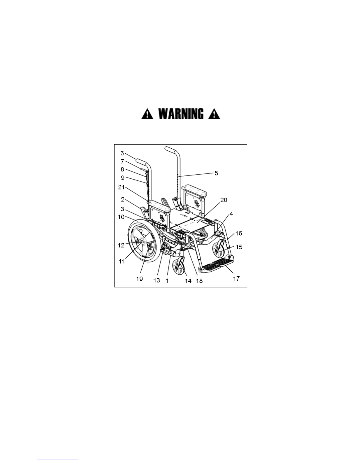
A. Your Focus CR It’s Parts
1. Inspect and maintain this chair. See MAINTENANCE on page 46.
2. If you detect a problem, make sure to service or repair the chair before use.
3. Have a complete inspection, safety check and service of your chair performed by an
authorized supplier annually.
WARNING: Failure to read or comply with these instructions may result in damage to your
wheelchair, a fall, or loss of control causing severe injury to the user or others.
1. Base Tube
2. Rotary Frame
3. Seat Tube
4. Caster Arm
5. Back Cane
6. Push Handle
7. Tilt Lock Trigger
8. Tilt Cable
9. Trigger Lock Pin
10. Rear Wheel
11. Quick Release Axle
12. Anti-Tip
13. Wheel Lock
14. Caster Fork
15. Caster Wheel
16. Swing Away Hanger
17. Footrest
18. Swing Away Lever
19. Axle Plate
20. Seat Pan
21. Dual Post Armrest
Page 15

14
V. SET UP & USE OF YOUR WHEELCHAIR
B. Transit Use
It is always safest to transfer out of your wheelchair onto a seat in a motor vehicle with appropriate
seat and shoulder belts. Never use this wheelchair as a seat in a motor vehicle unless it has
been equipped with the Transit Option.
The Focus CR wheelchair equipped with the Transit Option has been tested to and passed the
RESNA WC-4:2012, Section 19: Wheelchairs used as seats in motor vehicles and ISO 717619:2008 Wheelchairs -- Part 19: Wheeled mobility devices for use as seats in motor vehicles.
RESNA and ISO standards are designed to test the structural integrity of the wheelchair as a seat
for use in a motor vehicle. These standards are also designed to create compatibility with
Wheelchair Tie-down and Occupant Restraint Systems (WTORS).
Not all configurations of the Focus CR wheelchairs are compatible with the Transit Option. Ki
Mobility manages the configuration and does not offer the Focus CR wheelchair except in
compatible configurations. If you make changes to your Focus CR wheelchair after you receive it,
you should contact your wheelchair provider or Ki Mobility to make sure it is appropriate to
continue to use your wheelchair as a seat in a motor vehicle.
Aftermarket seating may have replaced the original equipment seat and back support designed
and tested as part of the Transit Option. Your wheelchair provider should tell you if the seating they
provided is original equipment or replacement aftermarket seating. A complete system of
wheelchair frame, seating, Wheelchair Tie-down and Occupant Restraint Systems and a properly
equipped motor vehicle, that have all complied with the standards mentioned in this section,
should be in place before using a Focus CR wheelchair equipped with the Transit Option as a seat
in a motor vehicle.
When using your wheelchair as a seat in a motor vehicle you should always observe the following
instructions:
• The rider must be in a forward-facing position.
• The rider and all items carried must not weigh more than 300 lbs (400 lbs for Heavy Duty
option).
• Backpacks and pouches should be removed and secured separately in the motor vehicle.
In the event of an accident these items can become dangerous projectiles, which may
injure or kill you or other occupants of the motor vehicle.
Page 16
15
V. SET UP & USE OF YOUR WHEELCHAIR
B. Transit Use
• The rider must use a Wheelchair Tie-down and Occupant Restraint System that complies
with RESNA WC-4:2012, Section 18: Wheelchair tie-down and occupant restraint
systems for use in motor vehicles or ISO 10542-1:2012 Technical systems and aids for
disabled or handicapped persons -- Wheelchair tie-down and occupant-restraint
systems -- Part 1: Requirements and test methods for all systems.
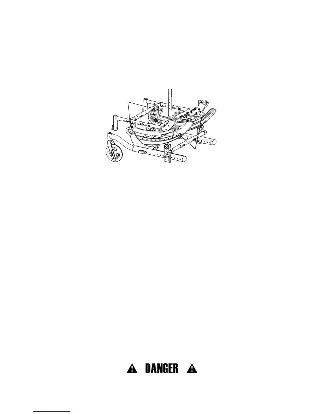
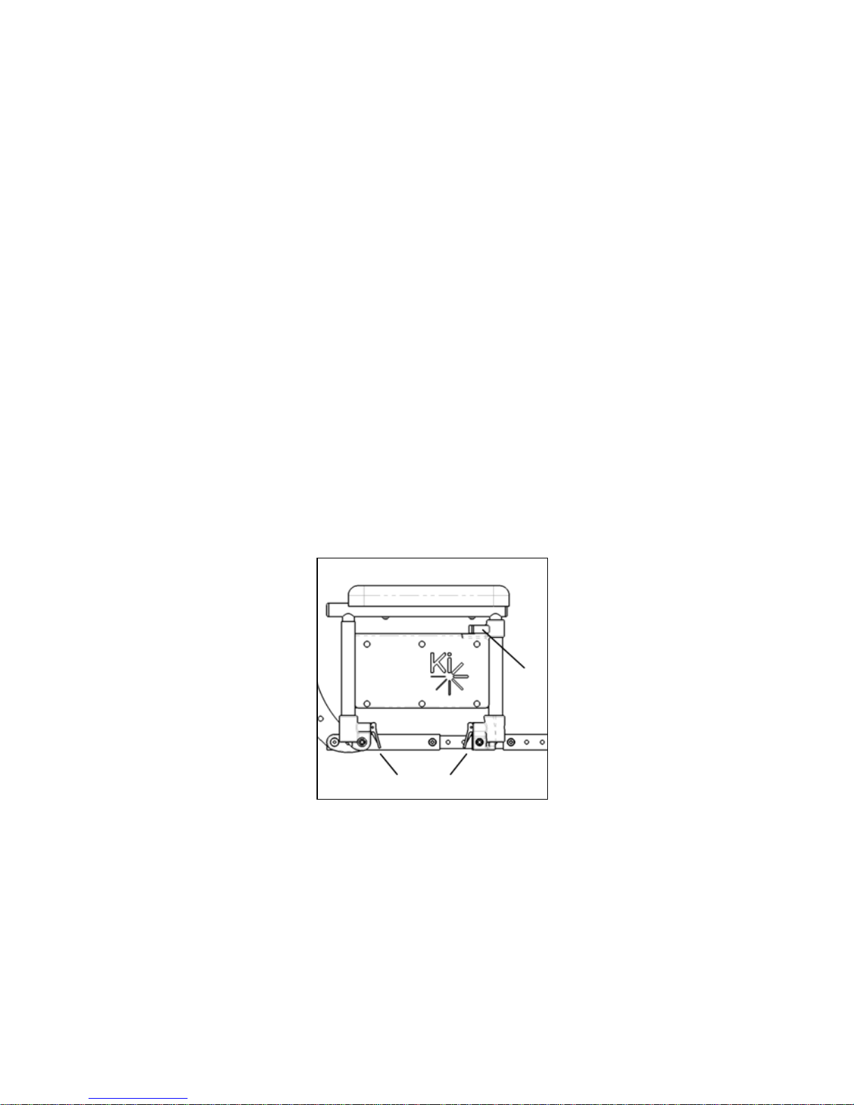
• Attach wheelchair tie-downs to the four securement points (two front, two rear) on the
Focus CR wheelchair with the Transit Option (Fig. 1) in accordance with the wheelchair tiedown manufacturer’s instructions and RESNA WC-4:2012, Section 18 or ISO 10542-
1:2012 - Part 1.
• Attach occupant restraints in accordance with the occupant restraint manufacturer’s
instructions and RESNA WC-4:2012, Section 18 or ISO 10542-1:2012, Part 1.
• Use of lap belts, chest straps, shoulder harnesses, any other positioning strap system or
positioning accessory should not be used, or relied on as an occupant restraint, unless it is
marked as such by the manufacturer in accordance with RESNA WC-4:2012, Section 18
or ISO 10542-1:2012, Part 1.
• Use of headrests, lateral supports or other positioning accessories should not be used, or
relied on as an occupant restraint, unless it is marked as such by the manufacturer in
accordance with RESNA WC-4:2012, Section 18 or ISO 10542-1:2012, Part 1 or RESNA
WC-4:2012, Section 20: Wheelchair seating systems for use in motor vehicles or ISO
16840-4:2009 Wheelchair seating -- Part 4: Seating systems for use in motor vehicles.
• Any aftermarket seating should be tested to comply with RESNA WC-4:2012, Section 20
or ISO 16840-4:2009 - Part 4.
• Attach the seating to the wheelchair frame in accordance with the seating manufacturer’s
instructions and RESNA WC-4:2012, Section 20 or ISO 16840-4:2009 - Part 4.
• Aftermarket accessories such as trays, oxygen tank holders, oxygen tanks, IV poles, back
packs, pouches and other items not manufactured by Ki Mobility should be removed and
secured separately in the motor vehicle. In the event of an accident, these items can
become dangerous projectiles which may injure or kill you or other occupants of the motor
vehicle.
• If the wheelchair has been involved in an accident, you should not continue to use it, as it
may have suffered fatigue that may not be visible.
DANGER: Failure to comply with any of these instructions could result in severe injury or death!
Securement
Points
Securement
Points
Fig. 1
Page 17

16
V. SET UP & USE OF YOUR WHEELCHAIR
B. Transit Use
• When using this wheelchair as a seat in a motor vehicle, you must remove any items
attached to the vent tray, battery tray or oxygen tank holder and properly secure them
separately.
DANGER: Failure to remove items attached to the vent tray, battery tray or oxygen tank holder
and properly secure them separately in the motor vehicle can result in these items becoming
dangerous projectiles in the event of an accident. Oxygen tanks contain a highly pressurized gas
that vigorously accelerates combustion. Failure to heed this warning can result in severe injury or
death.
• If the chair is equipped with an oxygen tank holder never use the wheelchair as a seat in a
motor vehicle.
DANGER: Using a Focus wheelchair equipped with an oxygen tank holder as a seat in a motor
vehicle can result in severe injury or death.
NOTE: To obtain copies of RESNA or ISO standards please contact the standards organizations
below:
RESNA
1700 N Moore St Ste 1540
Arlington, VA 22209
Phone: 703-524-6686
Fax: 703-524-6630
Email: technicalstandards@resna.org
ANSI/RESNA Standards:
RESNA WC-4:2012, Section 18:
Wheelchair tie-down and occupant restraint systems for use in motor vehicles.
RESNA WC-4:2012, Section 19:
Wheelchairs used as seats in motor vehicles.
RESNA WC-4:2012, Section 20:
Wheelchair seating systems for use in motor vehicles.
International Organization for Standardization (ISO)
ISO Central Secretariat
1, ch. de la Voie-Creuse
CP 56
CH-1211 Geneva 20 Switzerland
Phone: +41 22 749 01 11
Fax: +41 22 733 34 30
Email: central@iso.org
ISO Standards:
ISO 10542-1:2012 Technical systems and aids for disabled or handicapped persons --
Wheelchair tie-down and occupant-restraint systems -- Part 1:
Requirements and test methods for all systems.
ISO 16840-4:2009 Wheelchair seating – Part 4:
Seating systems for use in motor vehicles.
ISO 7176-19:2008 Wheelchairs – Part 19:
Wheeled mobility devices for use as seats in motor vehicles.
Page 18
17
V. SET UP & USE OF YOUR WHEELCHAIR
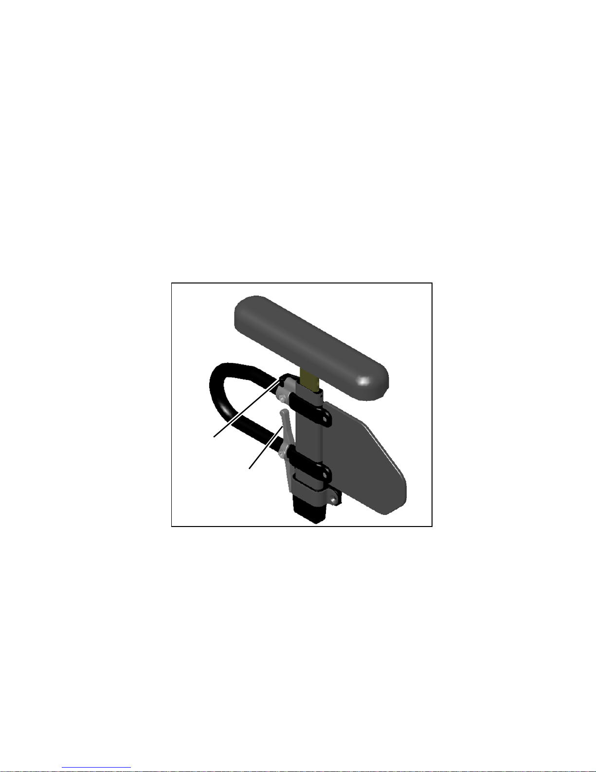
C. Height Adjustable T-Arms
1. Installation
a. Slide the outer armpost into the receiver mounted to the wheelchair frame.
b. The armrest will automatically lock into place. Check to make sure the locking lever is as
shown (Fig. 2:B).
2. Height Adjustment
a. Rotate release lever (Fig. 2:A).
b. Slide armrest pad up or down to desired height.
c. Return lever to locked position against arm post.
d. Push arm pad until upper arm locks firmly into place. Check to make sure the locking lever
is as shown (Fig. 2:A).
3. Removing Armrest
a. Squeeze release lever (Fig. 2:B) and remove the armrest.
Fig. 2
A
B
Page 19
18
V. SET UP & USE OF YOUR WHEELCHAIR
C. Height Adjustable T-Arms
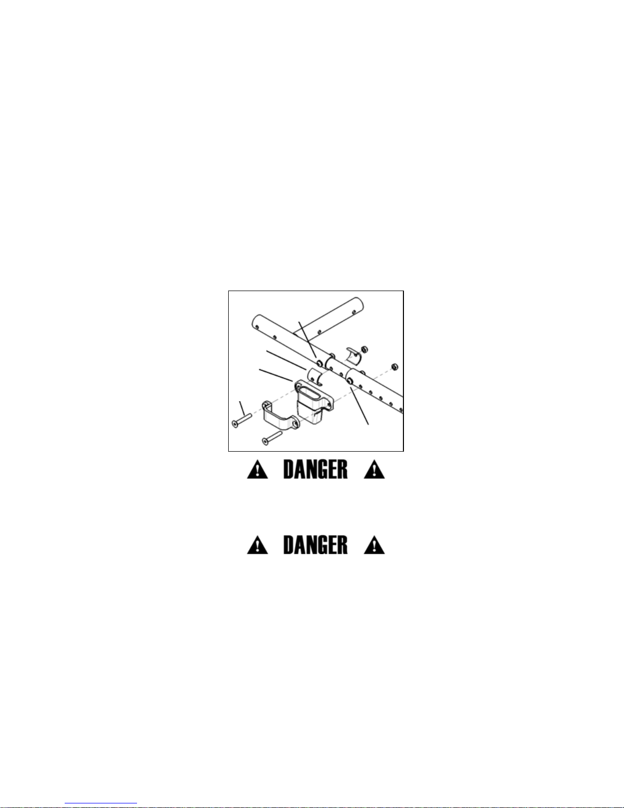
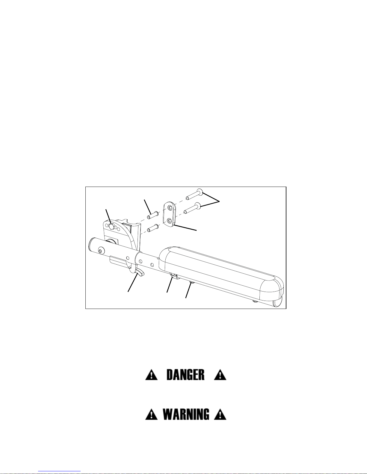
4. Adjusting Position
a. Remove both screws (Fig. 3:A) from each armrest receiver (Fig. 3:B) retaining the spacers
(Fig. 3:C) if installed. If not installed at factory, they are included in a separate bag in the
packaging.
b. Move receiver to desired location on seat frame and reinstall screws with washers and nuts
and tighten.
c. If screws for new armrest receiver location coincide with seat frame screws (Fig. 3:D and E),
remove seat frame screws and replace with armrest receiver screws. Retain (do not discard)
these screws for potential future use, or optionally, they may be retained by reinstalling them
in an alternate location on the seat frame.
d. If one of the armrest receiver screws lies on the center growth section of the seat frame, be
sure to use the spacers (as described in step 1) around growth tube in location of mounting
hole.
DANGER: Failure to comply with the instructions above may result in the armrest accidently
disconnecting from the wheelchair and result in a fall or loss of control and may cause serious
injury or death.
DANGER: Never attempt to lift the chair by the armrests; they may break or disconnect resulting
in a fall or loss of control and may cause serious injury or death.
Fig. 3
A
B
C
D
E
Page 20
19
V. SET UP & USE OF YOUR WHEELCHAIR
D. Dual Post Height Adjustable Armrest
1. Installation
a. Ensure both levers (Fig. 4:A and B) are flipped upward.
b. Set both posts of armrest into receivers until they are seated against the bottoms of the
receivers.
c. Flip levers back downward. Ensure locking pins are seated by lifting on armrest.
2. Height Adjustment
a. Flip lever (Fig. 4:C) forward at the top of the front post of the lower frame of the armrest.
b. Adjust height of armrest by pushing down or pulling upwards on arm pad near the center
between the two posts of the armrest.
c. When proper height is achieved, flip lever rearward again and move armrest up or down to
allow pin to seat in nearest hole.
3. Flipping Back Armrest
a. Flip lever (Fig. 4:A) on front armrest receiver.
b. Lift upwards on arm pad and cross tube, allowing the armrest to flip back.
NOTE: Do not push outward or backward on armrest when it is flipped back or damage to rear
receiver may occur.
4. Removal
a. Flip the levers (Fig. 4:A and B) on both receivers upward.
b. Lift armrest out of receivers by pulling up on arm pad and cross tube.
A
B
C
Fig. 4
Page 21
20
V. SET UP & USE OF YOUR WHEELCHAIR
E. Angle Adjustable Locking Flip Up Extendable Armrest
Adjustments
1. Set the angle of the armrest based on your preferences. There are five holes that can be used
to set the angle (Fig. 5:A). Tighten the bolt once angle is set.
2. Set the length of the armrest based on your preferences. To adjust the length, remove the
bolts and spacer (Fig. 5:B) on the tube and the screw (Fig. 5:C) closest to the back of the
chair. Slide the armrest to desired length available by the predrilled holes and reinstall the
screw and bolts.
3. Set the height of the armrest on the chair based on your preferences. There are four holes on
the armrest that allow for two different height settings for each set of holes on the back tube.
Use the holes that provide the correct height setting for the user. The two bolts (Fig. 5:D) pass
through the spacer (Fig. 5:E), sleeves (Fig. 5:F), back posts and into the armrest.
Use
1. Press the release lever (Fig. 5:G) up to release the armrest and swing it upwards.To return the
armrest to the operating position, push the armrest down until the lever clicks and locks.
F. Armrest Warnings
• All Ki Mobility armrests are designed to detach from the chair and will not bear even the
weight of this chair.
• NEVER lift this chair by its armrests. The armrests will release and the user may fall.
• Lift this chair only by non-detachable parts of the main frame.
DANGER: Always make sure the arms are locked in place before using them for repositioning
yourself, failure to do so may result in a fall or loss of control and may cause serious injury or
death.
WARNING: Failure to heed these instructions may result in a fall, tip-over or loss of control
causing severe injury to the user or others.
A
C
B
D
E
G
F
Fig. 5
Page 22
21
V. SET UP & USE OF YOUR WHEELCHAIR
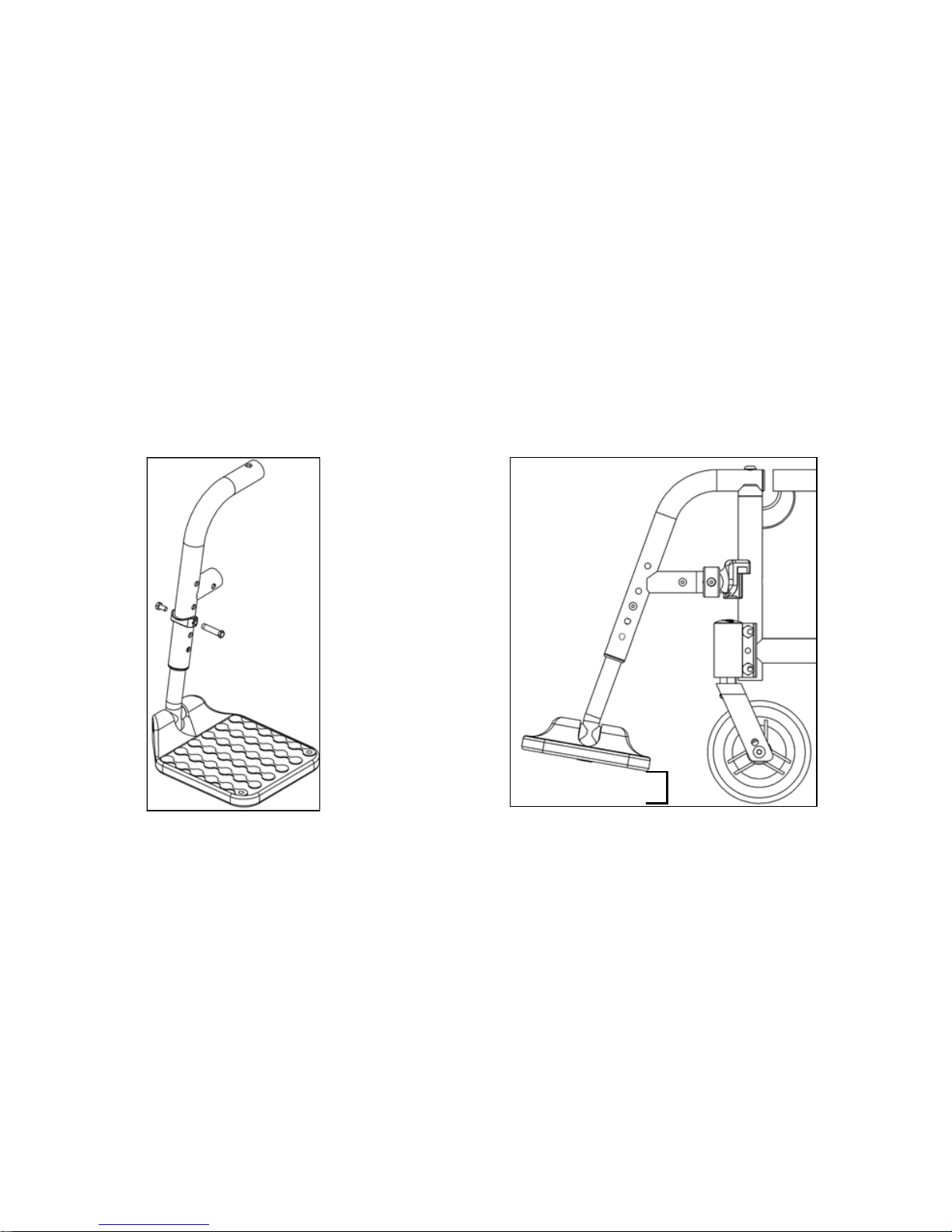
G. Swing Away Hangers
1. Installation
a. Place swing away pivot saddle into the receiver on front frame tube with the footrest facing
either inward or outward from the frame (Fig. 6).
b. Rotate the footrest so that it aligns with the frame until it locks into place in the latch block
(Fig. 7).
2. Swinging the Footrest Away
a. Push release latch toward the frame.
b. Rotate footrest outward or inward as desired.
3. Removal
a. To remove footrest, push release latch toward the frame.
b. Lift the footrest straight upward to remove. You may also swing the footrest inward or out-
ward before lifting it off.
WARNING: Always make sure the hangers are locked in place before using them or riding the
wheelchair. Failure to do so may result in a fall or loss of control and may cause serious injury or
death.
DANGER: Never attempt to lift the chair by the hangers; they may break or disconnect resulting
in a fall or loss of control and may cause serious injury or death.
Fig. 6
Fig. 7
Page 23
22
V. SET UP & USE OF YOUR WHEELCHAIR
H. Swing Away Hangers with 4-Way Latch
1. Installation
a. Place swing away pivot saddle into the receiver on front
frame tube (Fig. 8:A).
b. Rotate the footrest so that it aligns with the frame and locks
into place in the latch block (Fig. 8:B).
2. Swinging the Footrest Away
a. Push or pull on release latch.
b. Rotate footrest outward or inward as desired.
3. Removal
a. To remove footrest, push or pull release latch.
b. Lift the footrest straight upward to remove. You may also
swing the footrest inward or outward before lifting it off.
4. Rotating (Fig. 9)
The 4-way latch has eight possible configurations, four with the
curve of the lever facing outward and four with the curve of the lever
facing inward. See Fig. 10 for possible configurations.
a. To rotate the 4-way latch, remove the screw using a 3mm Allen wrench while the hanger is
still on the chair (spring must be engaged to remove and reinsert screw and keeping the
hanger on the chair keeps the spring engaged). Ensure nut does not fall out.
b. Rotate the 4-way latch to desired orienta-
tion and reinsert screw with 3mm Allen
wrench. Ensure that nut stays in position
while tightening the screw. Do not overtighten screw or mechanism will bind.
NOTE: To reverse the 4-way latch, the same
screw is removed, but the hanger has to be
removed from the latch block. Once removed,
slide the latch off, flip over and reinstall. Ensure spring is engaged, by pushing and holding the
latch button in, and nut stays in position while reinstalling the screw.
NOTE: In-line position is not achievable with the Pro ELR Footrest option.
Fig. 8
A
B
Screw
Nut
Fig. 9
Eight Possible Configurations
Lever Facing
Outward
Lever Facing
Inward
Standard Position
Fig. 10
Page 24
23
V. SET UP & USE OF YOUR WHEELCHAIR
I. Extension Tubes
1. Adjustment
a. Remove mounting fasteners from each side of the hanger tube.
b. Slide footrest extension tube to the desired height.
c. Line up holes and reassemble fasteners in desired hole through hanger and extension tube.
d. Follow same procedure on opposite side (Fig. 11).
At the lowest point, footrests should be AT LEAST 2 ½ INCHES off the ground. If set too low, they
may "catch" on obstacles you would expect to find in normal use. This may cause the chair to
stop suddenly and tip forward (Fig. 12).
To Avoid a Trip or Fall When You Transfer:
• Make sure your feet do not get caught in the space between the footrests.
• Avoid putting weight on the footrests as the chair may tip forward.
Fig. 11
Fig. 12
2.5"
Page 25
24
V. SET UP & USE OF YOUR WHEELCHAIR
J. Elevated Leg Rest
1. Installation
a. Place swing away pivot saddle into the
receiver on front frame tube with the footrest facing either inward or outward from
the frame. Similar to swing away footrest
pictured in Fig. 6 and 7.
b. Rotate the footrest so it aligns with the
frame until it locks into place in the latch
block.
2. Removal
a. To remove footrest, push release latch
toward the frame.
b. Rotate footrest outward and lift.
3. Extension Tube Adjustment
a. Remove mounting bolt that is threaded
into the leg rest tube in the center of the pad bracket (Fig. 13:C). In some circumstances this
bolt may be inserted in the tube below below the pivot bracket.
b. Slide footrest extension tube to the desired height.
c. Line up holes and replace the bolt through the leg rest tube and extension tube.
d. Follow same procedure on opposite side.
4. Angle Adjustment
a. To raise, lift up on the rear of the extension tube (Fig. 13:A). The rod will slide through the
ratchet in this direction. Stop at desired position.
b. To lower, firmly hold the leg from behind the extension tube (Fig. 13:A). Pull forward on the
lever (Fig. 13:B) and while holding the lever, lift the leg rest. Releasing the lever will cause the
leg rest to lock into position.
To Avoid a Trip or Fall When You Transfer:
• Make sure your feet do not get caught in the space between the footrests.
• Avoid putting weight on the footrests as the chair may tip forward.
WARNING: At the lowest point, footrests should be AT LEAST 2 ½ INCHES off the ground. If set
too low, they may "catch" on obstacles you would expect to find in normal use. This may cause
the chair to stop suddenly and tip forward and could result in a fall or loss of control and may
cause serious injury or death.
DANGER: Never attempt to lift the chair by the hangers; they may break or disconnect resulting
in a fall or loss of control and may cause serious injury or death.
Fig. 13
B
C
A
Page 26
25
V. SET UP & USE OF YOUR WHEELCHAIR
K. Pro Elevated Leg Rest
Installation
NOTE: The Pro ELR is mounted onto the chair the same way as a swing away hanger.
1. Place swing away pivot saddle into the receiver on front frame tube with the leg rest facing
either inward or outward from the frame.
2. Rotate the leg rest so that it aligns with the frame and locks into place in the latch block.
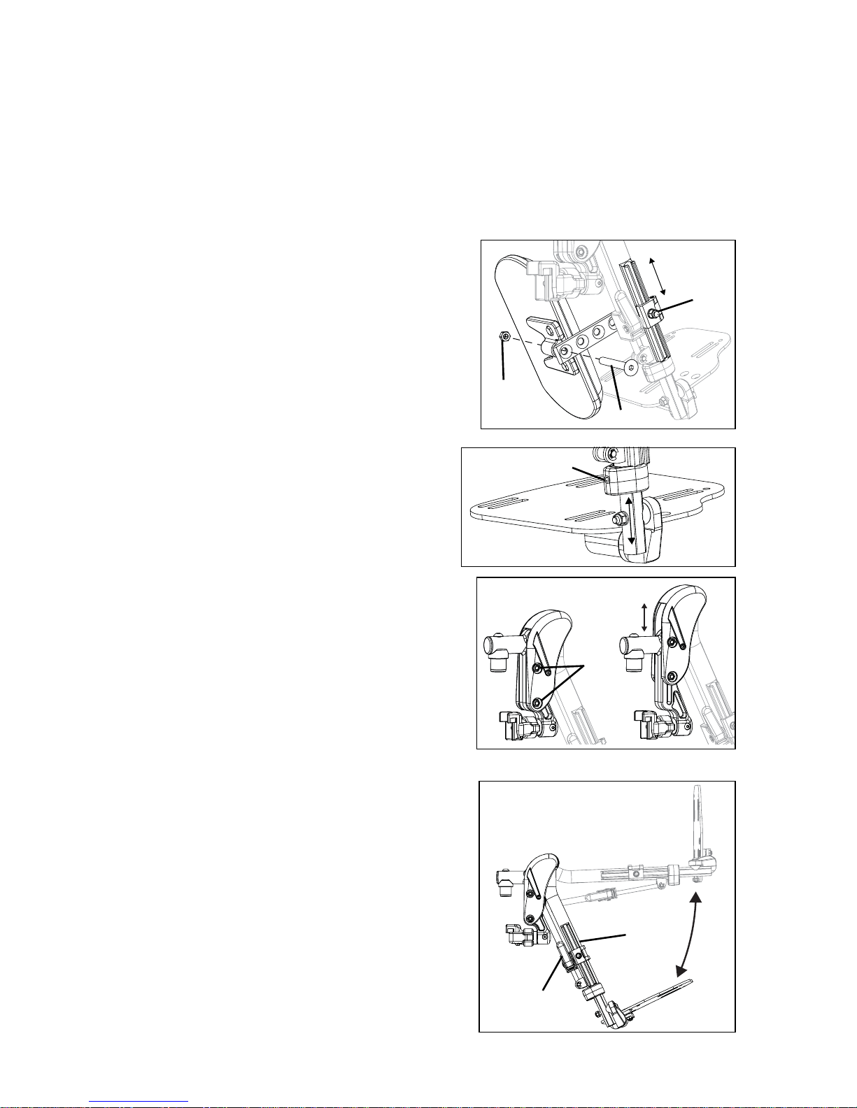
Adjusting Height of Calf Pad
1. Loosen nut (Fig. 14:A) using a 10mm wrench.
2. Slide calf pad arm up or down to desired location.
Retighten nut.
Adjusting Depth of Calf Pad
1. Remove screw (Fig. 14:B) and nut (Fig. 14:C) on calf
pad arm using a 5mm Allen wrench and a 13mm
wrench.
2. Pick the desired location based on the four predrilled
holes and reinstall screw and nut.
Adjusting Length of Footrest
1. Loosen set screw (Fig. 15:A) with a 4mm Allen
wrench.
2. Slide extension tube in or out to get to desired
length and secure by tightening set screw.
Adjusting Knee Height
1. Using two 10mm socket wrenches, loosen the two
nuts (Fig. 16:A) on the cover.
2. Adjust knee height to desired setting.
3. Retighten the two nuts (Fig. 16:A) after desired
height is attained.
Use
1. To raise the Pro ELR, lift the leg rest tube (Fig. 17:A)
to desired angle of elevation.
2. To lower the Pro ELR, press and hold the lever lock
(Fig. 17:B) while pushing the leg rest tube (Fig. 17:A) down.
NOTE: Remove the Pro ELR from the chair or remove
weight from the Pro ELR while lowering to avoid a
sudden drop when the lever lock is pushed.
NOTE: The calf pad can swing outward to clear the
front of the chair for transfers.
Removal
1. To remove leg rest, push or pull release latch.
2. Lift the leg rest straight upward to remove. You may
also swing the leg rest inward or outward before
lifting it off.
Fig. 14
A
B
C
Fig. 15
A
1 ½”
range of
motion
Fig. 16
A
Fig. 17
A
B
Page 27
26
V. SET UP & USE OF YOUR WHEELCHAIR
L. Backrest
1. Folding Backrest Down
a. If chair is equipped with a fold down backrest, push
levers (Fig. 18:A) toward the front of the chair to disengage the latches. If backrest seating is attached,
both latches must be disengaged simultaneously in
order to allow the backrest to fold.
b. Push forward on the backrest to rotate it downward.
Once it begins to rotate forward, the latch levers may
be released.
2. Angle Adjustment
a. Using a 4mm Allen wrench and a 10mm wrench,
remove button head screws (Fig. 19:A) with their
washers and nuts.
b. Rotate backrest to desired angle. Each hole rep-
resents 5° of rotation. The upper row of holes correspond to -5°, 5°, 15° and 25° and the lower row of
holes correspond to 0° (vertical), 10° and 20° (Fig.
20).
c. Replace button head screw and tighten with washer
and nut.
d. Repeat for opposite side of chair.
Fig. 18
A
Fig. 19
A
Fig. 20
5°
-5°
15°
25°
20°
10°
0°
Page 28
27
V. SET UP & USE OF YOUR WHEELCHAIR
L. Backrest
3. Adjusting Height
a. If chair is equipped with a height adjustable backrest, remove
both screws (Fig. 21:A) of the telescoping backrest tubes
using a 4mm Allen wrench and a 10mm wrench.
b. Move upper tubes up or down to set height as desired.
c. Replace screws with washers and nuts to set height.
4. Push Handle Angle Adjustment
a. If chair is equipped with a height adjustable backrest, push
buttons of locking hinges (Fig. 21:B). Both buttons must be
pressed simultaneously to adjust angle.
b. While holding buttons down, rotate push handle to desired
position.
c. Release buttons when desired angle is achieved.
d. Verify that hinge is locked by pulling upwards on push handles.
5. Removable Stroller Handle
a. Depress buttons (Fig. 22:A) on both sides of chair toward lower
end of stroller tubes to disengage locking tabs.
b. Pull handle out of receivers to remove or push stroller handle in
to receivers to install. For best results, insert both sides at the
same time.
c. Verify snap buttons are engaged in receivers.
DANGER: Do not attempt to lift or tilt the wheelchair by holding the center strut that joins the
Adjustment Height Back push handles (Fig. 21:C) or the center strut that joins Removable Stroller
Handle push handles (Fig. 22:B). These struts may break resulting in a fall or loss of control and
may cause serious injury or death.
6. Dynamic Back
a. See instructions for this back provided separately with chair.
Fig. 21
A
C
B
Fig. 22
A
B
Page 29

28
V. SET UP & USE OF YOUR WHEELCHAIR
M. Reclining Backrest
WARNING: Back height, back angle, seat depth, tilt angle, recline angle, seat height,
size/position of rear wheels, size/position of front casters and any added weight to the back of the
chair such as accessories, backpacks and oxygen tanks all relate to and affect the stability of the
wheelchair. Any adjustments or change to one or more of the items listed above can decrease the
stability of the wheelchair. Take caution when making changes to the above items. Consult a
qualified technician when adjusting back height, back angle, seat depth, seat height, size/position
of rear wheels and size/position of front casters. Inappropriate adjustments can result in serious
injury.
Reclining Back Notes for Operation
1. After making any adjustments to the system make sure all attaching hardware is securely
tightened.
2. Always make sure the wheelchair is stable in the fully reclined position. Depending on the
angle of the backrest, the full recline position can be 85°, 75° or 65° and is relative to the full
upright position. Full upright position is measured as 0°.
3. In order to ensure maximum safety and security for the patient in the chair, it is important to
make sure the patient is properly positioned before reclining or inclining (sitting up) the
backrest.
4. Always engage the wheel locks while reclining or inclining to ensure maximum safety of the
patient.
5. Before using the reclining backrest, make sure that the anti-tippers are adjusted properly to
ensure the wheelchair will not become unstable when in use. See anti-tip instructions on page
42 of this owner’s manual.
DANGER: Tilting or reclining the chair beyond level greatly increases the risk of falling out of the
chair, which can result in serious injury or death.
Page 30
29
V. SET UP & USE OF YOUR WHEELCHAIR
M. Reclining Backrest
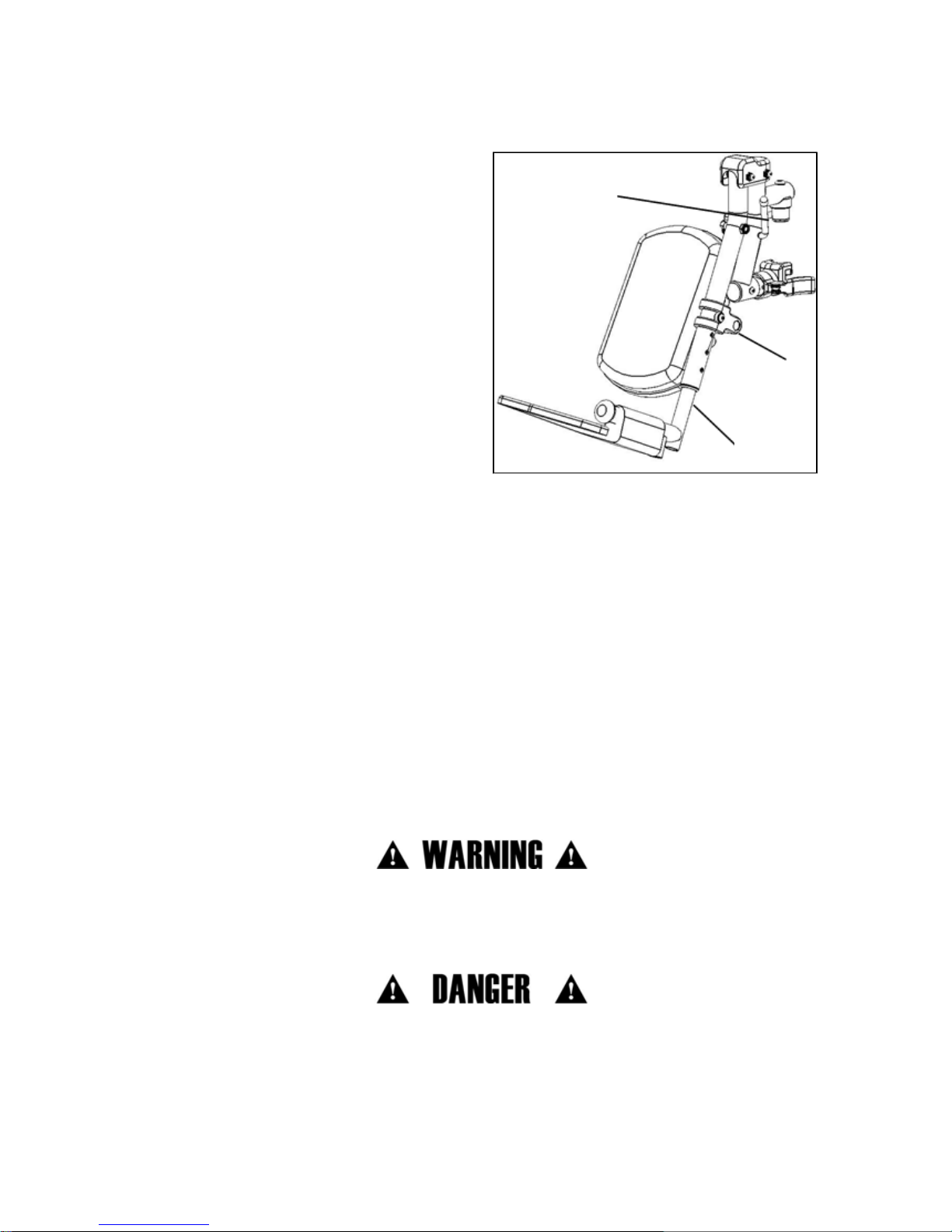
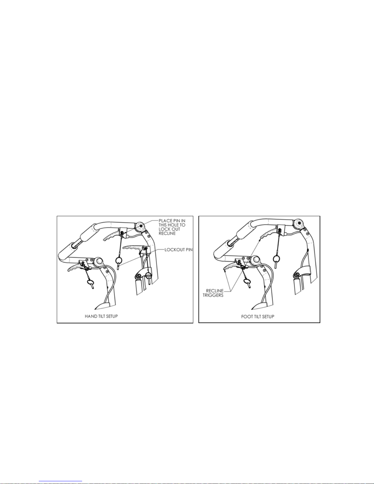
Instructions for Use:
Recline / Incline:
1. To unlock the system prior to recline or incline adjustment by removing the locking pin from
locking hole on each recline trigger (Fig. 23).
2. Make sure wheel locks are engaged and wheelchair is on a level surface.
3. Grip the handles securely and slowly depress both reclining triggers (Fig. 24) at the same
time to release the gas cylinders. This will allow you to adjust the backrest position as
follows:
a. Reclining - to open the angle of the backrest relative to the seat frame, or recline, by apply-
ing downward force on gas springs.
b. Inclining - return to upright position by applying force upward and pushing the backrest
towards the front of the wheelchair.
4. Once desired backrest recline angle has been achieved, slowly release both reclining
triggers.
5. To lock the system, insert the locking pin into the locking pin hole (Fig. 23). It is
recommended that you always lock both reclining backrest triggers when you are done
positioning the patient.
Fig. 23
Fig. 24
Page 31

30
V. SET UP & USE OF YOUR WHEELCHAIR
M. Reclining Backrest
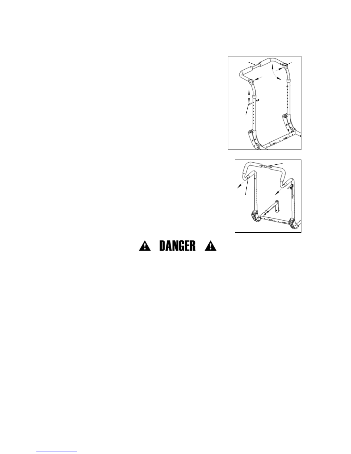
Angle Adjustment of Recline Backrest Plates:
WARNING: Remove patient from wheelchair prior to making this adjustment. Failure to do so
could result in death or serious injury.
1. The reclining option comes with three different backrest angle adjustment options. See
Fig. 25 for range information prior to making the adjustment.
2. Using a 4mm Allen wrench and a 10mm wrench, remove button head screws (Fig. 25) with
their washers and nuts.
3. Rotate backrest to desired angle. Each hole represents 65° of rotation (Fig. 25).
4. Replace button head screw and tighten with washer and nut until securely fastened.
5. Repeat for opposite side of chair.
Fig. 25
Page 32

31
V. SET UP & USE OF YOUR WHEELCHAIR
N. Tilt Mechanism
1. Hand Operated (Trigger) Tilt
a. Tilting Seat Frame
i. Squeeze trigger (Fig. 26:A).
ii. While keeping triggers depressed, rotate seat frame to
desired position.
iii. Release trigger to lock into place.
b. Cable Adjustment
i. Unlock jam nut (Fig. 26:B) from cable adjuster body (Fig. 26:C)
using a 10mm and 3/8" open ended wrench.
ii. Thread cable adjuster (Fig. 26:D) in or out until slack in cable
is eliminated but also such that the cogs are still fully seated in
the teeth of the rotary frames.
iii. Verify function of the cable. Tilt mechanism should lock at all
locations and cogs should not drag along the teeth at any location. If the cogs drag or if
there is excessive play in the triggers, the male adjuster must be unthreaded more. If the
cog is disengaged at all from the teeth, the adjuster must be threaded into the body further.
iv. Once cable is adjusted and function is verified, re-lock the jam nut against the cable
adjuster body by tightening the nut only, not the male adjuster or the adjuster body.
c. Locking Triggers
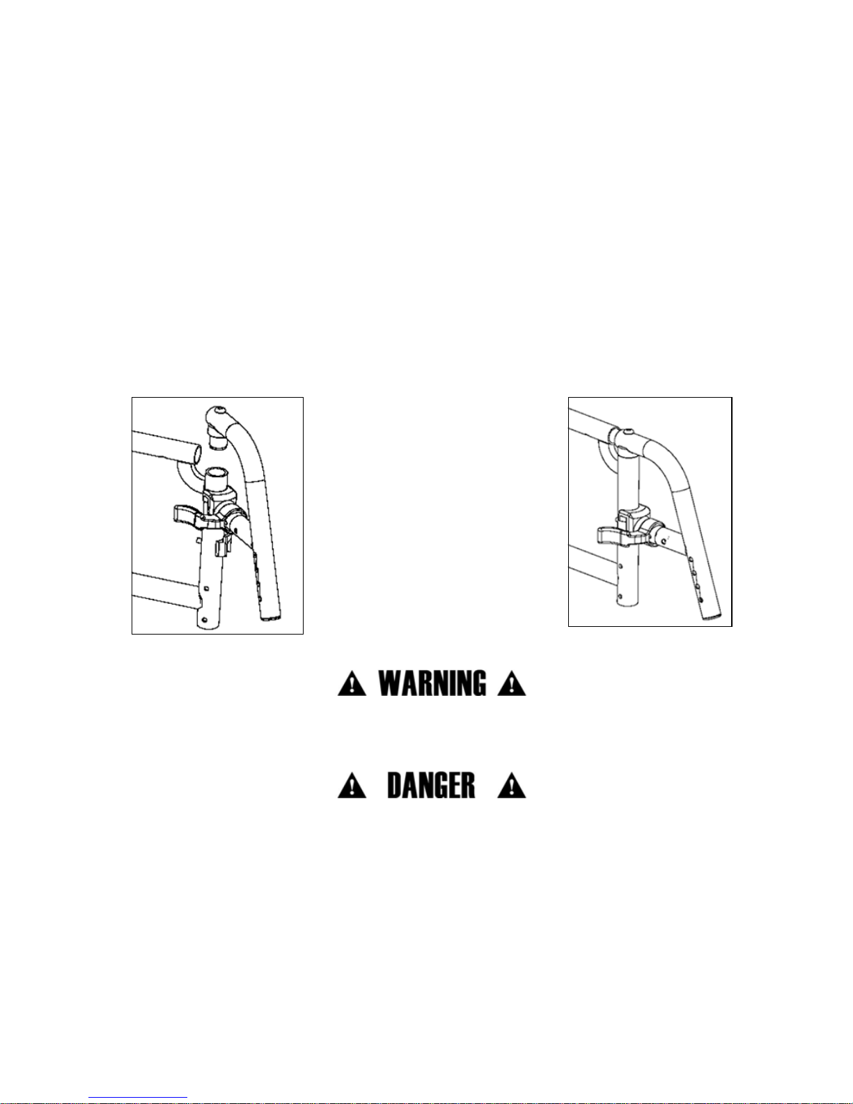
i. To secure the triggers in the locked position:
a. Determine which style back canes and trigger
were provided with the chair by checking
against Fig. 27 and 28.
b. Make sure the chair is locked by pushing on
the back handles.
c. Insert the pin attached to the trigger by a lanyard into hole
number 1.
d. Make sure the trigger no longer releases the tilt locks by gen-
tly squeezing the trigger and pushing on the back canes to tilt
the chair.
ii. To secure the triggers in the unlocked position:
a. Determine which style back canes and trigger were provided
with the chair by checking against Fig. 27 and 28.
b. Squeeze the triggers to unlock the tilt mechanism while hold-
ing the back canes and controlling the tilt position.
c. Allow the seat frame to tilt until it comes to rest in a stable position.
d. Insert the pin attached to the trigger by a lanyard into hole number 2 (Fig. 27:A
and B).
NOTE: This feature is intended to be used solely for the purposes of adjusting CG which is
covered in Section V: O: CG (Center of Gravity) Optimization.
WARNING: Never leave someone seated in the chair unattended with the triggers secured in the
unlocked position. This may lead to serious injury to the person seated in the wheelchair.
A
D
B
C
Fig. 26
A
B
Fig. 27
Fig. 28
A
B
Page 33

32
V. SET UP & USE OF YOUR WHEELCHAIR
N. Tilt Mechanism
2. Foot Operated Tilt
a. Tilting Seat Frame
i. Depress foot tilt pedal (Fig. 29:A).
ii. Rotate seat frame to desired position
while keeping pedal depressed.
iii. Release pedal to lock into place.
b. Linkage Adjustment
i. Using a 3mm Allen wrench, loosen lock-
ing collar (Fig. 29:B) by loosening screw
in collar.
ii. With cog (Fig. 29:C) fully engaged in
rotary frame teeth and with tilt pedal
released, reposition locking collar against end of tube (Fig. 29:D) and tighten clamp
screw.
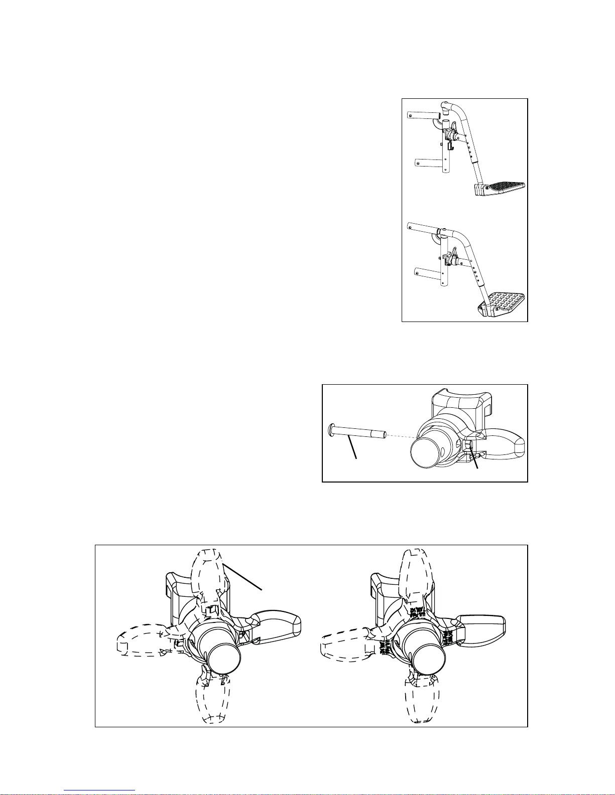
3. Tilt Stops
a. Place tilt stop pads (Fig. 30:A) on both sides of
each rotary frame (Fig. 30:B) at desired location. Pads should nest together.
b. Place thrust plates (Fig. 30:C) into pockets on
pads.
c. Insert and tighten screw (Fig. 30:D) with nut
and washer to lock into place.
d. To change, remove tilt stops and reassemble
according to the instructions above at the new desired location.
NOTE: Cable actuated mechanisms
require periodic maintenance (See Fig. 31).
Verify that cables are:
• Adjusted properly.
• Routed correctly.
• Bends in the cable are minimized to
reduce friction.
• Replace the cables if they have any
kinks or cannot be adjusted.
A
D
B
C
Fig. 29
A
B
C
D
Fig. 30
Cable
Adjuster
Minimize
Bend
Minimize
Bend
Minimize
Bend
Fig. 31
Page 34

33
V. SET UP & USE OF YOUR WHEELCHAIR
O. Seat Frame Set Up
1. Setting Seat Depth
a. Using a 5mm Allen wrench and a 13mm wrench, remove depth adjustment screws from
seat pan, or remove seat seat pan (See Section W).
b. Using a 4mm Allen wrench and a 10mm wrench, remove button head screw (Fig. 32:A) with
nut and washer from front seat frame (Fig. 32:B) on each side of chair.
c. Slide rear seat frame in or out as desired to set the seat depth.
d. Replace button head screws in new location, placing screws in rearmost hole in front seat
frame.
2. CG (Center of Gravity) Optimization
a. Place occupant in chair, with all equipment that attaches to upper frame, such as foot
boxes, backpacks, etc.
b. Lock wheel locks (if equipped).
c. Squeeze triggers (if hand operated tilt) or depress foot pedal (if foot operated tilt). Lock trig-
gers in this position using locking pins (See Section N. Step 1 -C.), or if foot operated tilt,
use a zip tie or other means of holding foot pedal down.
d. Allow rotary frame to find its resting place. A slight rocking motion applied to the push han-
dles can be used to determine where the center of the resting place lies.
e. Observe the tilt angle by viewing the angular scale on the side of the rotary frame. The angle
is indicated by the rear edge of the bearing plate (Fig. 32:C). Resting angle for optimum performance is 17-23°. If frame rests outside of this range, remove the seat frame position
locking screws (Fig. 32:D) using a 5mm Allen wrench.
f. If resting angle is larger than 23°, pull seat frame toward the front of the chair until approxi-
mate 20° resting angle is achieved. If frame rests at an angle smaller than 17°, push seat
frame toward the rear until approximately 20° is achieved.
g. Different occupants will respond differently, but a good starting point is to move the seat
frame ½" for every 5° that the angle is off from 20°.
h. Once optimum position is achieved, reinstall and tighten positioning screws in holes closest
to optimum position. Screws may be placed in front or rear hole of seat frame saddle (Fig.
32:E).
A
C
B
D
E
Fig. 32
Page 35

34
V. SET UP & USE OF YOUR WHEELCHAIR
P. Casters
1. Adjusting Caster Arm Position
a. Using 13mm wrench, remove 8mm hex bolt (Fig. 33:A).
b. Slide caster arm (Fig. 33:B) to desired location, aligning holes in caster arm with hole in base
frame.
c. Replace hex bolt thru aligned holes. Nut for bolt is captured in pocket inside of base frame.
d. Ensure both sides are positioned identically.
e. The back of hanger and the receiver tube (Fig. 33:C and 34:C) should not be positioned
beyond the front of the caster stem bearing tube (Fig. 33:D and 34:D) as shown in Fig. 34. If
it does, follow steps A. through D. until it appears as shown in Fig. 33.
NOTE: The hanger receiver may be positioned behind the caster stem bearing tube.
DANGER: Failure to comply with the instructions above may cause the wheelchair to tip forward
during use and result in a fall or loss of control and may cause serious injury or death.
2. Adjusting Caster Height
a. Remove hex bolt (Fig. 35:A) and nut using 13mm
wrenches.
b. Remove caster wheel (Fig. 35:B) and spacers (Fig. 35:C).
c. Feed hex bolt thru desired hole in one side of the caster
fork.
d. Slide one spacer over hex bolt.
e. Slide caster wheel over hex bolt and push hex bolt thru
caster wheel, flush with the opposite side of the caster
wheel bearing.
f. Slide second spacer between caster wheel and caster
fork, aligning spacer with bearing hole.
g. Push hex bolt thru spacer and hole in opposite side of
caster fork.
h. Retighten hex bolt with nut.
i. Repeat for opposite side of chair. Ensure both casters are set up identically.
Fig. 33
A
B
D
C
D
C
Fig. 34
A
C
B
Fig. 35
Page 36

35
V. SET UP & USE OF YOUR WHEELCHAIR
Q. Axle Plate
1. Adjusting Axle Plate Position
a. Using two 13mm wrenches, remove axle plate screws (Fig. 36:A) from both sides of chair,
noting orientation of anti-tip receiver (Fig. 36:B).
b. Slide axle plates (Fig. 36:C) simultaneously forward or rearward to desired location.
c. Replace and tighten axle plate screws.
d. If equipped with foot operated tilt, the tilt lock linkage will need to be readjusted (See Sec-
tion N, Step 2:B).
e. Ensure both axle plates are in the same locations on the base frames.
DANGER: Adjusting the axle plate too far forward can result in a chair that may tip over
backward resulting in a fall or loss of control that could cause severe injury or death.
WARNING: Increasing the seat to back angle will change the center of gravity of the wheelchair.
Make sure your axle position is adjusted properly in order to maintain constant stability of the
wheelchair. Reference instruction for axle plate position at top of page and Fig. 36.
A
B
C
Fig. 36
Page 37

36
V. SET UP & USE OF YOUR WHEELCHAIR
Q. Axle Plate
2. Adjusting Axle Sleeve Height
a. Remove rear wheels.
b. Using two 30mm wrenches, remove axle sleeve nut (Fig. 37:A) and washer (Fig. 37:B) from
outside of axle plate.
c. Remove axle sleeve (Fig. 37:C) from axle plate and reposition in desired height location.
d. Reinstall and tighten axle sleeve nut.
e. Additionally, the axle plate screws may be removed (See step 1) and axle plate may be
moved up or down by 1" by using alternate set of holes in axle plate. Using the lower set of
holes (Fig. 37:D) yields a seat height 1" lower than using the upper set of holes (Fig. 37:E) for
a given axle sleeve location. If moving axle plate up or down, ensure that the anti-tip receiver
(Fig. 37:F) moves up or down (respectively) with the axle plate. All four holes of the anti-tip
receiver should line up with all four holes in the axle plate. See Section V for further instructions on the anti-tip receiver orientation.
f. Ensure that both axle sleeves and axle plates are set up identically.
3. Adjusting Axle Spacing
a. Loosen axle sleeve nut (Fig. 37:A) using two 30mm wrenches.
b. Thread axle sleeve (Fig. 37:C) in and out of nuts to achieve desired wheel spacing.
c. Retighten axle sleeve nuts.
d. Ensure both sides of the chair have the same axle spacing.
e. Changing the axle spacing may require spacing the wheel locks in or out (See Section S).
A
B
C
F
E
D
Fig. 37
Page 38

37
V. SET UP & USE OF YOUR WHEELCHAIR
R. Rear Wheels
1. Installing Wheels
a. Push in the quick release button on the axle to allow the locking balls to retract. Make note
of the difference between the extended and depressed position of the axle release button
and its effect on the locking balls on the other end of the axle (Fig. 38).
b. Insert the axle into the bearing housing on the wheel if it’s separate.
c. Push on quick release button again and slide axle into axle sleeve (Fig. 38).
d. Release the button to lock axle in sleeve. If release button does not fully extend and the
locking balls do not move into the locked position after releasing the button, the axle length
needs to be adjusted (Fig. 39).
2. Adjusting Axles
a. To adjust the axle you will need a 19mm wrench to turn the outside axle nuts.
b. You will also need an 11mm wrench to hold the ball bearings on the opposite end of the
axle and prevent the axle from turning.
c. When the wheel is installed, if the axle does not lock, loosen the axle nut until it locks and
axle can move in and out slightly when locked. If the axle locks, but moves in and out
slightly, proceed to next step.
d. Turn the axle nut counterclockwise until it is tight, then turn the axle nut clockwise 1/3 turn
at a time. Check to see if it is properly adjusted after each 1/3 turn. When properly adjusted,
there should be no perceptible movement of the axle in and out in the sleeve, but the axle
release button should be easy to push in.
3. Removing Wheels
a. Hold the wheel close to the hub and push in the button on the outside end of the axle.
b. While still holding the button, pull the wheel and axle out of the axle sleeve.
DANGER: Make sure the push button is completely extended and the locking balls on the inside
of the chair are fully engaged before operating the wheelchair. Failure to do so may result in the
wheel falling off and may cause serious injury or death.
Review and understand Section R. Rear Wheel Installation and Removal before attempting an
axle adjustment.
Fig. 38
Fig. 39
Page 39

38
V. SET UP & USE OF YOUR WHEELCHAIR
S. Wheel Locks
1. Adjusting Wheel Locks
a. Use a 10mm wrench or socket to loosen (do not remove) hex bolt (Fig. 40:A) beneath
mounting block of base frame.
b. Slide mount plate (Fig. 40:B) forward or rearward to achieve proper locking.
c. Retighten hex bolt.
2. Reversing Wheel Lock Mount
a. Using a 10mm wrench, remove the nuts (Fig. 40:C) from the wheel lock studs and remove
wheel lock mechanism (Fig. 40:D).
b. Remove hex bolt (Fig. 40:E) and nut (Fig. 40:F) using 10mm wrenches.
c. Flip wheel lock mount (Fig. 40:G) forward or reverse.
d. Reinstall and tighten hex bolt (Fig. 40:E) and nut (Fig. 40:F).
e. Reinstall wheel lock mechanism (Fig. 40:D) and fasten with nuts (Fig. 40:C). Note that large
diameter washer (Fig. 40:H) goes beneath the nut that covers the scalloped hole (Fig. 40:I).
Always install the wheel lock using the scalloped hole that allows the front stud of the wheel
lock mechanism to lie below the rear stud, i.e., if the single hole is toward the front of the
chair, install wheel lock to that the rearmost stud of the wheel lock mechanism is in the
upper hole of the scalloped hole. If the single hole is toward the rear of the chair, place the
front stud of the mechanism in the lower hole of the scalloped hole.
f. Note that if the chair is equipped with attendant foot lock and you are changing the wheel
size, you will need to obtain a new linkage rod. Please contact Ki Mobility Customer Service
to order.
A
B
G
E
I
D
H
C
F
Fig. 40
Page 40

39
V. SET UP & USE OF YOUR WHEELCHAIR
S. Wheel Locks
3. Reversing Wheel Lock Mounting Plate
a. Remove wheel lock mounts according to steps 2:A and 2:B on previous page.
b. Using a 10mm wrench, loosen hex bolt (Fig. 41:A) and slide wheel lock mounting plate (Fig.
41:B) off of mounting block on base frame. Repeat for opposite side of chair.
c. Note lateral offset of wheel lock mounting plates. Choose mounting configuration of wheel
lock mounting plates that best suits the axle spacing of the chair. Standard or wide mount-
ing (Fig. 42) may be achieved by switching the wheel lock mounting plates to the opposite
side of the chair. For foot lock and/or dual post armrests, wide configuration should always
be used.
d. Once width configuration is chosen, slide wheel lock mounting plates back onto mount
blocks, indexing T-nuts back into slots of mounting plates. Do not tighten hex bolt yet.
e. Reattach wheel lock mounts in proper configuration according to steps 2:C and 2:E on pre-
vious page.
f. Adjust wheel lock mounting plate position and tighten hex nut when proper mount plate
location is achieved.
4. Adjusting Foot Pedal Angle (Attendant Foot Lock Only)
a. Using 10mm wrenches, remove hex bolt
(Fig. 43:A), nut (Fig. 43:B), plastic washer
(Fig. 43:C) and bushing (Fig. 43:D) from
wheel lock index plate (Fig. 43:E) and linkage
rod (Fig. 43:F) on both sides of chair.
b. Choose new hole according to preference to
mount hardware.
c. Retighten hardware, ensuring plastic washer
(Fig. 43:C) is installed between index plate
(Fig. 43:E) and linkage rod (Fig. 43:F). Note
that the head of the hex bolt is to be installed
toward the outside of the chair.
NOTE: Always loosen and tighten wheel hardware by alternating between the two bolts while
loosening/tightening a little at a time. This prevents overclamping on one set of hardware which
can lead to binding of the fasteners and increased difficulty in removal.
Standard Configuration
Fig. 41
A
B
Wide Configuration
Fig. 42
Fig. 43
B
E
D
A
C
F
Page 41

40
V. SET UP & USE OF YOUR WHEELCHAIR
T. Drum Brake
1. Brake Operation
a. Squeeze brake levers (Fig. 44:A) on both sides of
chair to activate brakes. Each side is operated
independently and may be squeezed with more or
less force to get more or less braking action.
b. Let go of brake levers to release brake.
c. For parking brake function, squeeze each brake
lever and, with trigger squeezed, use index finger to
flip locking lever (Fig. 44:B) down into teeth on lever
mount. While holding locking lever down, release
brake handles and parking brake will remain
engaged.
d. To release parking brake, squeeze brake levers until
spring loaded locking levers snap back. Release
brake levers to deactivate the brake.
2. Brake Adjustment
a. Using a 10mm wrench, unlock jam nut (Fig. 45:A)
on adjuster (Fig. 45:B). Unthread adjuster to get
tighter braking action or thread adjuster in to
reduce braking action.
b. It is recommended to adjust the brake until there is a
slight bit of drag on the wheel when spun. Then
thread the adjuster inward about ½ turn, or whatever
is necessary to remove all drag from the spinning
wheel.
c. Retighten jam nut to lock the adjustment in place.
Repeat for opposite side of chair.
3. Axle Sleeve Position Adjustment
a. Remove both wheels. Using a 24mm wrench, loosen
axle sleeve nut (Fig. 46:A) and washer. Repeat for
opposite side of chair.
b. Move both brake assemblies to desired position.
c. Replace axle sleeve washer and nut and tighten nut.
d. Drum brake cables may need to be adjusted after
repositioning axle sleeve.
e. Caster wheel position will also need to be adjusted
the same amount as the axle sleeve. Ensure that,
when seat frame is at 0°, the seat height, as measured at the front of the chair, is within ¼" of the
seat height as measured at the rear of the chair.
Adjust caster or axle sleeve as necessary.
NOTE: Axle sleeve spacing may not be adjusted with
drum brake option.
Fig. 44
A
B
Fig. 45
B
A
Fig. 46
A
Page 42

41
V. SET UP & USE OF YOUR WHEELCHAIR
U. Frame Width
1. Frame Width Adjustment
a. Remove backrest seating.
b. If equipped with a seat pan, remove seat pan and adjust to new width (See Section W).
c. Remove screws in growth tubes of all cross struts - Base Frame (Fig. 47:A), Axle Plate (Fig.
47:B), Seat Frame (Fig. 47:C), Rotary Frame (Fig. 47:D), Tilt Lock Mechanism (Fig. 47:E) and
Angle Adjustable Push Handle / Removable Stroller Handle (Fig. 47:F) (if equipped). Two
10mm wrenches are needed for the screws on items 1, 2 and 3, two 8mm wrenches for the
screws on items 4 and 5, and a 4mm Allen wrench for screws in item 6.
d. Set chair to desired width, aligning holes in growth tubes/struts.
e. Reinstall but DO NOT TIGHTEN all screws/nuts/washers into growth tube holes.
f. Once all screws are reinstalled, place chair on a flat surface with wheels installed. Ensure all
growth tubes are centered on the chair (push handle/removable stroller handle will be offset
by ½" on odd chair widths.
g. Retighten all strut fasteners. Ensure chair tilts easily.
h. If binding occurs when tilting, loosen axle plate/base frame and rotary frame, tilt rotary frame
2 - 4 times to allow chair to align itself and retighten fasteners, ending with rotary frame
struts.
Fig. 47
F
C
B
D
E
AD
C
Page 43

42
V. SET UP & USE OF YOUR WHEELCHAIR
V. Anti-Tips
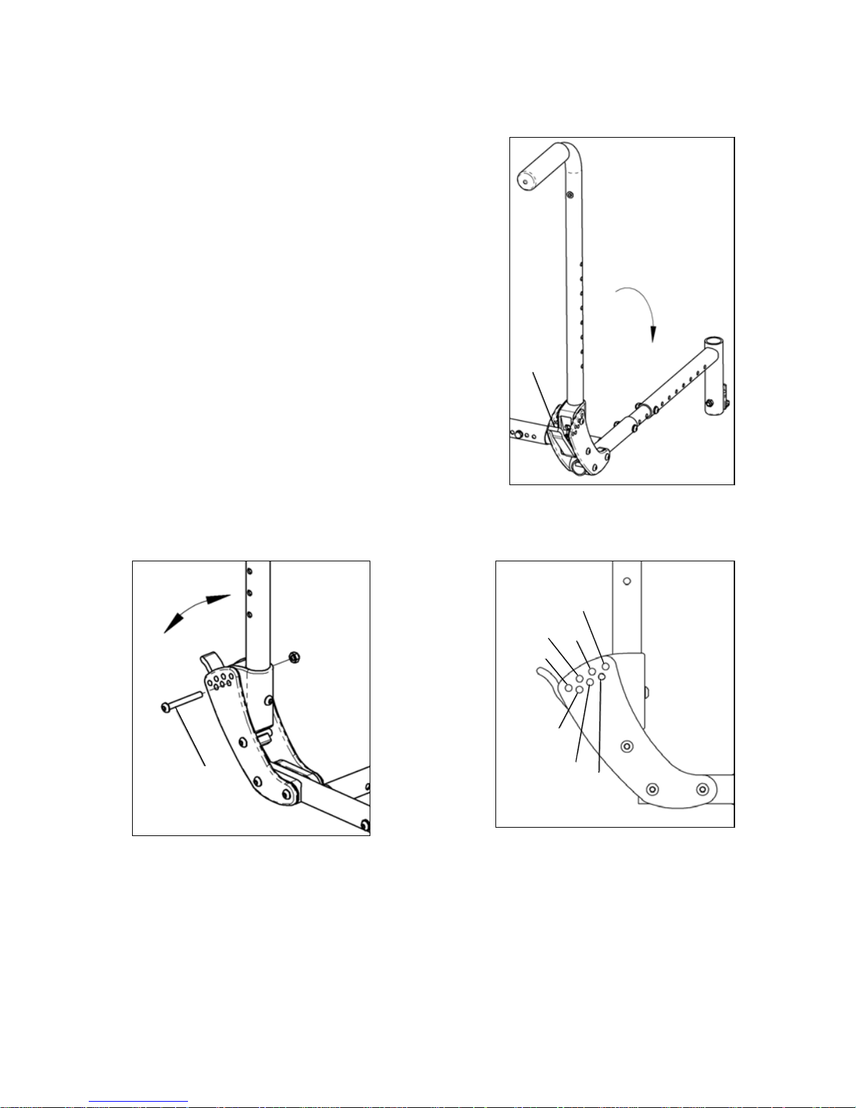
1. Flipping Anti-Tips Up
a. Pull anti-tip (Fig. 48:A) rearward to disengage rotary lock studs (Fig. 48:B).
b. Rotate anti-tip upwards.
c. Reset anti-tip back onto rotary lock studs, ensuring studs are nested into alignment slots.
2. Removing Anti-Tips
a. Depress buttons (Fig. 48:C) on anti-tips.
b. Pull anti-tip straight back to remove anti-tip from receiver.
c. To reinstall, press buttons in and push anti-tips back into receivers, aligning holes in receiver
with front detent button.
3. Setting for Seat Height
a. Using a 4mm Allen wrench and a 10mm wrench, remove cross bolt (Fig. 48:D) from height
adjuster (Fig. 48:E).
b. Slide height adjuster up or down as necessary, aligning holes in adjuster with hole in anti-tip.
The distance between the bottom of the anti-tip wheel and the floor should be between 1.5"
and 2".
c. Reinstall cross bolt through height adjuster and tighten.
d. Repeat for opposite side of chair. Ensure anti-tips on both sides of chair are set up identi-
cally.
Fig. 48
A
B
C
E
D
Page 44

43
V. SET UP & USE OF YOUR WHEELCHAIR
W. Seat Pan
1. Removal
a. Using a 5mm Allen wrench, remove button head
screws (Fig. 49:A) from corners of seat pan.
b. Remove seat pan assembly (Fig. 49:B), seat pan
brackets (Fig. 49:C), seat pan clamps (Fig. 49:D)
and nuts (Fig. 49:E) from seat tubes.
2. Installation
a. Set seat pan onto seat frame.
b. Slide one seat pan bracket (Fig. 49:C) onto seat
tube and link seat pan clamp (Fig. 49:D) onto
bracket, wrapping around seat tube. Hold nut
(Fig. 49:E) in slot of clamp as shown and thread
button head screw (Fig. 49:A) through seat pan
into clamp. Do not tighten. Repeat for all four corners of seat pan.
c. Adjust seat pan in so it is square to the chair and in the desired position, with the front edge
of the seat pan approximately 3/8" behind vertical footrest hanger tube.
d. Tighten all four button head screws using a 5mm Allen wrench when proper position is
obtained.
3. Length Adjustment
a. Using a 5mm Allen wrench and a 13mm wrench, remove all four button head screws (Fig.
49:F) from center area of seat pan.
b. With 5mm Allen wrench, loosen all four button head screws (Fig. 49:A) from seat pan
clamps (Fig. 49:C).
c. Slide seat pans forward or rearward, aligning proper holes to achieve desired seat pan
length.
d. Reinstall and tighten button head screws (Fig. 49:F) with nuts.
e. Reposition seat pan on seat frame as necessary and tighten button head screws (Fig. 49:A)
in clamps.
4. Width Adjustment
NOTE: Seat pan width may be adjusted up to 2" wider for even widths or 1" wider for odd
widths. For greater adjustment than this, new seat pans must be obtained. Contact Ki Mobility
Customer Service.
a. Remove seat pan (See step 1 above) and adjust width of chair to desired width (See Section
U).
b. Align seat pan clamp holes with desired set of holes in seat pan to achieve larger frame
width.
c. Reinstall and tighten button head screws and nuts through seat pan clamps (See step 2
above).
A
B
C
D
E
F
Fig. 49
Page 45

44
V. SET UP & USE OF YOUR WHEELCHAIR
X. Bearings
1. Bearing Replacement (it is recommended this
procedure be performed by a qualified technician)
a. Using a 17mm wrench and a 6mm Allen wrench,
loosen and remove all four bearing locknuts (Fig.
50:A).
b. Remove flat head screws (Fig. 50:B and C) from
bearing subassemblies.
c. Remove all bearing assembly components from
chair.
d. Using new bearing/liners (Fig. 50:D), slide bearing
shaft (Fig. 50:E) through one bearing/liner subassembly as shown.
e. Place shaft with bearing/liner through slot in
rotary frame from the outside and slide spacer
(Fig. 50:F) and second bearing/liner over shaft.
"Noses" of bearing liners should face each other.
f. Align bearing shaft hole with hole in front bearing plate of base frame (Fig. 50:G) and slide
10mm x 50mm (Fig. 50:B) flat head screw through shaft.
g. Install washers (Fig. 50:H) and locknut (Fig. 50:A) back onto flat head screw, finger tight.
h. Repeat steps d through g for opposite side of chair.
i. Install bearing shaft through bores of two more bearings with spacer (Fig. 50:F) in between,
as in step e above.
j. Slide onto 10mm x 60mm (Fig. 50:C) flat head screw through rear bearing plate holes (Fig.
50:I) as shown. Repeat on opposite side of chair.
k. Set rotary frame on both sets of bearings, placing ridge in bottom of rotary frame into
groove between bearing liners. Install swivel bushing (Fig. 50:J) with flange toward bearing
and slide swivel plate (Fig. 50:K) over swivel bushing with retainer bearing nested in inside
groove of rotary frame. Secure with washer (Fig. 50:E) and lock nut (Fig. 50:A). Repeat for
opposite side of chair.
Fig. 50
A
A
B
C
D
D
D
E
E
F
F
G
H
H
I
J
K
Page 46

45
V. SET UP & USE OF YOUR WHEELCHAIR
Y. Vent and Battery Tray
1. Instructions for Use:
Consult your authorized Ki Mobility supplier to ensure the vent and battery tray are appropriate for
the devices being secured to them.
Adjustments to the vent and battery tray should only be done by an authorized Ki Mobility supplier.
2. Instructions for Transit Use:
When using this wheelchair as a seat in a motor vehicle you must remove any items attached to
the vent and battery tray and properly secure them separately. Only authorized dealers should
install, remove or adjust the vent and battery tray components.
DANGER: Failure to remove items attached to the vent and battery tray and properly secure
them separately in the motor vehicle can result in these items becoming dangerous projectiles in
the event of an accident. This can cause severe injury or death.
Z. Oxygen Tank Holder
1. Instructions for Use:
This oxygen tank holder has been designed to secure D cylinders to your wheelchair. Make sure
that the bottle is well seated in the bottom of the holder and that the clamp is tightened to the
point that the cylinder cannot be pulled out.
Oxygen tanks can be dangerous, make sure you follow all instructions for use from the tank’s
provider.
DANGER: Failure to follow these instructions and the instructions for use of the cylinder from the
cylinder’s provider can result in severe injury or death.
Page 47

46
VI. MAINTENANCE
A. Inspecting Your Wheelchair
Regular and routine maintenance will extend the life of your wheelchair while improving its
performance. Wheelchair repairs and the replacement of parts should be done by a qualified
technician of an authorized Ki Mobility supplier.
1. General Inspections:
a. Clean your chair at least once per month. You may need to clean your chair more frequently
if you operate it in dirty environments, such as a worksite.
b. Check to be sure that all fasteners are tight. Unless otherwise noted, fasteners should be
tightened to 40 in./lbs.
c. Check tires and casters:
• Check the tire for tread wear. Replace the tires if they have flat spots, visible cracks or
if the tread is worn off.
• If you have inflatable tires with a valve stem, check the pressure and set to the
pressure listed on the tire sidewall.
DANGER: Replace worn tires. The wheel locks will not grip properly if you fail to maintain the air
pressure shown on tire sidewall. This could result in a fall or loss of control and cause severe injury
or death.
d. Check spoke wheels for loose spokes.
e. Check your wheel locks. As tires wear the wheel locks should be adjusted. See Section S.
Wheel Locks.
Page 48

47
VI. MAINTENANCE
B. Routine Maintenance
1. Weekly:
a. Check wheel locks to be sure they are adjusted correctly.
b. Check axle sleeves to ensure the axle sleeve nuts are tight.
c. Check for broken, bent or loose spokes.
d. Check that casters spin freely.
e. Inspect tires and casters for wear spots.
f. Check pneumatic tires for proper inflation.
g. Wipe rotary frame glide surfaces with a damp cloth.
h. Adjust tilt cable to ensure proper tilt lock function (See Section V., Part N Step 1:B or 2:B).
i. Inspect roller bearings to ensure proper function and wear.
2. Monthly:
a. Inspect rear wheel axles and tighten if necessary.
b. Inspect caster housing bearings for hair build up and remove if necessary.
c. Inspect wheel locks to be sure assembly is tight. Make sure wheel locks properly engage
the tires.
d. Check that all fasteners are tight and secure.
e. Inspect hand grips to ensure they are not loose.
f. Inspect frame for any deformities, defects, cracks, dimples or bends. These could be signs
of fatigue in the frame which could result in a failure of the chair. Discontinue use of the
wheelchair immediately and contact your authorized Ki Mobility dealer.
3. Annually:
a. Have wheelchair checked and adjusted by a qualified technician.
WARNING: After adjustments and before using this wheelchair, make sure that all of the
fasteners are tight and secure or injury or damage may occur.
CAUTION: Do not overtighten fasteners as this could damage the frame tubing.
DANGER: Failure to read and comply with these instructions may result in a fall or loss of control
causing severe injury or death to the user or others.
Page 49

48
VI. MAINTENANCE
C. Cleaning
1. Axles and Wheels:
a. Clean around the axles and wheels WEEKLY with a damp rag.
b. Hair and lint will lodge in the caster housing. Disassemble the caster housing every six
months to remove entangled hair.
NOTE: Do not use WD-40 or any other penetrating oil on this wheelchair. This will destroy the
sealed bearings.
NOTE: Do not use any chemical cleaning agents on casters or tires.
WARNING: Failure to read and comply with these instructions may result in damage to your
wheelchair, a fall or loss of control causing severe injury to the user or others.
D. Storage
1. When not in use, keep your chair in a clean, dry area. Failure to do so may result in your chair
rusting and/or corroding.
2. If your chair has been in storage for more than a few weeks you should make sure it is working
properly. You should inspect and service, if necessary, all items in Section A. Inspecting Your
Wheelchair.
3. If your chair has been in storage for more than two months, it should be serviced and
inspected by your authorized supplier before you use it.
WARNING: Failure to read and comply with these instructions may result in damage to your
wheelchair, a fall, or loss of control causing severe injury to the user or others.
Page 50

49
VII. TROUBLESHOOTING
A. Symptoms and Solutions
For optimum performance, your Focus CR wheelchair will need to be adjusted occasionally. On
the next page is a list of potential symptoms that may occur when adjusting your chair, as well as
one or more suggested solutions for each symptom. For best results, when troubleshooting, try
one solution at a time before proceeding to a second solution. If symptoms are not relieved, it is
recommended to take the chair to an authorized service center for repair.
Please see chart on next page.
Page 51

50
Chair does
not track
straight
Looseness
in chair
Sluggishness
in turning
One caster
does not
contact the
floor
Caster
flutters
Squeaking
or rattling
Will not tilt/
Rattles
when tilting
Difficulty
in tilting
Chair tilts
too quickly
and is
difficult to
recover
Chair is
difficult to tilt
and
recovers
too quickly
Add spacer washer between caster
stem and bottom caster housing bearing
on left or right side of chair.
Ensure all tire pressures are correct and
equal on both sides of chair.
Ensure all fasteners ar e tightened .
Use Teflon® based lubricant (such as Tri-
Flow®) between modular frame
components.
Ensure cable/foot tilt mechanism is
adjusted and cogs disengage teeth (see
section V. N. 1. b or V. N. 2. b).
Inspect roller bearings for wear. Replace
if necessary (see section V. X).
Inspect rotary frame bearing surfaces for
damage. Clean as necessary.
Optimize CG setting (Section V. O. 2).
Symptoms
Solutions
Page 52

51
VIII. WARRANTY
A. Warranty Information
Ki Mobility warrants the frame, hangers, tilt assembly (including bearings) and quick-release axles
of this wheelchair against defects in materials and workmanship for the life of the original
purchaser. All other Ki Mobility-made parts and components of this wheelchair are warranted
against defects in materials and workmanship for one year from the date of first consumer
purchase.
The expected life of the frame is five years.
Limitations to the Warranty
1. We do not warrant:
a. Wear items: Upholstery, tires, armrest pads, tubes, armrests and push-handle grips.
b. Damage resulting from neglect, misuse or from improper installation or repair.
c. Damage from exceeding weight limit.
2. This warranty is VOID if the original chair serial number tag is removed or altered.
3. This warranty is VOID if the original chair has been modified from its original condition and it is
determined the modification resulted in failure.
4. This warranty applies in the USA only. Check with your supplier to find out if international
warranties apply.
Ki Mobility’s Responsibility
Ki Mobility’s only liability is to replace or repair, at our discretion, the covered parts. There are no
other remedies, expressed or implied.
Your Responsibility
a. Notify Ki Mobility, via an authorized supplier, prior to the end of the warranty period and get
a return authorization (RA) for the return or repair of the covered parts.
b. Have the supplier send the authorized return, freight pre-paid, to:
Ki Mobility
5201 Woodward Drive
Stevens Point, WI 54481
c. Pay any charges for labor to repair or install parts.
Page 53

Page 54

53
Gracias por comprar una silla de ruedas Focus CR!
Por favor, no use esta silla de ruedas sin antes leer completamente este manual.
ANTES de conducir, debe estar capacitado en el uso seguro de esta silla por un
practicante de Tecnología Asistencial (ATP) o profesional clínico.
Si usted tiene alguna pregunta o inquietud acerca de cualquier aspecto de esta silla de
ruedas, en este manual, o el servicio prestado por Ki Mobility o su proveedor minorista,
por favor no dude en ponerse en contacto con nosotros por teléfono al:
715-254-0991
Por escrito a:
Ki Mobility
5201 Woodward Drive
Stevens Point, WI 54481
U.S.A
O por correo electrónico a:
sales@kimobility.com
O a través de nuestro Representante EU Autorizado:
James Leckey Design
19C Ballinderry Road
Lisburn
BT28 2SA
Phone: 0800 318265 (UK) or 1800 626020 (ROI)
www.leckey.com
I. INTRODUCCIÓN
Page 55

54
I. INTRODUCCIÓN
II. TABLA DE CONTENIDOS
III. AVISO - LEA ANTES DE USAR
A. Su Seguridad y Estabilidad ................................................................. 56
IV. ADVERTENCIAS
A. Palabras de Advertencia ..................................................................... 56
B. Advertencias Generales....................................................................... 57
C. Cinturones de Posicionamiento........................................................... 58
D. Andar en Silla de Ruedas .................................................................... 59
E. Motores .............................................................................................. 60
F. Ascender Escaleras............................................................................. 60
G. Descender Escaleras .......................................................................... 60
H. Transferencias..................................................................................... 61
I. Su Silla de Ruedas y el Medio Ambiente ............................................. 61
J. Modificación de su Silla de Ruedas ..................................................... 62
K. Estabilidad en su Silla de Ruedas........................................................ 62
V. CONFIGURACIÓN Y USO
A. Su Focus CR y Sus Partes.................................................................. 65
B. Uso Tránsito........................................................................................ 66
C. Brazos-T de Altura Ajustable............................................................... 69
D. Reposabrazos Giratorio de Poste Doble Altura Ajustable..................... 71
E. Apoyabrazos Extendido Flip Up con Angulo Ajustable Bloqueable ...... 72
F. Advertencias de Reposabrazos........................................................... 72
G. Sostenes Giratorios............................................................................. 73
H. Apoyapiernas Swing Away con Pestillo de 4 Posiciones...................... 74
I. Tubos de Extensión ............................................................................ 75
J. Elevar Reposapiernas.......................................................................... 76
K. Apoyapiernas Elevable Pro.................................................................. 77
L. Respaldo ............................................................................................ 78
M. Respaldo Reclinable............................................................................ 80
N. Mecanismo de Inclinación................................................................... 83
O. Configuración del Bastidor del Asiento................................................ 85
P. Ruedas Pivotantes .............................................................................. 86
Q. Placa del Eje ....................................................................................... 87
R. Ruedas Traseras ................................................................................. 89
S. Seguros de las Ruedas ....................................................................... 90
T. Freno de Tambor ................................................................................ 92
U. Anchura del Marco.............................................................................. 93
V. Tubos Contra Volcaduras.................................................................... 94
II. TABLA DE CONTENIDOS
Page 56

55
W. Recipiente del Asiento......................................................................... 95
X. Rodamientos....................................................................................... 96
Y. Respiradero y la Bandeja de la Batería................................................ 97
Z. Tanque de Oxigeno............................................................................. 97
VI. MANTENIMIENTO
A. Inspección de la Silla de Ruedas......................................................... 98
B. Mantenimiento de Rutina .................................................................... 99
C. Limpieza ............................................................................................ 100
D. Almacenamiento ................................................................................ 100
VII. SOLUCIÓN DE PROBLEMAS ................................................................... 101
VIII. GARANTÍA ................................................................................................. 103
II. TABLA DE CONTENIDOS
Page 57

56
III. AVISO - LEA ANTES DE USAR
A. Su Seguridad y Estabilidad
Ki Mobility fabrica muchas sillas diferentes que pueden satisfacer sus necesidades. Debe
consultar con un Profesional de Asistencia Tecnologíca al seleccionar el modelo que mejor se
adapta a sus necesidades particulares y la forma en que la silla de ruedas se debe instalar y
ajustar. La selección final del tipo de silla de ruedas, las opciones y ajustes corresponde
únicamente en usted y su profesional médico. Las opciones que elija, la instalación y el ajuste de
la silla de ruedas tienen un impacto directo en su estabilidad. Los factores a considerar que
afectan su seguridad y la estabilidad son:
a. Sus habilidades y capacidades, incluyendo fuerza, equilibrio y coordinación personal.
b. Los tipos de peligros y obstáculos que pueden surgir durante el día.
c. Las dimensiones especifícas, opciones y configuración. En particular, la altura del asiento,
la profundidad del asiento, ángulo del asiento, ángulo del respaldo, el tamaño y la posición
de las ruedas traseras y el tamaño y la posición de las ruedas pivotantes. Cualquier
cambio en cualquiera de estos elementos va a cambiar la estabilidad de la silla de ruedas.
Sólo debe hacer cambios después de consultar con un profesional calificado.
IV. ADVERTENCIAS
A. Palabras de Advertencia
En este manual se incluye lo que se conoce como palabras “Señal”. Estas palabras se usan para
identificar y transmitir la gravedad de los diferentes riesgos. Antes de usar esta silla de ruedas,
usted y cada persona que pueda ayudarle, debe leer todo el manual. Por favor, tenga en cuenta
las palabras de advertencia y considere las advertencias, precausiones y peligros. Asegúrese de
seguir todas las instrucciones y usar su silla de ruedas con seguridad. La Palabra de advertencia
indica un riesgo o uso peligroso que puede provocar lesiones graves o la muerte de usted o otras
personas. Las “Advertencias” se dividen en tres categorías principales, de la siguiente manera:
PELIGRO – Peligro indica una situación inminentemente peligrosa que, de no evitarse, puede
ocasionar lesiones graves o la muerte.
ADVERTENCIA – Advertencia indica una situación potencialmente peligrosa que, de no evitarse,
puede ocasionar lesiones graves o la muerte.
PRECAUSIÓN – Precausión indica una situación potencialmente peligrosa que, de no evitarse,
puede provocar lesiones o daños a la silla de ruedas.
Estas palabras de señalización se colocarán a lo largo del manual, en su caso, para resaltar la
situación de peligro. Consulte la siguiente lista para situaciones peligrosas que se aplicarán en la
utilización general de esta silla de ruedas.
Page 58

57
IV. ADVERTENCIAS
B. Advertencias Generales
ADVERTENCIA: NO exceda la capacidad máxima de peso de 136 kg en el cuadro estandar, ó
de 182 kg en un cuadro Heavy Duty. Revise la etiqueta del número de serie para conocer la
capacidad máxima de peso de la silla. Este es el peso combinado del usuario y todos los
objetos que lleven consigo. Exceder el límite de peso puede causar daño a su silla o aumentar la
probabilidad de una caída o volcadura hacia atrás y causar lesiones graves o la muerte para el
usuario o para otros.
PELIGRO: No use esta silla para el entrenamiento con pesas. El movimiento del peso
adicional alterará el centro de gravedad de la silla de ruedas que aumenta la probabilidad de un
vuelco, que puede causar daño a su silla o causar lesiones graves o la muerte para el usuario o
los demás.
ADVERTENCIA: Si su silla está equipada con neumáticos inflables, asegúrese de que los
neumáticos hayan sido inflados a la presión correcta de los neumáticos como se indica en la
pared lateral del neumático. Su proveedor de silla de ruedas puede determinar si usted tiene
neumáticos inflables. El uso de la silla de ruedas sin neumáticos inflados correctamente puede
tener un efecto en la estabilidad de la silla de ruedas haciendo que se vuelque con resultado de
muerte o lesiones al usuario o a otras personas.
PELIGRO: No trate de empujar su silla de ruedas hacia arriba o bajo rampas o recorrer a
través de un pendiente de más de 9 grados. Esto es peligroso y aumenta la probabilidad de una
caída o volcadura hacia atrás y causar lesiones graves o la muerte para el usuario o para otros.
ADVERTENCIA: No trate de empujar su silla de ruedas por una pendiente que es liso o
cubierto con hielo, aceite o agua. Esto puede causar una situación inestable que resulta en la
muerte o lesiones al usuario o a otras personas.
ADVERTENCIA: No se incline sobre la parte lateral o posterior de la silla de ruedas para
ampliar su alcance. Esto puede ocasionar que cayera de la silla, o que la silla de ruedas pueda
volcarse y causar lesiones o la muerte.
Page 59

58
IV. ADVERTENCIAS
B. Advertencias Generales
PELIGRO: No intente levantar la silla de ruedas aferrandose a las piezas desmontables,
como los brazos o los reposapiés. Sólo levante la silla aferrandose al marco. Esto puede
provocar una caída o pérdida del control y provocar lesiones graves o la muerte.
PRECAUSIÓN: No apriete demasiado los tornillos y hardware que conecta varios componentes juntos en el marco. Esto podría causar daños graves y afectar la seguridad y la durabilidad de
la silla de ruedas.
C. Cinturones de Posicionamiento
Los cinturones de posicionamiento, están diseñados para ayudar en la colocación apropiada
dentro de la silla de ruedas. No están diseñados como cinturones de seguridad. Use el cinturón
de posicionamiento SOLAMENTE para ayudar a apoyar la postura del usuario. El mal uso de los
cinturones de posicionamiento puede causar lesiones graves o la muerte del usuario.
• Asegúrese de que el usuario no se deslize por debajo del cinturón de posición en el
asiento de la silla de ruedas. Si esto ocurre, la respiración del usuario puede verse
obstaculizado y causar la muerte o lesiones graves.
• El cinturón de posicionamiento debe tener un ajuste perfecto; apretado lo suficiente para
mantener su posición, pero no tan fuerte como para restringir la respiración. Usted debe
ser capaz de deslizar la mano entre el cinturón de posicionamiento y el usuario.
• NUNCA utilice el Cinturón de Posicionamiento:
a. Como un sistema de retención. Un restrictor de movimiento requiere la orden de un
médico.
b. En un usuario que está inconsciente.
c. Como una de retención de ocupantes en un vehículo. Un cinturón de posicionamiento no
está diseñado para reemplazar un cinturón de seguridad que está unido al bastidor de un
vehículo, que se requiere para que un cinturón de seguridad sea efectiva. Durante una
parada repentina, con la fuerza de la parada, el usuario será arrojado hacia adelante. Cinturones de seguridad para sillas de ruedas no prevendrán esto y más lesiones pueden
resultar de los cinturones o correas.
Vea Uso Tránsito (V. CONFIGURACIÓN Y USO, Sec-
ción B).
PELIGRO: El incumplimiento de las instrucciones anteriores puede resultar en lesiones
graves o la muerte.
Page 60

59
IV. ADVERTENCIAS
D. Andar en Silla de Ruedas
Su silla está diseñada para su uso en superficies sólidas, planas, tal como concreto, asfalto y
suelos. Tenga cuidado si usted empuja su silla de ruedas en una superficie mojada o
resbaladiza.
ADVERTENCIA: No empuje su silla en arena, tierra suelta o sobre terreno áspero. Esto puede
causar una pérdida de estabilidad y provocar una caída o pérdida del control y provocar
lesiones graves o la muerte.
PELIGRO: En la mayoría de los estados, las sillas de ruedas no son legales para su uso en la
vía pública. Si usted encuentra que usted tiene que empujar en la vía pública, esté alerta
sobre el peligro de los vehículos. El uso de una silla de ruedas en la vía pública puede causar
lesiones graves o la muerte.
ADVERTENCIA: Los obstáculos y los peligros del camino (como baches y pavimento roto)
pueden dañar su silla y pueden causar una caída, un vuelco o pérdida de control. No cumplir
con estas instrucciones podría resultar en lesiones graves o la muerte.
PELIGRO: No use su silla de ruedas en una escalera mecánica. El uso de una silla de ruedas en
una escalera mecánica puede causar lesiones graves o la muerte.
Para minimizar estos riesgos:
1) Mantenga un puesto de observación para el peligro - escanea el área mucho antes de
que su silla pase.
2) Asegúrese de que los pisos donde usted vive y trabaja estén a nivel y sin obstáculos.
3) Retira o cubra las tiras de los umbrales entre las habitaciones.
4) Instale una rampa en las puertas de entrada o salida. Asegúrese de que no hay una
caída en la parte inferior de la rampa.
5) Para Ayudar a Corregir su Centro de Equilibrio:
a. Incline la parte superior del cuerpo ligeramente hacia ADELANTE a medida que
AVANZA a lo largo de un obstáculo.
b. Presione la parte superior del cuerpo hacia ATRÁS a medida que AVANZA por
debajo de un nivel superior a uno inferior.
6) Si su silla tiene tubos contra volcaduras, colocarlos en su sitio antes de ir a lo largo de
un obstáculo.
7) Mantenga ambas manos sobre los aros de empuje a medida que avanza sobre un
obstáculo.
8) Nunca empuje o jale de un objeto (como muebles o una jamba de la puerta) para propulsar su silla.
9) No haga funcionar su silla de ruedas en las carreteras o calles.
10) No trate de empujar por encima de obstáculos sin ayuda.
Page 61

60
IV. ADVERTENCIAS
E. Motores
Ki Mobility no recomienda la instalación de sistemas de motores en cualquier silla de ruedas
Focus CR.
Sillas de ruedas Focus CR no han sido diseñadas o probadas como sillas de ruedas eléctricas. Si
se agrega un sistema de motor de potencia a una silla de ruedas Focus CR, asegúrese de que el
fabricante del sistema de motor de potencia se ha validado y aprobado la combinación del
sistema de motor de potencia y su silla de ruedas Focus CR como seguro y eficaz.
ADVERTENCIA: El uso de un sistema de motor que no ha sido validado adecuadamente
podría causar lesiones graves o la muerte.
F. Ascender Escaleras
• Tener por lo menos dos personas, que tengan fuerza y habilidad suficiente para
soportar el peso del usuario y la silla de ruedas, ayudar cuando se trata de subir un
tramo de escaleras en esta silla de ruedas.
• Mueva la silla de ruedas y el usuario hacia atrás por las escaleras.
• Una persona detrás del usuario, y una persona adelante. La persona frente debe
mantenerse en una parte inamovible de la silla de ruedas.
• El encargado de la parte trasera se inclina la silla hacia atrás y ambos levantan juntos.
Dando un paso a la vez.
• Esto puede requerir que los tubos contra volcaduras sean volteados hacia arriba o
retirados. Verifique que los tubos contra volcaduras se vuelven a unir o volteadas hacia
abajo antes de usar la silla de ruedas.
PELIGRO: El incumplimiento de las instrucciones anteriores puede resultar en lesiones
graves o la muerte.
G. Descender Escaleras
• Al descender por unas escaleras el usuario debe estar mirando hacia adelante.
• Una persona detrás del usuario, que tenga suficiente fuerza y habilidad para manejar el
peso del usuario y la silla de ruedas, debe inclinar la silla hacia atrás y dejar que baje la
silla por las escaleras un paso a la vez en las ruedas traseras.
• Esto puede requerir que los tubos contra volcaduras sean volteados hacia arriba o
retirados. Verifique que los tubos contra volcaduras se vuelven a unir o volteadas hacia
abajo antes de usar la silla de ruedas.
PELIGRO: El incumplimiento de las instrucciones anteriores puede resultar en lesiones
graves o la muerte.
Page 62

61
IV. ADVERTENCIAS
H. Transferencias
Una transferencia requiere buen equilibrio y estabilidad. Usted debe recibir entrenamiento de su
terapeuta antes de intentar hacer una transferencia por su cuenta.
• Antes de transferir fuera de su silla de ruedas se debe tener cuidado para reducir el
espacio entre las dos superficies.
• Emplear los frenos de las ruedas para bloquear las ruedas traseras.
• Gire las ruedas pivotantes hacia adelante para aumentar la distancia entre ejes de la silla
de ruedas.
• Retire o abatir los reposapiés.
• Consiga que alguen lo asista al menos que tenga mucha experiencia en las transferencias.
Es peligroso transferirse usted solo. Se requiere de buen equilibrio y agilidad. Tenga en cuenta
que hay un punto en cada transferencia en que el asiento de la silla de ruedas no esta por debajo
de usted.
ADVERTENCIA: Si no se realiza una transferencia adecuada puede dar lugar a una caída y
puede causar lesiones graves o la muerte.
I. Su Silla de Ruedas y el Medio Ambiente
• Su silla de ruedas está hecha de muchos materiales diferentes, incluyendo metal y tela. La
exposición al agua o humedad excesiva puede hacer que el metal en la silla de ruedas se
oxide y la tela se rasgué. Seque la silla tan pronto como sea posible si se expone al agua.
• NO UTILICE LA SILLA DE RUEDAS EN UNA DUCHA, ALBERCA O CUERPO DE AGUA.
Esto hará que su silla de ruedas se oxide o corroe y eventualmente falle.
• No utilice su silla de ruedas en la arena. La arena puede entrar en los valeros de las ruedas
y partes móviles. Esto puede causar daños y, finalmente, hará que la silla de ruedas falle.
• Asegúrese de que cualquier rampa, pendiente o bordillo que pueda intentar montar
cumpla con las directrices de la ADA. El montar a través, hacia arriba o hacia abajo de
cualquier pendiente que es demasiado grande puede causar una pérdida de estabilidad.
Lineamientos de ADA y más información sobre el diseño accesible están disponibles en
http://www.ada.gov/
ADVERTENCIA: El incumplimiento de las instrucciones anteriores puede provocar una caída
o pérdida del control, lo que puede provocar lesiones graves o la muerte.
Page 63

62
IV. ADVERTENCIAS
J. Modificación de su Silla de Ruedas
La silla de ruedas se ha diseñado y fabricado bajo los estrictos controles de diseño. Una parte
integral de este proceso es asegurar que los diversos componentes trabajen juntos
correctamente, que han sido probados en distintas normas para garantizar la calidad y están
aprobados para trabajar juntos.
NADIE DEBE MODIFICAR ESTA SILLA DE RUEDAS CON EXCEPCIÓN DE MONTAJE DE
OPCIONES APROBADOS. NO HAY OPCIONES APROBADOS QUE IMPLICAN REALIZAR
ORIFICIOS O CORTES EN EL MARCO POR CUALQUIERA QUE NO SEA UN ASOCIADO DE
KI MOBILITY ENTRENADO. Contacto con Ki Mobility o un proveedor autorizado de Ki
Mobility antes de añadir accesorios o componentes no proporcionados por Ki Mobility.
PELIGRO: El incumplimiento de estas instrucciones puede causar que la silla de ruedas
pueda fallar y provocar lesiones graves o la muerte.
K. Estabilidad en su Silla de Ruedas
Para asegurar la estabilidad adecuada de la silla de ruedas se debe asegurar el centro de
gravedad y la base de la silla de ruedas de apoyo es correcta para su equilibrio y habilidades. Hay
muchos factores que pueden afectar a estos dos elementos;
En general, el factor más importante es la posición de las ruedas traseras para la estabilidad
posterior. Hay otras acciones que puedan tener un efecto adverso en su estabilidad. Usted debe
consultar con su proveedor de sillas de ruedas y los médicos que están familiarizados con sus
necesidades y capacidades en la determinación de cómo esto afectan a su uso.
ADVERTENCIA: Moviendo las ruedas traseras hacia adelante aumenta la probabilidad de que
la silla de ruedas se vuelque hacia atrás. Haga pequeños ajustes y proceda lentamente hasta
que aprenda el nuevo punto de equilibrio de su silla de ruedas. El incumplimiento de las
instrucciones anteriores puede resultar en lesiones graves o la muerte.
ADVERTENCIA: Cuanto más atrás se coloca la rueda pivotante mayor es la probabilidad de
que la silla de ruedas se vuelque hacia adelante. Si es posible, haga que sus ruedas pivotantes
sean montadas hacia adelante y, cada vez que hace una actividad estática que implica
desplazar el peso, gire las ruedas hacia adelante para aumentar su distancia entre ejes. El
incumplimiento de las instrucciones anteriores puede resultar en lesiones graves o la muerte.
• Altura del asiento
• Profundidad del asiento
• Ángulo del respaldo
• El tamaño y la posición de las ruedas traseras
• El tamaño y la posición de las ruedas pivotantes
• Cualquier componente del sistema de asientos
Page 64

63
IV. ADVERTENCIAS
K. Estabilidad en su Silla de Ruedas
ADVERTENCIA: Siempre tenga a un técnico calificado configurar su silla de ruedas con los
accesorios que va a utilizar todos los días.
ADVERTENCIA: Los cambios en la forma en que usted se sienta o cambios en su peso
requieren que su silla sea ajustada por un técnico calificado. Siempre use tubos contra
volcaduras mientras se aclimata a los cambios en su silla de ruedas. El incumplimiento de las
instrucciones anteriores puede resultar en lesiones graves o la muerte.
ADVERTENCIA: Cambios en su Centro de Gravedad durante sus actividades diarias pueden
ocurrir varias veces al día y cambiar y afectar la estabilidad de la silla de ruedas. Usted debe
ser consciente de estas actividades y tomar las precauciones para minimizar el riesgo de una
caída. El incumplimiento de las instrucciones anteriores puede resultar en lesiones graves o la
muerte.
ADVERTENCIA: Vestirse en su silla de ruedas produce movimientos y posiciones
momentáneas que pueden reducir la estabilidad. Asegurarse de que sus tubos contra
volcaduras están en su lugar y rotar sus ruedas pivotantes hacia adelante. El incumplimiento
de las instrucciones anteriores puede resultar en lesiones graves o la muerte.
ADVERTENCIA: Tenga mucho cuidado cuando trate de alcanzar objetos si este movimiento
requiere que se cambie en su asiento. Esto cambia el centro de gravedad. Asegurarse de que
sus tubos contra volcaduras están en su lugar. El incumplimiento de las instrucciones
anteriores puede resultar en lesiones graves o la muerte.
ADVERTENCIA: Empujando por una pendiente desplaza su centro de gravedad hacia atrás y
puede reducir la estabilidad. Asegurarse de que sus tubos contra volcaduras están en su lugar.
El incumplimiento de las instrucciones anteriores puede resultar en lesiones graves o la muerte.
ADVERTENCIA: Si intenta un caballito para superar un bordillo o obstáculo, procure que los
tubos contra volcaduras están en su lugar y se inclina hacia adelante. No intente un caballito
al menos que haya sido entrenado y siempre tenga un asistente detrás de usted para
proporcionar ayuda si es necesario. El incumplimiento de las instrucciones anteriores puede
resultar en lesiones graves o la muerte.
Page 65

64
IV. ADVERTENCIAS
K. Estabilidad en su Silla de Ruedas
ADVERTENCIA: La colocación de artículos en la parte trasera o delantera de su silla de ruedas,
como una mochila o maletín, altera el equilibrio y el centro de gravedad de la silla de ruedas.
Dado que el peso de estos artículos puede variar mucho en cada uso, no asuma que está
acostumbrado al punto de equilibrio. El incumplimiento de las instrucciones anteriores puede
resultar en lesiones graves o la muerte.
TENGA EN CUENTA QUE LLEVA OBJETOS PESADOS SOBRE LA SILLA DE RUEDAS QUE
PUEDE TENER UN EFECTO ADVERSO SOBRE SU BALANCE QUE PUEDE CAUSAR UN
VUELCO Y RESULTE EN LESIONES GRAVES O LA MUERTE DEL USUARIO.
ADVERTENCIA: Asegúrese de que sus tubos contra volcaduras están en su lugar. Usted
debe discutir cómo va a utilizar su silla de ruedas o cualquier cambio que se está planeando
con su médico. El incumplimiento de esta instrucción puede crear una situación
potencialmente peligrosa que, de no evitarse, puede ocasionar lesiones graves o la muerte.
Page 66

65
V. CONFIGURACIÓN Y USO
A. Su Focus CR y Sus Partes
1. Inspeccione y mantenga esta silla estrictamente por tabla de mantenimiento en la Sección VI.
2. Si detecta algún problema, asegúrese de dar servicio o reparar la silla antes de su uso.
3. Tener una inspección completa, control de seguridad y el servicio de la silla realizada
por un proveedor autorizado anualmente.
ADVERTENCIA: La falta de lectura o el incumplimiento de estas instrucciones puede resultar
en daños a su silla de ruedas, una caída o pérdida del control y provocar lesiones severas al
usuario o a otras personas.
1. Tubo de la Base
2. Bastidor Giratorio
3. Tubo del Asiento
4. Brazo de Rueda Pivotante
5. Poste Posterior
6. Manija de Empuje
7. Gatillo Seguro de Inclinación
8. Cable de Inclinación
9. Clavija de Gatillo Seguro
10. Ruedas Traseras
11. Eje de de Liberación Rápida
12. Tubo Contra Volcadura
13. Seguro de Rueda
14. Horquilla de la Rueda Pivotante
15. Rueda Pivotante
16. Sostenes Giratorios
17. Reposapiés
18. Palanca de Pivote
19. Placa del Eje
20. Recipiente del Asiento
21. Reposabrazos de Doble Poste
Page 67

66
V. CONFIGURACIÓN Y USO
B. Uso Tránsito
Siempre es más seguro para la transferencia de su silla de ruedas al asiento en un vehículo con
asiento apropiado y cinturones de hombro. Nunca use esta silla de ruedas como asiento en un
vehículo, a menos que ha sido equipada con la Opción de Tránsito.
La silla de ruedas Focus CR equipada con la Opción de Tránsito ha sido probada y aprobada con
RESNA WC-4:2012, Sección 19: Las Sillas de Ruedas utilizadas como asientos en vehículos
de motor y ISO 7176-19:2008 Sillas de ruedas -- Parte 19: Dispositivos de movilidad de
ruedas para su uso como asientos de los vehículos de motor. Normas ISO y RESNA están
diseñadas para probar la integridad estructural de la silla de ruedas como un asiento para su uso
en un vehículo de motor. Estas normas también se han diseñado para crear compatibilidad con
los Sujetadores de Silla de Ruedas y de los Sistemas de Sujeción del Ocupante (WTORS) por sus
siglas en inglés.
No todas las configuraciones de las sillas de ruedas Focus CR son compatibles con la Opción de
Tránsito. Ki Mobility administra la configuración y no ofrece la silla de ruedas Focus CR, excepto
en configuraciones compatibles. Si realiza cambios a su silla de ruedas Focus CR después de que
la reciban, debe comunicarse con su proveedor de silla de ruedas o Ki Mobility para asegurarse
de que es conveniente seguir utilizando su silla de ruedas como asiento en un vehículo de motor.
Asientos aftermarket pueden haber sustituido el asiento original del equipo y apoyo para la
espalda diseñado y probado como parte de la Opción de Tránsito. Su proveedor de silla de
ruedas debe decirle si el asiento es de el equipo original o de asientos de reemplazo aftermarket.
Un sistema completo del marco de la silla, asiento, Sujetadores de Silla de Ruedas y de los
Sistemas de Sujeción del Ocupante y un vehículo de motor equipado adecuadamente, que todos
han cumplido con las normas mencionadas en esta sección, debe estar en su lugar antes de usar
una silla de ruedas Focus CR equipada con el Opción de Tránsito como asiento en un vehículo de
motor.
Cuando se utiliza la silla de ruedas como asiento en un vehículo de motor siempre se debe seguir
las siguientes instrucciones:
• El usuario debe estar en una posición orientada hacia adelante.
• El usuario no debe pesar más de 300 libras (400 libras para Opción de Servicio Pesado).
• Las mochilas y las bolsas deben ser removidas y fijadas por separado en el vehículo. En el
caso de un accidente estos artículos pueden convertirse en proyectiles peligrosos, lo que
puede lesionar o matar a usted o los demás ocupantes del vehículo de motor.
• El usuario debe utilizar Sujetadores de Silla de Ruedas y un Sistema de Sujeción del
Ocupante que cumpla con RESNA WC-4: 2012, Sección 18: Sujetadores de Silla de
Ruedas y Sistemas de Sujeción del Ocupante para su uso en vehículos de motor o ISO
10542-1:2012 Sistemas técnicos y ayudas para las personas con discapacidad o
movilidad reducida - Sujetadores de Silla de Ruedas y Sistemas de Sujeción del
Ocupante -- Parte 1: Requisitos y métodos de pruebas para todos los sistemas.
Fig. 1
Puntos de
Sujeción
Puntos de
Sujeción
Page 68

67
V. CONFIGURACIÓN Y USO
B. Uso Tránsito
• Adjunte sujetadores para sillas de ruedas a los cuatro puntos de sujeción (dos frontales,
dos traseros) en la silla de ruedas Focus CR con la Opción de Tránsito (Fig. 1), de acuerdo
con las instrucciones de la silla de ruedas de sujeción del fabricante y RESNA WC-4:2012,
Sección 18 o ISO 10542-1:2012 - Parte 1.
• Fije las restricciones de los ocupantes de acuerdo con las instrucciones del fabricante de
retención de ocupantes y RESNA WC-4:2012, Sección 18 o ISO 10542-1:2012, Parte 1.
• El uso de cinturones de seguridad, correas para el pecho, arneses de hombro, cualquier
otro sistema de correa de posicionamiento o accesorio de posicionamiento no debe
utilizarse, o confiado como retención del ocupante, a menos que se marque como tal por el
fabricante de acuerdo con RESNA WC-4:2012, Sección 18 o ISO 10542-1:2012, Parte 1.
• El uso de apoyos para la cabeza, soportes laterales o otros accesorios de posicionamiento
no deben utilizarse, o confiado como retención del ocupante, a menos que se marque
como tal por el fabricante de acuerdo con RESNA WC-4:2012, Sección 18 o ISO 10542-
1:2012, Parte 1. o RESNA WC-4:2012, Sección 20: Sistemas de asiento para silla de
ruedas para su uso en vehículos de motor o ISO 16840-4:2009 Asientos para sillas de
ruedas -- Parte 4: Sistemas de asientos para su uso en vehículos de motor.
• Cualquier asiento aftermarket debe ser probado para cumplir con RESNA WC-4:2012,
Sección 20 o ISO 16840-4:2009 - Parte 4.
• Coloque el asiento al marco de silla de ruedas de acuerdo con las instrucciones del
fabricante de asientos y RESNA WC-4:2012, Sección 20 o ISO 16840-4:2009 - Parte 4.
• Los accesorios aftermarket tales como bandejas, soportes de tanques de oxígeno,
tanques de oxígeno, postes IV, mochilas, bolsas y otros artículos no fabricados por Ki
Mobility deben retirarse y asegurarse por separado en el vehículo de motor. En el caso de
un accidente estos artículos pueden convertirse en proyectiles peligrosos, lo que pueden
lesionar o matar a usted o los demás ocupantes del vehículo de motor.
• Si la silla de ruedas ha estado involucrada en un accidente, usted no debe seguir
utilizándola, ya que puede haber sufrido de fatiga que pueden no ser visibles.
PELIGRO: El incumplimiento de las instrucciones de uso de tránsito se pueden producir
lesiones graves o la muerte!
• Siempre que utilice esta silla de ruedas como asiento en un vehículo motorizado, deberá
remover todas las partes conectadas a la bandeja de venteo, la bandeja de baterías o el
soporte del tanque de oxígeno y asegurarlos correctamente por separado.
PELIGRO: El no remover los elementos conectados a la bandeja de venteo, la bandeja de
baterías o el soporte del tanque de oxígeno y asegurarlos correctamente por separado en el
vehículo motorizado, puede convertir estos elementos en proyectiles peligrosos en caso de
accidente. Los tanques de oxígeno contienen un gas altamente presurizado que acelera
poderosamente la combustión. No acatar esta advertencia puede resultar en lesiones graves o la
muerte.
• Si la silla está equipada con un soporte para el tanque de oxígeno nunca utilizar la silla de
ruedas como asiento en un vehículo de motor.
PELIGRO: El uso de una silla de ruedas Focus equipada con un soporte para el tanque de
oxígeno como asiento en un vehículo de motor puede provocar lesiones graves o la muerte.
Page 69

68
V. CONFIGURACIÓN Y USO
B. Uso Tránsito
NOTA: Para obtener una copia de las normas de RESNA o ISO póngase en contacto con los
organismos de normalización a continuación:
RESNA
1700 N Moore St Ste 1540
Arlington, VA 22209
Teléfono: 703-524-6686
Fax: 703-524-6630
Email: technicalstandards@resna.org
Normas ANSI / RESNA:
RESNA WC-4:2012, Sección 18:
Sujetadores de Silla de Ruedas y Sistemas de Sujeción del Ocupante para su uso en vehículos de
motor.
RESNA WC-4:2012, Sección 19:
Las sillas de ruedas utilizadas como asientos en vehículos de motor.
RESNA WC-4:2012, Sección 20:
Sistemas de asiento para silla de ruedas para su uso en vehículos de motor.
International Organization for Standardization (ISO)
ISO Central Secretariat
1, ch. de la Voie-Creuse
CP 56
CH-1211 Geneva 20 Switzerland
Teléfono: +41 22 749 01 11
Fax: +41 22 733 34 30
Email: central@iso.org
Normas ISO:
ISO 10542-1:2012 Sistemas técnicos y ayudas para las personas con discapacidad o
movilidad reducida - Sujetadores de Silla de Ruedas y Sistemas de Sujeción del Ocupante -Parte 1:
Requisitos y métodos de prueba para todos los sistemas.
ISO 16840-4:2009 Asientos para sillas de ruedas -- Parte 4:
Sistemas de asientos para su uso en vehículos de motor.
ISO 7176-19:2008 Silla de Ruedas - Parte 19:
Dispositivos de movilidad de ruedas para su uso como asientos de los vehículos de motor.
Page 70

69
V. CONFIGURACIÓN Y USO
C. Brazos-T de Altura Ajustable
1. Instalación
a. Deslice el poste del brazo exterior en el receptor montado en el marco de la silla de ruedas.
b. El reposabrazos se bloqueará automáticamente en su lugar. Asegúrese de que la palan-
cade bloqueo esta como se muestra en la (Fig. 2:B).
2. Ajuste de Altura
a. Gire la palanca de liberación (Fig. 2:A).
b. Deslizar reposabrazos hacia arriba o hacia abajo a la altura deseada.
c. Regresar palanca a la posición de bloqueo contra el poste del brazo.
d. Presione el cojín del brazo hasta que el poste superior del brazo se bloqueo firmemente en
su lugar. Asegúrese de que la palanca de bloqueo esta como se muestra en (Fig. 2:A).
3. Quitar
a. Apretar palanca de liberación (Fig. 2:B) y quitar el reposabrazos.
Fig. 2
A
B
Page 71

70
V. CONFIGURACIÓN Y USO
C. Brazos-T de Altura Ajustable
4. Ajuste de Posición
a. Retire los dos tornillos (Fig. 3:A) de cada receptor del reposabrazos (Fig. 3:B) retener los
separadores (Fig. 3:C) si está instalado. Si no se instala en la fábrica, están incluidos en una
bolsa separada en el paquete.
b. Mueva el receptor a la ubicación deseada en el bastidor del asiento y vuelva a instalar los
tornillos con arandelas y tuercas y apriete.
c. Si los tornillos para la nueva ubicación del reposabrazos coinciden con tornillos del bastidor
del asiento (Fig. 3:D y E), quite los tornillos del bastidor del asiento y sustituir con tornillos
del receptor del reposabrazos. Retener (no descarten) estos tornillos para su posible uso en
el futuro, o opcionalmente, pueden ser retenidos para volver a instalarlos en una ubicación
alternativa en el bastidor del asiento.
d. Si uno de los tornillos del receptor del reposabrazos se encuentra en la sección de crec-
imiento central de la estructura del asiento, asegúrese de usar los separadores (como se
describe en el paso 1) alrededor del tubo de crecimiento en la ubicación de los orificios de
montaje.
PELIGRO: El incumplimiento de las instrucciones anteriores puede resultar en el reposabrazos
accidentalmente desconectarse de la silla de ruedas y provocar una caída o la pérdida de control
y puede causar lesiones graves o la muerte.
PELIGRO: Nunca intente levantar la silla por los reposabrazos; que pueden romper o
desconectar lo que resulta en una caída o la pérdida de control y pueden causar lesiones graves
o la muerte.
Fig. 3
A
B
C
D
E
Page 72

71
V. CONFIGURACIÓN Y USO
D. Reposabrazos Giratorio de Poste Doble Altura
Ajustable
1. Instalación
a. Asegurar las dos palancas (Fig. 4:A y B) se voltean hacia arriba.
b. Coloque ambos postes del reposabrazos en los receptores hasta que se asientan contra el
fondo de los receptores.
c. Voltea las palancas hacia abajo. Asegurar pasadores de bloqueo están asentados al levan-
tar el brazo.
2. Ajuste de Altura
a. Gire palanca (Fig. 4:C) hacia adelante en la parte superior del poste delantero del marco
inferior del reposabrazos.
b. Ajuste la altura del reposabrazos empujando o tirando hacia arriba en el cojín del brazo
cerca del centro entre los dos postes de el reposabrazos.
c. Cuando se alcanza la altura adecuada, gire palanca hacia atrás otra vez y mueva el reposa-
brazos hacia arriba o abajo para permitir que pasador se asienta en el orificio más cercano.
3. Girar Reposabrazos Hacia Atrás
a. Gire palanca (Fig. 4:A) en el receptor del reposabrazos delantero.
b. Levante hacia arriba en el cojín del brazo y tubo transversal, lo que permite el reposabrazos
para voltear hacia atrás.
NOTA: No presione hacia afuera o hacia atrás en el reposabrazos cuando se voltea hacia atrás o
puede dañar el receptor trasero.
4. Quitar
a. Voltear las palancas (Fig. 4:A y B) en ambos receptores hacia arriba.
b. Levante el reposabrazos fuera de receptores tirando hacia arriba del cojín del brazo y tubo
transversal.
A
B
C
Fig. 4
Page 73

72
V. CONFIGURACIÓN Y USO
E. Apoyabrazos Extendido Flip Up con Angulo
Ajustable Bloqueable
Ajustes
1. Setee el ángulo del apoyabrazos de acuerdo con sus preferencias. Existen cinco orificios que
pueden ser utilizados para setear el ángulo (Fig. 5:A). Ajuste el tornillo una vez seteado el
ángulo.
2. Setee el largo del apoyabrazos de acuerdo con sus preferencias. Para ajustar el largo, retire
los tornillos y arandela (Fig. 5:B) en el tubo y el tornillo (Fig. 5:C) que se halla más cerca de la
parte posterior de la silla. Deslice el apoyabrazos al largo deseado disponible según los
orificios y vuelva a instalar los tornillos.
3. Setee la altura del apoyabrazos en la silla de acuerdo con sus preferencias. Existen cuatro
orificios en el apoyabrazos que permiten dos seteos de altura diferentes para cada set de
orificios en el tubo posterior. Utilice los orificios que proveen la altura correcta para cada
usuario. Los dos tornillos (Fig. 5:D) pasan a través de la arandela (Fig. 5:E), mangas (Fig. 5:F),
tubos posteriores y dentro del apoyabrazos.
Usos
1. Presione la palanca de extracción (Fig. 5:G) para extraer el apoyabrazos y abatirlo hacia arriba.
Para regresar el apoyabrazos a su posición operativa, presione el apoyabrazos hacia abajo
hasta que la palanca se trabe en su sitio con un click.
F. Advertencias de Reposabrazos
• Todos los reposabrazos de Ki Mobility están diseñados para separarse de la silla y no
soportan incluso el peso de esta silla.
• NUNCA levante esta silla tomándola por los reposabrazos. Los reposabrazos serán
liberados y el Usuario puede caer.
• Levante esta silla tomándola solamente de partes no desprendibles del marco principal.
PELIGRO: Asegúrese siempre de que los brazos están bloqueados en su lugar antes de usarlos
para reposicionar a ti mismo. El no hacerlo puede resultar en una caída o la pérdida de control y
puede causar lesiones graves o la muerte.
ADVERTENCIA: La inobservancia de estas instrucciones puede resultar en una caída,
volcadura o pérdida del control y provocar lesiones severas el usuario o otras personas.
A
C
B
D
E
G
F
Fig. 5
Page 74

73
V. CONFIGURACIÓN Y USO
G. Sostenes Giratorios
1. Instalación
a. Coloque el pasador del pivote giratorio en el receptáculo en el tubo delantero del marco con
el reposapiés mirando hacia afuera o dentro del marco (Fig. 6).
b. Gire el reposapiés para que se alinee con el marco hasta que encaje en su lugar en el blo-
que de enganche (Fig. 7).
2. Girar el Reposapiés Hacia Afuera
a. Presione el pestillo de liberación hacia el marco.
b. Gire el reposapiés hacia afuera o hacia adentro si lo desea.
3. Quitar
a. Para quitar el reposapiés, presione el pestillo de liberación hacia el marco.
b. Levante el reposapiés hacia arriba para quitar. También puede girar el reposapiés hacia
adentro o hacia afuera antes de levantarla.
ADVERTENCIA: Asegúrese siempre de que los sostenes están bloqueados en su lugar antes
de usarlos o andar en la silla de ruedas. El no hacerlo puede resultar en una caída o la pérdida de
control y puede causar lesiones graves o la muerte.
PELIGRO: Nunca intente levantar la silla por los sostenes, que pueden romper o desconectar lo
que resulta en una caída o la pérdida de control y pueden causar lesiones graves o la muerte.
Fig. 6
Fig. 7
Page 75

74
V. CONFIGURACIÓN Y USO
H. Apoyapiernas Swing Away con Pestillo de 4
Posiciones
1. Instalación
a. Colocar el sillín pivotante swing away dentro del receptor del
tubo anterior del cuadro (Fig. 8:A).
b. Rotar el apoyapies para que se alinee con el cuadro y se blo-
quee en su sitio (Fig. 8:B).
2. Abatiendo el Apoyapies
a. Hale o empuje el pestillo de extracción.
b. Rote el apoyapies hacia afuera o hacia adentro según su necesi-
dad.
3. Extracción
a. Para extraer el apoyapies, hale o empuje el pestillo de
extracción.
b. Hale el apoyapies hacia arriba para extraerlo. Usted también
puede abatir el apoyapies hacia adentro o hacia afuera antes de
halarlo hacia arriba.
4. Rotar (Fig. 9)
El pestillo de 4 posiciones posee ocho configuraciones posibles, cuatro con la curva de la palanca
hacia afuera y cuatro con la curva de la palanca hacia adentro. Ver Fig. 10 para ver las
configuraciones posibles.
a. Para rotar el pestillo de 4 posiciones, retire el tornillo utilizando una llave Allen de 3mm,
mientras la bandeja se halla todavía en la silla (el resorte debe estar colocado para extraer y
reinsertar el tornillo y al dejar la bandeja en la silla se mantiene el resorte instalado). Asegure
que la tuerca no caiga.
b. Rotar el pestillo de 4 posiciones en la orientación
deseada y volver a insertar el tornillo con la llave
Allen de 3mm. Asegure que la tuerca permanece
en su posición mientras ajusta el tornillo. No ajuste
demasiado el tornillo o el mecanismo se invalidará.
NOTA: Para regresar el pestillo de 4 posiciones retire el
mismo tornillo, pero deberá retirar la bandeja de su sitio.
Una vez retirada, deslice el pestillo hacia afuera, déle la vuelta y vuelva a instalarlo. Asegure que el
resorte está instalado presionando y sosteniendo el botón del pestillo, la tuerca debe permanecer
en su posición mientras se instala el tornillo.
NOTA: Usted no podrá obtener la posición in-line con la opción de apoyapies Pro ELR.
Fig. 8
A
B
Tornillo
Tuerca
Fig. 9
Ocho
Configuraciones
Posibles
Palanca
Hacia
Afuera
Palanca
Hacia
Adentro
Posición
Estandar
Fig. 10
Page 76

75
V. CONFIGURACIÓN Y USO
I. Tubos de Extensión
1. Ajuste
a. Retire los tornillos de montaje de cada lado del tubo del sostén.
b. Deslice el tubo de extensión del reposapiés a la altura deseada.
c. Alinee los agujeros y reensamblé los sujetadores en el agujero deseado a través del sostén
y el tubo de extensión.
d. Siga el mismo procedimiento en el lado opuesto (Fig. 11).
En el punto más bajo, reposapiés debe estar Al Menos 2½ Pulgadas del suelo. Si se establece
demasiado bajo, pueden "atrapar" a obstáculos que se puede esperar de encontrar en un uso
normal. Esto puede provocar que la silla se detenga súbitamente y se vuelque hacia adelante (Fig.
12).
Para Evitar Un Tropezón O Una Caída Cuando Usted Transfiere:
• Asegúrese de que sus pies no queden atrapados en el espacio entre los reposapiés.
• Evite cargar el peso sobre los reposapiés que la silla podría volcar hacia adelante.
Fig. 11
Fig. 12
2.5"
Page 77

76
V. CONFIGURACIÓN Y USO
J. Elevar Reposapiernas
1. Instalación
a. Coloque el pasador del pivote giratorio en
el receptáculo en el tubo delantero del
marco con el reposapiés mirando hacia
afuera o dentro del marco. Similar a abatir
el reposapiés representado en la Fig. 6 y
7.
b. Gire el reposapiés para que se alinee con
el marco hasta que encaje en su lugar en
el bloque de enganche.
2. Quitar
a. Para quitar el reposapiés, presione el pes-
tillo de liberación hacia el marco.
b. Gire el reposapiés hacia afuera y levantar.
3. Ajuste Del Tubo de Extensión
a. Retire el perno de montaje que está roscado en el tubo de apoyo para las piernas en el cen-
tro de la abrazadera de la almohadilla (Fig. 13:C). En algunas circunstancias, este perno se
puede insertar en el tubo por debajo del soporte de pivote.
b. Deslice el tubo de extensión del reposapiés a la altura deseada.
c. Alinee los agujeros y reemplace el perno a través del tubo de reposapiernas y el tubo de
extensión.
d. Siga el mismo procedimiento en el lado opuesto.
4. Ajuste Del Ángulo
a. Para levantar, levante la parte trasera del tubo de extensión (Fig. 13:A). La varilla se desliza a
través del trinquete en esta dirección. Deténgase en la posición deseada.
b. Para bajar, mantener firmemente la pierna de detrás del tubo de extensión (Fig. 13:A). Tire
hacia adelante en la palanca (Fig. 13:B) y mientras sujeta la palanca, levante el soporte para
las piernas. Liberación de la palanca, causará que el reposapiernas se bloqueo en su
posición.
Para Evitar un Tropezón o una Caída Cuando Usted Transfiere:
• Asegúrese de que sus pies no queden atrapados en el espacio entre los reposapiés.
• Evite cargar el peso sobre los reposapiés que la silla podría volcar hacia adelante.
ADVERTENCIA: En el punto más bajo, reposapiés debe estar Al Menos 2½ Pulgadas del
suelo. Si se establece demasiado bajo, pueden "atrapar" a obstáculos que se puede esperar de
encontrar en un uso normal. Esto puede provocar que la silla se detenga súbitamente y se
vuelque hacia adelante.
PELIGRO: Nunca intente levantar la silla por los sostenes, que pueden romper o desconectar lo
que resulta en una caída o la pérdida de control y pueden causar lesiones graves o la muerte.
Fig. 13
B
C
Page 78

77
V. CONFIGURACIÓN Y USO
K. Apoyapiernas Elevable Pro
Instalación
NOTA: El Pro ELR es montado sobre la silla de la misma manera que una bandeja swing away.
1. Coloque el sillín del pivote swing away dentro del receptor en el tubo anterior del cuadro con el
apoyapiernas mirando hacia adentro o hacia afuera del cuadro.
2. Rotar el apoyapiernas para que se alinee con el cuadro hasta que se trabe en su sitio.
Ajustando la Altura de la Almohadilla de Pantorrilla
1. Aflojar la tuerca (Fig. 14:A) utilizando una llave de 10mm.
2. Deslice la almohadilla de pantorrilla hacia arriba o hacia
abajo hasta lograr la ubicación deseada. Vuelva a ajustar la
tuerca.
Ajustando la Profundidad de la Almohadilla de Pantorrilla
1. Retire el tornillo (Fig. 14:B) y tuerca (Fig. 14:C) en el brazo
de almohadilla de pantorrilla utilizando una llave Allen de
5mm y una llave de 13mm.
2. Seleccione la ubicación deseada en base a los 4 orificios y vuelva a instalar el tornillo y la
tuerca.
Ajustando el Largo del Apoyapies
1. Afloje el tornillo (Fig. 15:A) con una llave Allen de 4mm.
2. Deslice el tubo de extensión hacia adentro o hacia afuera
para obtener el largo deseado y asegure ajustando el
tornillo.
Ajustando Altura de Rodilla
1. Utilizando dos llaves tubulares de 10mm, afloje las
dos tuercas (Fig. 16:A) en la cubierta.
2. Ajuste la altura de rodilla al seteo deseado.
3. Vuelva a ajustar las dos tuercas (Fig. 16:A) luego de
obtener la altura deseada.
Usos
1. Para elevar el Pro ELR, levante el tubo de
apoyapiernas (Fig. 17:A) al ángulo de elevación
deseado.
2. Para bajar el Pro ELR, presione y sostenga el bloqueo de la palanca (Fig. 17:B) mientras
empuja el tubo del apoyapiernas (Fig. 17:A) hacia abajo.
NOTA: Retire el Pro ELR de la silla o retire el peso del Pro ELR
mientras lo baja, para evitar una caída inesperada cuando se
presiona el bloqueo de la palanca.
NOTA: La almohadilla de pantorrilla puede abatirse hacia afuera
para liberar la parte anterior de la silla en caso de transferencias.
Extracción
1. Para remover el apoyapiernas, hale o empuje el pestillo de
extracción.
2. Levante el apoyapiernas hacia arriba para extraer. Usted
también puede abatir el apoyapiernas hacia adentro o hacia
afuera antes de levantarlo.
Fig. 14
A
B
C
Fig. 15
A
1 ½”
range of
motion
Fig. 16
A
1½" de
rango de
movimiento
Fig. 17
A
B
Page 79

78
V. CONFIGURACIÓN Y USO
L. Respaldo
1. Respaldo Plegable Hacia Abajo
a. Si la silla está equipada con un respaldo plegable
hacia abajo, empuje las palancas (Fig. 18:A) hacia la
parte anterior de la silla para soltar los pestillos. Si se
adjunta asiento con respaldo, ambos pestillos deben
estar desactivados de forma simultánea con el fin de
permitir que el respaldo se pliegue.
b. Empuje hacia adelante en el respaldo para girar hacia
abajo. Una vez que comienza a girar hacia adelante,
los pestillos se pueden liberar.
2. Ajustar Ángulo
a. Utilizando una llave Allen de 4mm y una llave de
10mm, retire los Tornillos de Cabeza Redonda (Fig.
19:A) con sus tuercas y arandelas.
b. Gire el respaldo al ángulo deseado. Cada agujero
representa 5° de rotación. La fila de agujeros superiores corresponden a -5°, 5°, 15° y 25° y la fila inferior
de agujeros corresponden a 0° (vertical), 10° y 20°
(Fig. 20).
c. Vuelva a colocar el tornillo de cabeza redonda y apriete con arandela y tuerca.
d. Repetir en el lado opuesto de la silla.
Fig. 18
A
Fig. 19
A
Fig. 20
5°
-5°
15°
25°
20°
10°
0°
Page 80

79
V. CONFIGURACIÓN Y USO
L. Respaldo
3. Ajuste de Altura
a. Si la silla está equipada con un respaldo de altura ajustable,
quite los dos tornillos (Fig. 21:A) de los tubos del respaldo
telescópico con una llave Allen de 4mm y una llave de
10mm.
b. Mueva los tubos superiores hacia arriba o hacia abajo para
ajustar la altura si lo deseas.
c. Vuelva a colocar los tornillos con arandelas y tuercas para
configurar la altura.
4. Ajustar Ángulo de Manija de Empuje
a. Si la silla está equipada con un respaldo de altura ajustable,
pulsar botones de bisagras de bloqueo (Fig. 21:B). Ambos
botones deben presionarse simultáneamente para ajustar el ángulo.
b. Mientras sostiene los botones abajo, girar la manija de empuje a la posición deseada.
c. Suelte los botones cuando se consigue el ángulo deseado.
d. Compruebe que la bisagra está bloqueada tirando hacia arriba
en manijas de empuje.
5. Manija Tipo Carriola Extraíble
a. Presione los botones (Fig. 22:A) a ambos lados de la silla hacia
el extremo inferior de los tubos de la manija tipo carriola para
desenganchar las lengüetas de bloqueo.
b. Jale manija fuera de receptores para quitar o empuje manija
tipo carriola adentro de los receptores para instalar. Para
obtener los mejores resultados, inserte los dos lados al mismo
tiempo.
c. Verificar botones de presión se enganchan a receptores.
PELIGRO: No intente levantar o inclinar la silla de ruedas sujetando el puntal central que une las
manijas de empuje del respaldo de altura ajustable (Fig. 21:C) o del puntal central que une las
manijas de empuje de la manija tipo carriola extraíble (Fig. 22:B). Estos puntales pueden
romperse resultando en una caída o la pérdida de control y pueden causar lesiones graves o la
muerte.
6. Respaldo Dinámico
a. Vea las instrucciones para este respaldo proporcionado por separado con la silla.
Fig. 21
A
C
B
Fig. 22
A
B
Page 81

80
V. CONFIGURACIÓN Y USO
M. Respaldo Reclinable
ADVERTENCIA: Altura del respaldo, ángulo del respaldo, la profundidad del asiento, ángulo de
inclinación, ángulo de reclinación, altura del asiento, el tamaño / posición de las ruedas traseras,
el tamaño / posición de las ruedas delanteras y cualquier añadido peso a la parte de atrás de la
silla, como accesorios, mochilas y tanques de oxígeno todo se relacionan y afectan la estabilidad
de la silla de ruedas. Cualquier ajuste o cambios a una o más de los puntos enumerados
anteriormente pueden disminuir la estabilidad de la silla de ruedas. Tenga cuidado al hacer
cambios a los artículos anteriores. Consulte a un técnico calificado cuando se ajusta la altura del
respaldo, ángulo del respaldo, profundidad del asiento, la altura del asiento, tamaño / posición de
las ruedas traseras y el tamaño / posición de las ruedas delanteras. Ajustes inadecuados pueden
ocasionar lesiones graves.
Respaldo Reclinable Notas Para la Operación
1. Después de hacer ajustes en el sistema asegurarse de que todo el hardware estén bien
asegurados.
2. Asegúrese siempre de que la silla de ruedas es estable en la posición totalmente reclinada.
Dependiendo del ángulo del respaldo, la posición totalmente reclinada puede ser 85°, 75° o
65° y es relativa a la posición completamente vertical. Posición vertical se mide como 0°.
3. Con el fin de garantizar la máxima protección y seguridad para el paciente en la silla, es
importante asegurarse de que el paciente se coloca correctamente antes de reclinar o inclinar
(sentado) el respaldo.
4. Siempre activa los frenos de las ruedas antes de reclinar o inclinar para garantizar la máxima
seguridad del paciente.
5. Antes de utilizar el respaldo reclinable asegurarse de que los tubos contra volcaduras son
ajustados correctamente para asegurar la silla de ruedas no se vuelva inestable cuando está
en uso. Vea las instrucciones tubos contra volcaduras en la pág. 94 de este manual de
propietario.
PELIGRO: Inclinar o reclinar la silla más allá del nivel aumenta en gran medida el riesgo de
caerse de la silla, lo que puede provocar lesiones graves o la muerte.
Page 82

81
V. CONFIGURACIÓN Y USO
M. Respaldo Reclinable
Instrucciones de Uso:
Reclinación / Inclinación:
1. Para desbloquear el sistema antes de ajuste de reclinación o inclinación mediante la
eliminación del pasador de bloqueo del orificio de bloqueo en cada gatillo de reclinación
(Fig. 23).
2. Hacer que seguros de las ruedas estén comprometidos y la silla de ruedas está en una
superficie plana.
3. Agarre las asas de forma segura y lentamente presione los dos gatillos reclinables (Fig. 24)
al mismo tiempo para liberar los cilindros de gas. Esto le permitirá ajustar la posición del
respaldo de la siguiente manera:
a. Reclinación - para abrir el ángulo del respaldo con relación al bastidor del asiento, o
reclinar, aplicando fuerza hacia abajo sobre los resortes de gas.
b. Inclinación - volver a la posición vertical mediante la aplicación de fuerza hacia arriba y
empujando el respaldo hacia la parte delantera de la silla de ruedas.
4. Una vez que el ángulo de reclinación del respaldo deseada se ha alcanzado, suelte
lentamente los dos gatillos reclinables.
5. Para bloquear el sistema insertar el pasador de bloqueo en el orificio de bloqueo (Fig. 23).
Se recomienda que siempre bloquea ambos gatillos del respaldo reclinable cuando haya
terminado de colocar al paciente.
Fig. 23
Configuración de Inclinación Mano
Pasador de
blocqueo
Ponga pasador
en este orificio
para bloquear
reclinación
Fig. 24
Configuración de Inclinación Pie
Gatillos de
reclinación
Page 83

82
V. CONFIGURACIÓN Y USO
M. Respaldo Reclinable
Ajuste del Angulo de Las Placas del Respaldo Reclinable:
ADVERTENCIA: Apartar al paciente de silla de ruedas antes de hacer este ajuste. De no
hacerlo, podría provocar la muerte o lesiones graves.
1. La opción de reclinación viene con tres opciones diferentes de ajuste del ángulo del
respaldo. Ver Fig. 25 para información del rango antes de hacer el ajuste.
2. Utilizando una llave Allen de 4mm y una llave de 10mm, retire los Tornillos de Cabeza de
Redondeada (Fig. 25) con sus arandelas y tuercas.
3. Gire el respaldo al ángulo deseado. Cada orificio representa 65° de rotación (Fig. 25).
4. Vuelva a colocar el tornillo y apriete con arandela y tuerca hasta bien sujetado.
5. Repita en el lado opuesto de la silla.
Fig. 25
RANGO 20° - 85°
RANGO 10° - 75°
RANGO 0° - 65°
Page 84

83
V. CONFIGURACIÓN Y USO
N. Mecanismo de Inclinación
1. Inclinación Operado por Mano (Gatillo)
a. Inclinando Bastidor del Asiento
i. Apriete el gatillo (Fig. 26:A).
ii. Mientras mantiene el gatillo presionado, gire bastidor del asiento
a la posición deseada.
iii. Suelte el gatillo para que encaje en su lugar.
b. Ajuste del Cable
i. Desbloquear la contratuerca (Fig. 26:B) del cable del cuerpo de
regulación (Fig. 26:C), utilizando un llave de 10mm y de 3/8".
ii. Enhebrar ajustador del cable (Fig. 26:D) adentro o hacia afuera
hasta que la holgura en el cable se elimina, sino también de
manera que los dientes están todavía completamente asentados
en los dientes de los marcos giratorios.
iii. Compruebe función del cable. Mecanismo de inclinación debe bloquear en todas las
localidades, y los engranajes no deben arrastrar a lo largo de los dientes en cualquier
ubicación. Si los engranajes arrastran o si hay juego excesivo en el gatillo, el ajustador
masculino debe ser desenhebrado más. Si el engranaje esté desactivado en absoluto
de los dientes, el ajustador debe ser enhebrado en el cuerpo aún más.
iv. Una vez que el cable se ajusta y la función se verifica, re-fijar la contratuerca contra el
cuerpo regulador del cable apretando la tuerca, no el ajustador masculino o el cuerpo
del regulador.
c. Gatillos de bloqueo. Pasadores se proporcionan para fijar el
gatillo en cualquier posición de bloqueo o desbloqueo.
i. Para asegurar los gatillos en la posición de bloqueo:
a. Determinar qué estilo de tubos de respaldo y
gatillo se les proporcionó con la silla comprobando
contra las figuras Fig. 27 y 28.
b. Asegúrese de que la silla está bloqueada empujando las manijas del respaldo.
c. Inserte el pasador unido al gatillo por un cordón en el orificio
número 1.
d. Asegúrese de que el gatillo ya no libera los bloqueos de
inclinación apretando suavemente el gatillo y empuje en los
tubos del respaldo para inclinar la silla.
ii. Para asegurar los gatillos en la posición de desbloqueo:
a. Determinar qué estilo de tubos de respaldo y gatillo se les
proporcionó con la silla comprobando contra las figuras Fig.
27 y 28.
b. Apriete el gatillo para desbloquear el mecanismo de inclin-
ación mientras mantiene los tubos del respaldo y controlando la posición de
inclinación.
c. Permitir que el bastidor del asiento se incline hasta que descanse en una posición
estable.
d. Inserte el pasador unido al gatillo por un cordón en el orificio número 2 (Fig. 27:A
and B).
NOTA: Esta característica está diseñada para ser utilizada únicamente para los efectos del ajuste
de CG que se cubre en la Sección V: O: CG Optimización (Centro de Gravedad).
ADVERTENCIA: Nunca deje a alguien sentado en la silla sin atención con el gatillo asegurado
en la posición de desbloqueo. Esto puede conducir a un daño grave a la persona sentada en la
silla de ruedas.
A
C
B
D
Fig. 26
Fig. 27
A
B
A
B
Fig. 28
Page 85

84
V. CONFIGURACIÓN Y USO
N. Mecanismo de Inclinación
2. Inclinación Operado por Pie
a. Inclinando Bastidor del Asiento
i. Deprima pedal de inclinación (Fig. 29:A).
ii. Gire bastidor del asiento a la posición deseada,
manteniendo el pedal presionado.
iii. Suelte el pedal para que encaje en su lugar.
b. Ajuste de Ligamiento
i. Con una llave Allen de 3mm, afloje el collar de
bloqueo (Fig. 29:B) aflojando el tornillo en el
cuello.
ii. Con engranaje (Fig. 29:C) participando plenamente en los dientes del bastidor giratorio,
y con el pedal de inclinación liberado, vuelva a colocar el collar de bloqueo contra el
extremo del tubo (Fig. 29:D) y apriete el tornillo de la abrazadera.
3. Topes de Inclinación
a. Coloque topes de inclinación (Fig. 30:A) en ambos
lados de cada bastidor giratorio (Fig. 30:B) en la ubicación deseada. Los topes deben anidar juntos.
b. Coloque las placas de empuje (Fig. 30:C) en los bolsil-
los de los topes.
c. Inserte y apriete el tornillo (Fig. 30:D) con tuerca y
arandela para bloquear en su lugar.
d. Para cambiar, quitar topes de inclinación y volver a montar siguiendo las instrucciones ante-
riores en la nueva ubicación deseada.
NOTE: Los mecanismos accionados por
cables requieren mantenimiento periò (See
Fig. 31). Verifique que los cables estén:
• Ajustados adecuadamente.
• Correctamente conectados.
• Los pliegues en los cables se han
minimizado para reducir la fricciòn.
• Reemplace los cables si existen
enriedos o no pueden ser
ajustados.
A
D
B
C
Fig. 29
A
B
C
D
Fig. 30
Ajustador
de cables
Reduzca
los
pliegues
Reduzca los
pliegues
Reduzca los
pliegues
Fig. 31
Page 86

85
V. CONFIGURACIÓN Y USO
O. Configuración del Bastidor del Asiento
1. Configurar Profundidad del Asiento
a. Con una llave Allen de 5mm y una llave de 13mm, retire los tornillos de ajuste de profundi-
dad del recipiente del asiento, o quitar el recipiente del asiento (vea la Sección W).
b. Con una llave Allen de 4mm y una llave de 10mm, retire tornillo de cabeza redondeada (Fig.
32:A) con la tuerca y la arandela del bastidor del asiento delantero (Fig. 32:B) a cada lado
de la silla.
c. Deslice el bastidor del asiento trasero dentro o fuera si lo desea para ajustar la profundidad
del asiento.
d. Vuelva a colocar los tornillos de cabeza redondeada en la nueva ubicación, colocando tor-
nillos en el agujero de más atrás en el bastidor del asiento delantero.
2. CG Optimización (Centro de Gravedad)
a. Coloque ocupante en la silla, con todo el equipo que se conecta a la estructura superior,
tales como cajas de pie, mochilas, etc.
b. Bloquee seguros de las ruedas (si es equipada).
c. Apriete gatillo (si es de inclinación operado por mano) o deprima el pedal de pie (si es de
inclinación operado por pie). Bloquee gatillo en esta posición utilizando pasadores de seguridad (vea la sección N. 1:C), o si es de inclinación operado por pie, utilizar una brida de
plástico o otro medio para sostener pedal de pie hacia abajo.
d. Permita bastidor giratorio encontrar su lugar de reposo. Un suave movimiento de balanceo
aplicado a las manijas de empuje se puede utilizar para determinar dónde está el centro del
lugar de reposo.
e. Observe el ángulo de inclinación viendo la escala angular en el lado del bastidor giratorio. El
ángulo se indica mediante el borde trasero de la placa de rodamientos (Fig. 32:C). Reclinación de ángulo para un rendimiento óptimo es 17-23°. Si bastidor queda fuera de este
rango, quite tornillos de bloqueo para la posición de bastidor del asiento (Fig. 32:D) con una
llave Allen de 5mm.
f. Si el ángulo de reposo es superior a 23°, jale bastidor del asiento hacia la parte delantera de
la silla hasta que aproximadamente se logra ángulo de reposo de 20°. Si el bastidor descansa en un ángulo inferior a 17°, empuje bastidor del asiento hacia la parte trasera hasta
que aproximadamente 20° se logra.
g. Diferentes ocupantes responden de manera diferente, pero es un buen punto de partida de
mover el bastidor del asiento ½" por cada 5° que el ángulo está fuera de 20°.
h. Una vez lograda la posición óptima, vuelva a instalar y apretar los tornillos de posiciona-
miento en los agujeros más cercanos a la posición óptima. Tornillos pueden colocarse en la
parte delantera o parte trasera del agujero de la Abrazadera del Bastidor del Asiento (Fig.
32:E).
A
C
B
DE
Fig. 32
Page 87

86
V. CONFIGURACIÓN Y USO
P. Ruedas Pivotantes
1. Ajuste de la Posición del Brazo de la Rueda Pivotante
a. Usando una llave de 13mm, retire el perno hexagonal de 8mm (Fig. 33:A).
b. Deslice Brazo de la Rueda Pivotante (Fig. 33:B) a la posición deseada, alineando los aguje-
ros en el Brazo de la Rueda Pivotante con el agujero de la Base del Bastidor.
c. Vuelva a colocar el perno hexagonal a través de agujeros alineados. Tuerca de perno es
capturado en el bolsillo interior de la base del bastidor.
d. Asegúrese de que ambos lados están colocados de forma idéntica.
e. La parte posterior del tubo receptor del sostén (Fig. 33:C y 34:C) no debería estar situado
más allá de la parte frontal del tubo que aloja la espiga de la rueda pivotante (Fig. 33:D y
34:D) como se muestra en la figura Fig. 34. Si es así, siga los pasos anteriores de a. - d.
hasta que aparece como se muestra en la Fig. 33.
NOTA: El receptor del sostén puede estar situado detrás del tubo que aloja la espiga de la rueda
pivotante.
PELIGRO: El incumplimiento de las instrucciones anteriores puede causar que la silla de ruedas
ladear hacia adelante durante el uso y resultar en una caída o la pérdida de control y puede
causar lesiones graves o la muerte.
2. Ajuste de Altura de la Rueda Pivotante
a. Retire el perno hexagonal (Fig. 35:A) y la tuerca de utilizando llaves
de 13mm.
b. Retire la rueda pivotante (Fig. 35:B) y espaciadores (Fig. 35:C).
c. Pase perno hexagonal a través del agujero deseado por el lado de
la horquilla de la rueda pivotante.
d. Deslice un espaciador sobre el perno hexagonal.
e. Deslice la rueda pivotante sobre perno y empuje el perno hexago-
nal a través de la rueda pivotante, a ras con el lado opuesto del
rodamiento de la rueda pivotante.
f. Deslice segundo espaciador entre la rueda pivotante y la horquilla,
alineando espaciador con orificio del rodamiento.
g. Empuje el perno hexagonal a través del espaciador y el agujero en
el lado opuesto de la horquilla.
h. Vuelva a apretar el tornillo hexagonal con tuerca.
i. Repetir en el lado opuesto de la silla. Asegúrese de que ambas ruedas pivotantes están
configuradas de forma idéntica.
Fig. 33
A
B
D
C
C
Fig. 34
D
A
C
B
Fig. 35
Page 88

87
V. CONFIGURACIÓN Y USO
Q. Placa del Eje
1. Ajuste de Posición de la Placa del Eje
a. Utilizando dos llaves de 13mm, retire los tornillos de la placa del eje (Fig. 36:A) a ambos
lados de la silla, observando la orientación del receptor del tubo contra volcadura (Fig.
36:B).
b. Deslice las placas del eje (Fig. 36:C) al mismo tiempo hacia adelante o hacia atrás a la
posición deseada.
c. Vuelva a colocar y apretar los tornillos de la placa del eje.
d. Si está equipada con operación de inclinación de pie, el ligamiento de bloqueo de inclin-
ación tendrá que ser reajustado (ver sección N.2:B).
e. Asegúrese de que ambas placas del eje están en los mismos lugares en las bases del bas-
tidor.
PELIGRO: Ajustar la manga del eje demasiado hacia adelante puede causar que la silla se
voltee hacia atrás, lo que resulta en una caída o pérdida del control y provocar lesiones graves o la
muerte.
ADVERTENCIA: Aumentar el ángulo de asiento a espaldar cambiará el centro de gravedad de
la silla. Asegure que la posición del eje está ajustada apropoiadamente, para mantener una
constante estabilidad de la silla de ruedas. Vea las instrucciones para obtener la posición del
brazo de eje en Sección Q y Fig. 36.
A
B
C
Fig. 36
Page 89

88
V. CONFIGURACIÓN Y USO
Q. Placa del Eje
2. Ajuste de Altura de la Manga del Eje
a. Retire las ruedas traseras.
b. Utilizando dos llaves de 30mm, retire la tuerca de la manga del eje (Fig. 37:A) y la arandela
(Fig. 37:B) desde fuera de la placa del eje.
c. Retire la manga del eje (Fig. 37:C) de la placa del eje y vuelva a colocar en la posición de
altura deseada.
d. Vuelva a instalar y apriete la tuerca de la manga del eje.
e. Adicionalmente los tornillos de la placa del eje se pueden retirar (ver la subsección 1), y la
placa del eje puede ser movida hacia arriba o hacia abajo por 1" usando un conjunto alternativo de agujeros en la placa del eje. Utilizando el conjunto de agujeros inferiores (Fig.
37:D) , se obtiene una altura de asiento de 1" más bajo que el uso del conjunto de agujeros
superiores (Fig. 37:E) para una dada ubicación de la manga del eje. Si se mueve la placa del
eje hacia arriba o hacia abajo, asegúrese de que el receptor del tubo contra volcadura (Fig.
37:F) se mueve hacia arriba o hacia abajo (respectivamente) con la placa del eje. Vea la sección V para obtener más instrucciones sobre la orientación del receptor del tubo contra volcadura.
f. Asegúrese de que las dos mangas de los ejes y las placas de los ejes están configurados de
forma idéntica.
3. Ajuste de Espacio Entre Ejes
a. Afloje la tuerca de la manga del eje (Fig. 37:A) utilizando dos llaves de 30mm.
b. Desenhebrar manga del eje (Fig. 37:C) dentro y fuera de las tuercas para conseguir el espa-
cio entre ruedas deseado.
c. Vuelva a apretar las tuercas de la manga del eje.
d. Asegúrese de que ambos lados de la silla tienen la misma distancia entre ejes.
e. Cambio de la distancia entre ejes puede requerir espaciando los seguros de las ruedas den-
tro o fuera (ver sección S).
A
B
C
F
E
D
Fig. 37
Page 90

89
V. CONFIGURACIÓN Y USO
R. Ruedas Traseras
1. Instalación de las Ruedas
a. Apriete el botón de liberación del eje en el eje para permitir que las bolas de seguridad se
retraigan. Tome nota de la diferencia entre la posición extendida y deprimida el botón de lib-
eración del eje y su efecto sobre las bolas de seguridad en el otro extremo del eje (Fig. 38).
b. Inserte el eje en la caja del rodamiento de la rueda si es separada.
c. Empuje el botón de liberación rápida de nuevo y deslice el eje en el casquillo del eje (Fig.
38).
d. Suelte el botón para bloquear el eje en la manga. Si el botón de liberación no se extiende
totalmente y las bolas de seguridad no se movió en la posición de bloqueo después de soltar el botón, la longitud del eje debe ser ajustado (Fig. 39).
2. Ajuste de Ejes
a. Para ajustar el eje necesitará una llave de 19mm para girar las tuercas exteriores del eje.
b. Usted también necesitará una llave de 11mm para mantener los rodamientos de bolas en el
extremo opuesto del eje, y evitar que el eje gire.
c. Cuando se instala la rueda, si el eje no funciona para bloquear, aflojar la tuerca del eje hasta
que se bloquee y el eje pueda moverse dentro y fuera ligeramente una vez cerradas.
d. Girar la tuerca del eje hacia la izquierda hasta que quede bien apretado luego gire la tuerca
del eje hacia la derecha 1/3 de vuelta a la vez. Revise para ver si se ajusta adecuadamente
después de cada una 1/3 vuelta. Cuando se ajusta adecuadamente no debería haber
ningún movimiento perceptible del eje de entrada y salida de la manga, pero el botón de liberación del eje debe ser fácil de empujar adentro.
3. Extracción de Ruedas
a. Sostenga la rueda cerca al buje y empujar adentro el botón en el extremo exterior del eje.
b. Mientras mantiene presionado el botón jale la rueda y el eje fuera del casquillo del eje.
PELIGRO: Asegúrese de que el botón pulsador está completamente extendido y las bolas de
seguridad en el interior de la silla están totalmente ocupado antes de utilizar la silla de ruedas. El
no hacerlo puede resultar en la rueda de caerse y causar lesiones graves o la muerte.
Revisar y entender Ruedas Traseras Sección S. antes de intentar un ajuste del eje!
Fig. 38
Eje
Manga del Eje
Botón de Liberación Rápida
Fig. 39
Rodamientos
Page 91

90
V. CONFIGURACIÓN Y USO
S. Seguros de las Ruedas
1. Ajuste de Seguros Para las Ruedas
a. Utilice una llave de 10mm o dado para aflojar (no extraer) el perno hexagonal (Fig. 40:A) por
debajo del bloque de montaje de la base del bastidor.
b. Deslice la placa de montaje (Fig. 40:B) hacia adelante o hacia atrás para lograr un bloqueo
correcto.
c. Vuelva apretar el perno hexagonal.
2. Invertir Montaje de Seguro de las Ruedas
a. Utilizando una llave 10mm, retire las tuercas (Fig. 40:C) de los espárragos de seguro de la
rueda y remueva mecanismo del seguro de la rueda (Fig. 40:D).
b. Retire el perno hexagonal (Fig. 40:E) y la tuerca (Fig. 40:F) utilizando llaves de 10mm.
c. De vuelta al montaje de seguro de la rueda (Fig. 40:G) hacia adelante o hacia atrás.
d. Vuelva a instalar y apriete el perno hexagonal (Fig. 40:E) y la tuerca (Fig. 40:F).
e. Vuelva a instalar el mecanismo del seguro de la rueda (Fig. 40:D) y fijarlo con las tuercas
(Fig. 40:C). Tenga en cuenta que la arandela de diámetro grande (Fig. 40:H) va por debajo
de la tuerca que cubre el agujero festoneado (Fig. 40:I). Instale siempre el seguro de las ruedas usando el agujero festoneado que permite que el espárrago frontal del mecanismo del
seguro de las ruedas para estar debajo del espárrago trasero, es decir, si el único agujero
está hacia la parte delantera de la silla, instale seguro de las ruedas de manera que el perno
más posterior del mecanismo del seguro de la rueda está en el agujero superior del agujero
festoneado. Si el único agujero está hacia la parte posterior de la silla, colocar el espárrago
frontal del mecanismo en el agujero inferior del agujero festoneado.
f. Tenga en cuenta que si la silla está equipada con Bloqueo de Pie del Asistente y va a cam-
biar el tamaño de la rueda, tendrá que obtener una nueva barra de ligamiento. Por favor,
póngase en contacto con Servicio al Cliente de Ki Mobility para pedir.
A
B
G
E
I
D
H
C
F
Fig. 40
Page 92

91
V. CONFIGURACIÓN Y USO
S. Seguros de las Ruedas
3. Invertir Placa de Montaje de Seguro de las Ruedas
a. Retire Montajes de Seguro de las Ruedas acuerdo a los pasos 2:A y B de la página anterior.
b. Utilizando una llave de 10mm, afloje el perno hexagonal (Fig. 41:A) y deslice la placa de
montaje del seguro de las ruedas (Fig. 41:B) fuera del bloque de montaje en la base del
bastidor. Repetir en el lado opuesto de la silla.
c. Tenga en cuenta desplazamiento lateral de las placas de montaje del seguro de la rueda.
Elija la configuración de montaje de las placas de montaje de las placas de montaje del
seguro de la rueda que mejor se adapte a la distancia entre ejes de la silla. Montaje están-
dar o ancho (Fig. 42) puede conseguirse cambiando las placas de montaje del seguro de la
rueda hacia el lado opuesto de la silla. Para el bloqueo de pie y/o reposabrazos de doble
poste, siempre se debe utilizar la configuración ancha.
d. Una vez elegida la configuración, deslice placas de montaje del seguro de la rueda de
nuevo en bloques de montaje, colocando tuercas-T de nuevo en las ranuras de las placas
de montaje. No apriete el perno hexagonal todavía.
e. Vuelva a fijar Montajes de Seguro de las Ruedas en la configuración apropiada de acuerdo
a los pasos 2:C y 2:E en la página anterior.
f. Ajuste la posición de la placa de montaje del seguro de la rueda y apriete la tuerca hexago-
nal cuando se consigue la ubicación adecuada de la placa de montaje.
4. Ajuste del Angulo del Pedal (Solo Bloqueo de Pie del Asistente)
a. Utilizando llaves de 10mm, retire el perno
hexagonal (Fig. 43:A), la tuerca (Fig. 43:B), la
arandela de plástico (Fig. 43:C) y el espa-
ciador (Fig. 43:D) de la placa índice del
seguro de la rueda (Fig. 43:E) y barra de liga-
miento (Fig. 43:F) en ambos lados de la silla.
b. Elija nuevo agujero de acuerdo a la preferen-
cia del hardware de montar.
c. Vuelva a apretar el hardware, asegurando
que la arandela de plástico (Fig. 43:C) se
instala entre la placa índice (Fig. 43:E) y la
barra de ligamiento (Fig. 43:F). Tenga en cuenta que la cabeza del perno hexagonal debe
ser instalado hacia el exterior de la silla.
NOTA: Siempre afloje y ajuste el hardware de la rueda alternando entre los dos tornillos mientras
afloja/ajusta un poco cada uno. Esto evita ajustes excesivos del hardware, lo cual puede dificultar
la posterior tarea de extracciòn.
Configuración Standard
Fig. 41
A
B
Configuración Ancha
Fig. 42
Fig. 43
B
E
D
A
C
F
Page 93

92
V. CONFIGURACIÓN Y USO
T. Freno de Tambor
1. Operación del Freno
a. Presione las palancas del freno (Fig. 44:A) a ambos
lados de la silla para activar los frenos. Cada lado esta
en operación independientemente y puede ser presio-
nado con más o menos fuerza para obtener mayor o
menos acción de frenos.
b. Deje de presionar las palancas de freno para liberar el
freno.
c. Para usar la funcion de freno de estacionamiento, presi-
one cada palanca de freno y, con el gatillo presionado,
utilice el dedo índice para mover la palanca de traba
(Fig. 44:B) hacia abajo, dentro del diente en el montaje
de la palanca. Mientras que sostiene la palanca de traba
hacia abajo, libere las manijas de freno y el freno de estacionamiento permanecerá en su
sitio.
d. Para liberar el freno de estacionamiento, presione las palancas de freno hasta que las
palancas de bloqueo con resortes vuelvan a su lugar. Libere las palancas de freno para
desactivar el freno.
2. Ajuste de Freno
a. Utilizando una llave de 10mm, afloje la tuerca (Fig. 45:A) del ajustador (Fig. 45:B).
Desenrosque el ajustador para obtener una acción de freno más apretada o enrosque el
ajustador para reducir la acción de freno.
b. Se recomienda ajustar el freno para que exista un leve arra-
stre en la rueda cuando se hace girar. Luego enrosque el
ajustador hacia adentro un ½ giro o lo que sea necesario
para remover todo arrastre de la rueda que está girando.
c. Vuelva a ajustar la tuerca para trabar el ajuste en su lugar.
Repita en el lado opuesto de la silla.
3. Ajuste de la Posición de Manga de Eje
a. Retire ambas ruedas. Utilizando una llave de 24mm, afloje
la tuerca de la manga del eje (Fig. 46:A) y la arandela. Repita en el lado opuesto de la silla.
b. Mueva ambos Ensambles de Freno hasta encontrar la
posición deseada.
c. Vuelva a colocar la arandela y la tuerca de la manga del eje y ajuste la tuerca.
d. Los cables del freno de tambor podrían necesitar ser
ajustados luego de reposicionar la manga del eje.
e. La posición de las ruedas pivotantes también necesita
ser ajustada en igual cantidad que la manga del eje.
Asegúrese de que, cuando el cuadro del asiento se hall
en 0°, la altura del asiento, medida desde la parte anterior de la silla se halla dentro de 1/4" de la altura del
asiento, medida desde la parte posterior de la silla.
Ajuste la rueda pivotante o la manga del eje todo lo que
sea necesario.
NOTA: El espacio de la manga del eje podría no ser ajustado
con la opción de Freno de Tambor.
Fig. 44
A
B
Fig. 45
B
A
Fig. 46
A
Page 94

93
V. CONFIGURACIÓN Y USO
U. Anchura del Marco
1. Ajuste de Anchura del Marco
a. Retire asientos de respaldo.
b. Si está equipada con un recipiente del asiento, retire el recipiente del asiento y ajuste a la
nueva anchura (Ver Sección W).
c. Retire los tornillos de los tubos de crecimiento de todas los tubos puntales - Base del Bas-
tidor (Fig. 47:A), Placa del Eje (Fig. 47:B), Marco del Asiento (Fig. 47:C), Bastidor Giratorio
(Fig. 47:D), Mecanismo de Inclinación de Bloqueo (Fig. 47:E) Manija de Empuje de Ángulo
Ajustable / Manija Tipo Carriola Extraíble (Fig. 47:F) (si está equipada). Se necesitan dos
llaves de 10mm para los tornillos en los puntos 1, 2 y 3, dos llaves de 8mm para los tornillos
en los puntos 4 y 5, y una llave Allen de 4mm para los tornillos en el punto 6.
d. Ajuste la silla a la anchura deseada, alineando agujeros en tubos de crecimiento/puntales.
e. Vuelva a instalar pero NO APRIETE los tornillos/tuercas/arandelas en los agujeros de tubos
de crecimiento.
f. Una vez que todos los tornillos se vuelven a instalar, coloque la silla en una superficie plana
con ruedas instaladas. Asegurar que todos los tubos de crecimiento se centran en la silla
(manija de empuje/manija tipo carriola extraíble se verá compensadas por ½" en anchos
impares de la silla.
g. Vuelva a apretar todos los sujetadores del puntal. Asegurar que la silla se inclina fácilmente.
h. Si ataduras se producen al inclinar, afloje placa del eje/base del bastidor y bastidor giratorio,
incline bastidor giratorio 2-4 veces para permitir que la silla se alinee, y vuelva a apretar los
sujetadores, terminando con puntales del bastidor giratorio.
Fig. 47
F
C
B
D
E
AD
C
Page 95

94
V. CONFIGURACIÓN Y USO
V. Tubos Contra Volcaduras
1. Girar Tubos Contra Volcaduras Hacia Arriba
a. Jale tubo contra volcadura (Fig. 48:A) hacia atrás para desenganchar de espárragos de blo-
queo rotatorios (Fig. 48:B).
b. Gire tubo contra volcadura hacia arriba.
c. Restablecer tubo contra volcadura de nuevo sobre espárragos de bloqueo rotatorios, ase-
gurando que espárragos están anidados en las ranuras de alineación.
2. Quitar Tubos Contra Volcaduras
a. Presione los botones (Fig. 48:C) en tubos contra volcaduras.
b. Jale tubo contra volcadura hacia atrás para quitar tubo contra volcadura del receptor.
c. Para volver a instalar, presione los botones y empuje tubos contra volcaduras de nuevo en
los receptores, alineando los agujeros en el receptor con el botón de retén frontal.
3. Ajustes Para Altura del Asiento
a. Utilizando una llave Allen de 4mm y una llave de 10mm, retire el perno transversal (Fig. 48:D)
del Regulador de Altura (Fig. 48:E).
b. Deslice regulador de altura hacia arriba o hacia abajo según sea necesario, alineando agu-
jeros en regulador con el agujero en tubo contra volcadura. La distancia entre la parte infe-
rior de la rueda del tubo contra volcadura y el suelo debe estar entre 1.5" y 2".
c. Vuelva a instalar el perno transversal a través del regulador de altura y apriete.
d. Repetir en el lado opuesto de la silla. Asegúrese de que tubos contra volcadura en ambos
lados de la silla se establecen de forma idéntica.
Fig. 48
A
B
C
E
D
Page 96

95
V. CONFIGURACIÓN Y USO
W. Recipiente del Asiento
1. Quitar
a. Utilizando una llave Allen de 5mm, retire los Tor-
nillos de Cabeza Redondeada (Fig. 49:A) de las
esquinas del Recipiente del Asiento.
b. Quite montaje de recipiente del asiento (Fig.
49:B), corchetes de recipiente del asiento (Fig.
49:C), abrazaderas de recipiente del asiento (Fig.
49:D) y las tuercas (Fig. 49:E) de los tubos del
asiento.
2. Instalación
a. Establecer recipiente del asiento en el bastidor
del asiento.
b. Deslice un corchete de recipiente del asiento (Fig.
49:C) en el tubo del asiento y enlace la abraza-
dera de recipiente del asiento (Fig. 49:D) en el
corchete, envolviéndose alrededor del tubo del asiento. Sujete la tuerca (Fig. 49:E) en la
ranura de la abrazadera como se muestra y enhebra el tornillo de cabeza redondeada (Fig.
49:A) a través del recipiente del asiento con la abrazadera. No apriete. Repita para las cua-
tro esquinas del recipiente del asiento.
c. Ajuste recipiente del asiento para ser cuadrado a la silla y en la posición deseada, con el
borde frontal del recipiente del asiento aproximadamente 3/8" detrás del tubo vertical
soporte del sostén.
d. Apriete los cuatro tornillos de cabeza redondeada con una llave Allen de 5mm cuando se
obtiene la posición adecuada.
3. Ajuste de Longitud
a. Utilizando una llave Allen de 5mm y una llave de 13mm, retire los cuatro tornillos de cabeza
redondeada (Fig. 49:F) de la zona centro del recipiente del asiento.
b. Con una llave Allen de 5mm, afloje los cuatro tornillos de cabeza redondeada (Fig. 49:A) de
las abrazaderas del recipiente del asiento (Fig. 49:C).
c. Deslice recipiente del asiento hacia adelante o hacia atrás, alineando los agujeros adecua-
dos para lograr la longitud deseada del recipiente del asiento.
d. Vuelva a instalar y apriete los tornillos de cabeza redondeada (Fig. 49:F) con las tuercas.
e. Reposicione recipiente del asiento en el bastidor del asiento, según sea necesario y apriete
los tornillos de cabeza (Fig. 49:A) redondeada en las abrazaderas.
4. Ajuste de Anchura
NOTA: El ancho de recipiente del asiento se puede ajustar hasta 2" más para anchos parejos o
1" más para anchos impares. Para mayor ajuste que esto, nuevos recipientes del asiento deben
ser obtenidos. Contacte Servicio al Cliente de Ki Mobility.
a. Retire recipiente del asiento (vea la subsección 1 de la página anterior) y ajustar el ancho de
la silla a la anchura deseada (ver sección U).
b. Alinear agujeros de abrazadera del recipiente del asiento con conjunto de agujeros desea-
dos en recipiente del asiento para lograr mayor anchura del marco.
c. Vuelva a instalar y apriete los tornillos de cabeza redondeada y tuercas a través de las
abrazaderas del recipiente del asiento (vea la subsección 2 de la página anterior).
A
B
C
D
E
F
Fig. 49
Page 97

96
V. CONFIGURACIÓN Y USO
X. Rodamientos
1. Reemplazo de Rodamientos (Es recomendable
que este procedimiento se lleva a cabo por un
técnico calificado)
a. Utilizando una llave de 17mm y una llave Allen de
6mm, afloje y retire las cuatro tuercas de seguridad del rodamiento (Fig. 50:A).
b. Retire los tornillos de cabeza plana (Fig. 50:B y C)
de subensamblajes del rodamiento.
c. Retire todos los componentes del ensamblaje del
rodamiento de la silla.
d. Utilizando nuevos rodamientos/forros (Fig. 50:D),
deslice espiga de rodamiento (Fig. 50:E) a través
de un subensamblaje de rodamiento/forro, como
se muestra.
e. Coloque espiga con el rodamiento/forro a través
de la ranura en el bastidor giratorio desde el exterior y del espaciador deslizante (Fig. 50:F) y
segundo rodamiento/forro sobre la espiga. "Narices" de forros del rodamiento deben
enfrentarse entre sí.
f. Alinee agujero de la espiga del rodamiento con el agujero delantero en la placa de
rodamiento de la base del bastidor (Fig. 50:G) y deslice un tornillo de cabeza plana de
10mm x 50mm (Fig. 50:B) a través de la espiga.
g. Instale las arandelas (Fig. 50:H) y la contratuerca (Fig. 50:A) de nuevo en el tornillo de
cabeza plana, apriete con la mano.
h. Repita los pasos de d a g para el lado opuesto de la silla.
i. Instale espiga del rodamiento a través de taladros de dos rodamientos más con espaciador
(Fig. 50:F) en el medio, como en el paso e anterior.
j. Deslice un tornillo de cabeza plana de 10mm x 60mm (Fig. 50:C) a través de agujeros de la
placa de rodamiento trasero (Fig. 50:I) como se muestra. Repita en el lado opuesto de la
silla.
k. Establecer bastidor giratorio en ambos juegos de rodamientos, situando cresta en la base
del bastidor giratorio en la ranura entre los forros de rodamiento. Instale el buje giratorio (Fig.
50:J) con la brida hacia el rodamiento, y deslice placa de eslabón giratorio (Fig. 50:K) sobre
el buje giratorio con retén de rodamiento anidado en el interior de la ranura del bastidor giratorio. Asegure con la arandela (Fig. 50:E) y la contratuerca (Fig. 50:A). Repetir en el lado
opuesto de la silla.
Fig. 50
A
A
B
C
D
D
D
E
E
F
F
G
H
H
I
J
K
Page 98

97
V. CONFIGURACIÓN Y USO
Y. Respiradero y la Bandeja de la Batería
1. Instrucciones de Uso:
Consulte a su proveedor Ki Mobility autorizado para asegurar la ventilación y la bandeja de la
batería son apropiadas para los dispositivos que se están fijados a ellos.
Los ajustes a la bandeja de ventilación y la batería sólo debe ser realizado por un proveedor
autorizado de Ki Mobility.
2. Instrucciones para el uso Tránsito:
Al usar esta silla de ruedas como asiento en un vehículo de motor debe quitar todos los
elementos conectados a la bandeja de ventilación y de la batería y asegurar correctamente por
separado. Sólo los distribuidores autorizados deben instalar, retirar o ajustar los componentes de
la bandeja de ventilación y de la batería.
PELIGRO: Si no se retiran los elementos conectados a la bandeja de ventilación y de la batería
y asegurar adecuadamente por separado en el vehículo de motor puede resultar en estos
artículos convertirse en proyectiles peligrosos en caso de un accidente. Esto puede causar
lesiones.
Z. Tanque de Oxigeno
1. Instrucciones de Uso:
Este soporte de tanque de oxígeno ha sido diseñado para asegurar cilindros D para su silla de
ruedas. Asegúrese de que la botella está bien asentada en la parte inferior del soporte y que la
abrazadera se aprieta hasta el punto de que el cilindro no se puede sacar.
Los tanques de oxígeno pueden ser peligrosos, asegúrese de seguir todas las instrucciones para
el uso del proveedor del tanque.
PELIGRO: El incumplimiento de estas instrucciones y las instrucciones para el uso del cilindro
del proveedor de cilindros puede provocar lesiones graves o la muerte.
Page 99

98
VI. MANTENIMIENTO
A. Inspección de la Silla de Ruedas
El mantenimiento periódico y rutinario prolongará la vida de su silla de ruedas mientras mejora
su rendimiento. Reparaciones en la silla de ruedas y la sustitución de piezas debe ser
realizado por un técnico calificado de un proveedor autorizado de Ki Mobility.
1. Inspecciones Generales:
a. Limpie su silla, al menos, una vez al mes. Puede que tenga que limpiar su silla con mayor
frecuencia si se opera en ambientes sucios, como un lugar de trabajo.
b. Revise para asegurarse de que todos los sujetadores estén apretados. A menos que se
indique lo contrario, los sujetadores deben apretarse a 40 in./lbs.
c. Revise Neumáticos y Ruedas Pivotantes:
• Revise el neumático para desgaste de la banda. Reemplace los neumáticos cuando
la banda de rodadura está desgastada o tiene puntos planos o grietas visibles.
• Si tiene neumáticos inflables con una espiga de válvula, comprobar la presión y
ajustar a la presión indicada en la pared lateral del neumático.
PELIGRO: Reemplace las llantas desgastadas. Los seguros de las ruedas no encajan
correctamente si usted no puede mantener la presión de aire mostrado en la pared lateral del
neumático. Esto podría resultar en una caída o pérdida del control y provocar lesiones graves o la
muerte.
d. Revise los rayos de ruedas por rayos flojos.
e. Revise sus seguros de las ruedas. Al desgastarse las llantas los seguros de las ruedas
deben ajustarse. Vea S. Seguros de Ruedas en la página 90.
Page 100

99
VI. MANTENIMIENTO
B. Mantenimiento de Rutina
1. Semanalmente:
a. Compruebe seguro de las ruedas para asegurarse de que están correctamente ajustados.
b. Compruebe casquillo de eje para asegurar que las tuercas de los casquillos del eje están
apretadas.
c. Compruebe si hay rayos quebrados, doblados o sueltos.
d. Compruebe que las ruedas pivotantes puedan girar libremente.
e. Inspeccione las llantas y ruedas pivotantes para puntos de desgaste.
f. Revise neumáticos para la inflación apropiada.
g. Limpie las superficies de deslizamiento del bastidor giratorio con un paño húmedo.
h. Ajuste el cable de inclinación para asegurar la función de bloqueo de inclinación adecuada
(Ver Sección V., Parte N Paso 1:B o 2:B).
i. Inspeccione rodamientos de rodillos para garantizar un funcionamiento correcto y desgaste.
2. Mensualmente:
a. Inspeccione ejes de las ruedas traseras y apriete si es necesario.
b. Inspeccione los rodamientos del alojamiento de la rueda pivotante para acumulación de
cabellos y eliminar si es necesario.
c. Inspeccione seguros de las ruedas para estar seguro montaje esta apretado. Asegurarse
que seguros de las ruedas se enganchen correctamente los neumáticos.
d. Verifique que todos los sujetadores estén ajustados y seguros.
e. Inspeccione agarres de mano para asegurarse de que no están sueltos.
f. Inspeccione el cuadro por cualquier deformidad, defecto, rotura, marca o torcedura. Esto
podría ser signo de fatiga en el cuadro, que podrían resultar en falla de la silla. Discontinúe el
uso de la silla de ruedas inmediatamente y contacte a su agente Ki Mobility autorizado.
3. Anualmente:
a. Haga que la silla de ruedas sea comprobada y ajustada por un técnico calificado.
ADVERTENCIA: Después de los ajustes y antes de utilizar esta silla de ruedas, asegúrese de
que todos los sujetadores estén apretados y seguros o lesión o daño puede ocurrir.
PRECAUSIÓN: No apriete los sujetadores ya que esto podría dañar el tubo del marco.
PELIGRO: El no leer completamente estas instrucciones podría resultar en falla o pérdida del
control, causando severas lesiones o muerte al usuario o a terceros.
 Loading...