

Ki Mobility Catalyst 5, Catalyst 5Ti, Catalyst TTL, Catalyst 4, Catalyst 5 VX User Instruction Manual
...Page 1
Page 2

Page 3

1
Thank you for purchasing a Catalyst or Spark wheelchair!
Please do not use this wheelchair without first reading this entire manual. BEFORE
riding, you should be trained in the safe use of this chair by an Assistive Technology
Practitioner (ATP) or clinical professional.
If you have any questions or concerns about any aspect of this wheelchair, this manual,
or the service provided by us or your retail supplier, please do not hesitate to contact
us by telephone at:
715-254-0991
In writing at:
Ki Mobility
5201 Woodward Drive
Stevens Point, WI 54481
U.S.A
Via email at:
sales@kimobility.com
Or via our Authorized EU Representative:
James Leckey Design
19C Ballinderry Road
Lisburn
BT28 2SA
Phone: 0800 318265 (UK) or 1800 626020 (ROI)
www.leckey.com
I. INTRODUCTION
Page 4

2
I. INTRODUCTION
II. TABLE OF CONTENTS
III. NOTICE - READ BEFORE USE
A. Your Safety and Stability ..................................................................... 4
IV. WARNINGS
A. Signal Words....................................................................................... 4
B. General Warnings................................................................................ 5
C. Positioning Belts ................................................................................. 6
D. Riding Your Wheelchair ....................................................................... 7
E. Power Drives....................................................................................... 8
F. Ascending Stairs ................................................................................. 8
G. Descending Stairs ............................................................................... 8
H. Transfers............................................................................................. 9
I. Your Wheelchair and the Environment................................................. 9
J. Modifying your Wheelchair .................................................................. 10
K. Wheelchair Stability............................................................................. 10
V. SET UP & USE OF YOUR WHEELCHAIR
A. Your Catalyst / Spark & It’s Parts ........................................................ 12
B. Transit Use.......................................................................................... 14
C. Height-Adjustable T-Arms ................................................................... 17
D. Swing-Away Armrests......................................................................... 18
E. Angle Adjustable Locking Flip Up Extendable Armrest......................... 19
F. Flip Back Height Adjustable T-Arm...................................................... 20
G. Flip-Back / Flip-Back Height Adjustable Armrests................................ 21
H. Armrest Warnings ............................................................................... 21
I. Hangers .............................................................................................. 22
J. Swing Away Hangers with 4-Way Latch .............................................. 23
K. Extension Tubes ................................................................................. 24
L. Elevating Leg Rest .............................................................................. 25
M. Pro Elevating Leg Rest ........................................................................ 26
N. Adjustable Height Backrest ................................................................. 27
O. Depth Adjustable Backrest.................................................................. 27
P. Catalyst Half-Folding Backrest ............................................................ 28
Q. Catalyst Recline Back ......................................................................... 29
R. Wheel Installation & Removal (Optional on some models) .................... 31
S. Catalyst 5, 5Ti & Spark........................................................................ 32
T. Catalyst 5Vx........................................................................................ 34
U. Catalyst 4 & 4C ................................................................................... 35
V. Spark - Folding Frame......................................................................... 36
II. TABLE OF CONTENTS
La Versión en Español comienza en la página 47
Page 5

3
W. Spark - Adjusting Frame Width............................................................ 37
X. Upholstery Fabric ................................................................................ 37
Y. Wheel Locks ....................................................................................... 38
Z. Caster Forks ....................................................................................... 39
AA. Caster Angle Adjustment..................................................................... 39
BB. Anti-Tips (Optional).............................................................................. 40
CC. Seat Sling............................................................................................ 42
DD. Cushion Installation ............................................................................. 42
EE. Oxygen Tank Holder ........................................................................... 42
VI. MAINTENANCE
A. Inspecting Your Wheelchair................................................................. 43
B. Cleaning.............................................................................................. 45
C. Storage............................................................................................... 45
VII. WARRANTY ................................................................................................. 46
II. TABLE OF CONTENTS
Page 6

4
III. NOTICE - READ BEFORE USE
A. Your Safety and Stability
Ki Mobility manufactures many different wheelchairs that might meet your needs. You should
consult an Assistive Technology Professional when selecting which model would best meet your
particular requirements and how the wheelchair should be set up and adjusted. Final selection of
the type of wheelchair, options and adjustments rests solely with you and your medical
professional. The options you choose and the set-up and adjustment of the wheelchair have a
direct impact on its stability. Factors to consider that affect your safety and stability are:
a. Your personal abilities and capabilities including strength, balance and coordination.
b. The types of hazards and obstacles you might encounter during your day.
c. The specific dimensions, options and set up. In particular, the seat height, seat depth, seat
angle, back angle, size and position of the rear wheels and size and position of the front
casters. Any change to any of these items will change the stability of your wheelchair. You
should only make changes after consulting with a qualified professional.
IV. WARNINGS
A. Signal Words
Within this manual you will find what are referred to as “Signal” words. These words are used to
identify and convey the severity of varying hazards. Before using this chair you, and each person
who may assist you, should read this entire manual. Please note the Signal word and consider any
warnings, cautions or dangers. Make sure to follow all instructions and use your chair safely. The
Signal word refers to a hazard or unsafe practice that may cause severe injury or death to you or
to other persons. The “Warnings” are in three main categories, as follows:
DANGER – Danger indicates an imminently hazardous situation which, if not avoided, will result in
serious injury or death.
WARNING – Warning indicates a potentially hazardous situation which, if not avoided, could
result in serious injury or death.
CAUTION – Caution indicates a potentially hazardous situation which, if not avoided, could result
in injury or damage to your wheelchair.
These signal words will be placed throughout the manual, where appropriate to highlight the
hazardous situation. Refer to the following list for hazardous situations that will apply to the general
use of this wheelchair.
Page 7

5
IV. WARNINGS
B. General Warnings
WARNING: Do not exceed the weight limit as listed below for the Catalyst or Spark. This is the
combined weight of user and all items carried. Exceeding the weight limit can cause damage to
your chair or increase the likelihood of a fall or tip back resulting in severe injury or death to the
user or others.
Catalyst 5 and Catalyst 5 VX: 300lbs standard weight capacity, 350lbs Heavy Duty weight
capacity.
Catalyst 4 and 4C: 250lbs standard weight capacity, 350lbs Heavy Duty weight capacity.
Spark: 165lbs standard weight capacity.
DANGER: Do not use this chair for weight training. The movement of the additional weight will
alter the center of gravity of the wheelchair increasing the likelihood of a tip-over which can cause
damage to your chair or cause severe injury or death to the user or others.
WARNING: If your wheelchair is equipped with inflatable tires, make sure the tires have been
inflated to the correct tire pressure as indicated on the side wall of the tire. Your wheelchair
provider can determine if you have inflatable tires. Using your wheelchair without properly inflated
tires can have an effect on the stability of the wheelchair causing it to tip over resulting in death or
injury to the user or others.
DANGER: Do not attempt to push your wheelchair up or down ramps or traverse across a
slope of greater than 9 degrees. This is dangerous and increases the likelihood of a fall or tip
back resulting in severe injury or death to the user or others.
WARNING: Do not attempt to push your wheelchair up an incline that is slick or coated with
ice, oil or water. This can cause an unstable situation resulting in death or injury to the user or
others.
WARNING: Do not lean over the side or back of the wheelchair to extend your reach. This may
cause you to fall out of the wheelchair or the wheelchair to tip over resulting in injury or death.
Page 8

6
IV. WARNINGS
B. General Warnings
DANGER: Do not attempt to lift the wheelchair by holding on to removable parts such as the
arms or footrests. Only lift the wheelchair by holding on to the frame. This may cause a fall or loss
of control and result in serious injury or death.
CAUTION: Do not overtighten the bolts and hardware that attaches various components together on the frame.
This could cause serious damage and affect the safety and durability of the
wheelchair.
C. Positioning Belts
Positioning belts are designed to assist with proper positioning within the wheelchair. They are not
designed as seat belts. Use positioning belts ONLY to help support the user’s posture. Misuse of
positioning belts may cause severe injury to or death of the user.
• Ensure the user does not slide underneath the positioning belt in the wheelchair seat. If this
occurs, the user’s breathing may be hampered causing death or serious injury.
• The positioning belt should have a snug fit; tight enough to hold their position, but not so
tight as to restrict breathing. You should be able to slide your hand between the positioning
belt and the user.
• NEVER Use Positioning Belts:
a. As a restraint. A restraint requires a doctor’s order.
b. On a user who is unconscious.
c. As an occupant restraint in a motor vehicle. A positioning belt is not designed to replace
a seat belt that is attached to the frame of a vehicle, which would be required of an effective seat belt. During a sudden stop, with the force of the stop, the user would be thrown
forward. Wheelchair seat belts will not prevent this, and further injury may result from the
belts or straps.
DANGER: Failure to comply with the instruction above could result in serious injury or death.
Page 9

7
IV. WARNINGS
D. Riding Your Wheelchair
Your chair is designed for use on solid, flat surfaces such as concrete, asphalt and flooring.
Use caution if you push your wheelchair on a wet or slick surface.
WARNING: Do not push your chair in sand, loose soil or over rough terrain. This may cause a
loss of stability and result in a fall or loss of control and cause serious injury or death.
DANGER: In most states, wheelchairs are not legal for use on public roads. If you find you
must push on a public road, be alert to the danger of motor vehicles. Use of a wheelchair on a
public road can cause serious injury or death.
WARNING: Obstacles and road hazards (such as potholes and broken pavement) can
damage your chair and may cause a fall, tip-over or loss of control. Failure to comply with this
instruction could result in serious injury or death.
DANGER: Do not ride your wheelchair on an escalator. Use of a wheelchair on an escalator
can cause serious injury or death.
To minimize these risks:
1) Keep a lookout for danger - scan the area well ahead of your chair as you ride.
2) Make sure the floor areas where you live and work are level and free of obstacles.
3) Remove or cover threshold strips between rooms.
4) Install a ramp at entry or exit doors. Make sure there is not a drop off at the bottom of
the ramp.
5) To Help Correct Your Center of Balance:
a. Lean your upper body FORWARD slightly as you go UP over an obstacle.
b. Press your upper body BACKWARD as you go DOWN from a higher to a lower
level.
6) If your chair has anti-tip tubes, lock them in place before you go UP over an obstacle.
7) Keep both of your hands on the handrims as you go over an obstacle.
8) Never push or pull on an object (such as furniture or a doorjamb) to propel your chair.
9) Do not operate your wheelchair on roads, streets or highways.
10) Do not attempt to push over obstacles without assistance.
Page 10

8
IV. WARNINGS
E. Power Drives
Ki Mobility does not recommend the installation of power drive systems on any Catalyst
wheelchair.
Catalyst wheelchairs have not been designed or tested as power wheelchairs. If you add a power
drive system to a Catalyst or Spark wheelchair, be sure the manufacturer of the power drive
system has validated and approved the combination of the power drive system and Catalyst or
Spark wheelchair as safe and effective.
WARNING: Use of a power drive system that has not been properly validated could result in
serious injury or death.
F. Ascending Stairs
• Have at least two people, who have sufficient strength and skill to handle the weight of the
user and wheelchair, assist when trying to go up a set of stairs in this wheelchair.
• Move the wheelchair and user backwards up the stairs.
• Position one person behind the user, one person in front. The person in front must hold
onto a non-removable part of the wheelchair.
• The rear attendant tilts the chair back and they both lift together. Take one step at a time.
• This may require the anti-tips be flipped up or removed. Make sure the anti-tips are
reattached or flipped back down before using the wheelchair.
DANGER: Failure to comply with the instructions above could result in serious injury or death.
G. Descending Stairs
• When descending a set of stairs the user should be facing forward.
• A person behind the user, who has sufficient strength and skill to handle the weight of the
user and the wheelchair, should tilt the chair backward and let the chair down the stairs
one step at a time on the rear wheels.
• This may require that anti-tips be flipped up or removed. Make sure the anti-tips are
reattached or flipped back down before using the wheelchair.
DANGER: Failure to comply with the instructions above could result in serious injury or death.
Page 11

9
IV. WARNINGS
H. Transfers
A transfer requires good balance and stability. You should receive training from your therapist
before attempting to do a transfer on your own.
• Before transferring out of your wheelchair every caution should be taken to reduce the gap
between the two surfaces.
• Engage the wheel locks to lock the rear wheels.
• Rotate the casters forward to increase the wheelbase of the wheelchair.
• Remove or swing away the footrests.
• Have someone assist you unless you are well experienced in transfers.
It is dangerous to transfer on your own. It requires good balance and agility. Be aware there is a
point during every transfer when the wheelchair seat is not below you.
WARNING: Failure to comply with the instructions above may cause a fall or loss of control,
which may result in serious injury or death.
I. Your Wheelchair and the Environment
• Your wheelchair is made of many different materials including metal and fabric. Exposure to
water or excessive moisture may cause the metal in the wheelchair to rust or corrode and
the fabric to tear. Dry your chair as soon as possible if exposed to water.
• DO NOT USE YOUR WHEELCHAIR IN A SHOWER, POOL OR BODY OF WATER. This will
cause your wheelchair to rust or corrode and eventually fail.
• Do not operate your wheelchair in sand. Sand can get into the wheel bearings and moving
parts. This will cause damage and eventually will cause the wheelchair to fail.
• Make sure any ramp, slope or curb cut you may attempt to ride on is compliant with ADA
guidelines. Riding across, up or down any slope that is too great may cause a loss of
stability.
ADA Guidelines and more information about accessible design are available at:
http://www.ada.gov/
WARNING: Failure to comply with the instructions above may cause a fall or loss of control,
which may result in serious injury or death.
Page 12

10
IV. WARNINGS
J. Modifying your Wheelchair
Your wheelchair was engineered and manufactured under strict design controls. An integral
part of this process is ensuring the various components work together correctly; they have
been tested to various standards to ensure quality and are approved to work together.
NO ONE SHOULD MODIFY THIS WHEELCHAIR EXCEPT BY ASSEMBLING APPROVED
OPTIONS. THERE ARE NO APPROVED OPTIONS THAT INVOLVE DRILLING OR CUTTING
THE FRAME BY ANYONE OTHER THAN A TRAINED KI MOBILITY ASSOCIATE. Contact Ki
Mobility or an authorized Ki Mobility supplier before adding any accessories or components
not provided by Ki Mobility.
DANGER: Failure to comply to these instructions may cause the wheelchair to fail and result
in serious injury or death.
K. Wheelchair Stability
To ensure proper stability of your wheelchair, you must make sure the center of gravity and the
wheelchairs base of support is correct for your balance and abilities. Many factors can affect these
two elements:
Generally, the most important factor is the position of the rear wheels for rearward stability. There
are other actions than can have an adverse effect on your stability. You should consult with your
wheelchair provider and clinicians familiar with your needs and capabilities in determining how this
affects your use.
WARNING: Moving the rear wheels forward increases the likelihood of the wheelchair tipping
backwards. Make small adjustments and proceed slowly until you learn the new balance point of
your wheelchair. Failure to comply with the instruction above could result in serious injury or death.
WARNING: The farther rearward you place the front casters the greater the likelihood of the
wheelchair tipping forwards. If possible, have your casters mounted forward and whenever doing
a static activity which involves shifting your weight, rotate the casters forward to increase your
wheel base. Failure to comply with this instruction above could result in serious injury or death.
WARNING: Always have a qualified technician set up your wheelchair with the accessories
you plan to use daily. Changes to how you sit or changes in your weight require your chair to be
readjusted by a qualified technician. Always use anti-tips while you acclimate to any changes in
your chair set up. Failure to comply with the instruction above could result in serious injury or
death.
• Seat height
• Size and position of rear wheels
• Size and position of front casters
• Any seating system components
• Seat depth
• Back angle
Page 13

11
IV. WARNINGS
K. Wheelchair Stability
WARNING: Changes to your Center of Gravity during your daily activities may occur many
times a day, changing and affecting the stability of your wheelchair. You should be aware of
these activities and take precautions to minimize the risk of a fall. Failure to comply with the
instruction above could result in serious injury or death.
WARNING: Dressing in your wheelchair produces movements and momentary positions that can
reduce stability. Ensure that your anti-tips are in place and rotate your casters forward. Failure to
comply with the instruction above could result in serious injury or death.
WARNING: Be very careful when reaching for objects if this movement requires you to shift in
your seat. This changes your center of gravity. Ensure that your anti-tips are in place. Failure to
comply with the instruction above could result in serious injury or death.
WARNING: Pushing up an incline shifts your center of gravity rearward and can reduce
stability. Ensure your anti-tips are in place. Failure to comply with the instruction above could
result in serious injury or death.
WARNING: If attempting a wheelie to get over a curb or obstacle, ensure your anti-tips are in
place and lean forward. Do not attempt a wheelie unless you have been trained and always have
an attendant behind you to provide assistance if needed. Failure to comply with the instruction
above could result in serious injury or death.
WARNING: Placing items on the back or front of your wheelchair, such as a backpack or
briefcase, alters the balance and center of gravity of the wheelchair. Since the weight of these
items can vary greatly at each use do not assume you are accustomed to the balance point.
Failure to comply with the instruction above could result in serious injury or death.
BE AWARE THAT CARRYING HEAVY OBJECTS ON YOUR WHEELCHAIR CAN HAVE AN
ADVERSE EFFECT ON THE BALANCE WHICH MAY CAUSE A TIP-OVER WHICH MAY RESULT
IN SERIOUS INJURY OR DEATH TO THE USER.
WARNING: Ensure your anti-tips are in place. You should discuss how you plan to use your
wheelchair or any changes you are planning with your clinician. Failure to comply with this
instruction may create a potential hazardous situation which, if not avoided, could result in
serious injury or death.
Page 14

12
V. SET UP & USE OF YOUR WHEELCHAIR
A. Your Catalyst / Spark & It’s Parts
1. Inspect and maintain this chair. See MAINTENANCE on page 43.
2. If you detect a problem, make sure to service or repair the chair before use.
3. Have a complete inspection, safety check and service of your chair performed by an
authorized supplier annually.
WARNING: Failure to read or comply with these instructions may result in damage to your
wheelchair, a fall, or loss of control causing severe injury to the user or others.
Page 15
13
V. SET UP & USE OF YOUR WHEELCHAIR
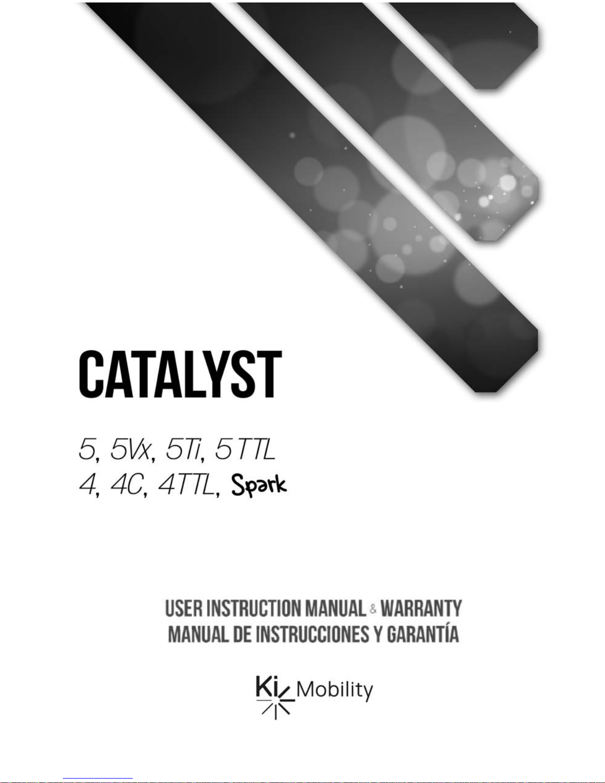
A. Your Catalyst / Spark & It’s Parts
1. Push Handle Backrest Tube
2. Pneumatic Tire
3. Aluminum Handrim
4. Spokes
5. Rear Wheel Hub
6. Quick-Release Axle
7. Aluminum Wheel Rim
8. Anti-Tipper
9. Axle Plate
10. Rear Frame Component
11. Cross Brace
12. Caster Fork
13. Caster Wheel
14. Caster Housing
15. Flip-Up Composite Footrest
16. Swing-Away Latch Release
17. Swing-Away Footrest / Footrest
18. Lifting Strap
19. Seat Sling
20. Swing-Away Padded Armrest
21. Backrest
1
21
2
20
19
18
17
16
15
14
13
11
12
3
4
10
9
8
7
6
5
Page 16

14
V. SET UP & USE OF YOUR WHEELCHAIR
B. Transit Use
It is always safest to transfer out of your wheelchair onto a seat in a motor vehicle with appropriate
seat and shoulder belts. Never use this wheelchair as a seat in a motor vehicle unless it has
been equipped with the Transit Option.
The Catalyst 5 Series and Spark Series wheelchair equipped with the Transit Option has been
tested to and passed the RESNA WC-4:2012, Section 19: Wheelchairs used as seats in motor
vehicles and ISO 7176-19:2008 Wheelchairs -- Part 19: Wheeled mobility devices for use as
seats in motor vehicles. RESNA and ISO standards are designed to test the structural integrity of
the wheelchair as a seat for use in a motor vehicle. These standards are also designed to create
compatibility with Wheelchair Tie-down and Occupant Restraint Systems (WTORS).
Not all configurations of the Catalyst 5 Series and Spark Series wheelchairs are compatible with
the Transit Option. Ki Mobility manages the configuration and does not offer the Catalyst 5 Series
and Spark Series wheelchair except in compatible configurations. If you make changes to your
Catalyst 5 Series and Spark Series wheelchair after your receive it, you should contact your
wheelchair provider or Ki Mobility to make sure it is appropriate to continue to use your wheelchair
as a seat in a motor vehicle.
If your Catalyst 5 Series wheelchair is equipped with the Heavy Duty Option and the Transit Option
you should not use it as a seat in a motor vehicle if you weigh more than 300 lbs.
If your Spark Series wheelchair is equipped with the Heavy Duty Option and the Transit Option you
should not use it as a seat in a motor vehicle if you weight more than 165 lbs.
Aftermarket seating may have replaced the original equipment seat and back support designed
and tested as part of the Transit Option. Your wheelchair provider should tell you if the seating they
provided is original equipment or replacement aftermarket seating. A complete system of
wheelchair frame, seating, Wheelchair Tie-down and Occupant Restraint Systems and a properly
equipped motor vehicle, that have all complied with the standards mentioned in this section,
should be in place before using a Catalyst 5 Series or Spark Series wheelchair equipped with the
Transit Option as a seat in a motor vehicle.
When using your wheelchair as a seat in a motor vehicle you should always observe the following
instructions:
• The rider must be in a forward-facing position.
• The rider and all items carried must not weigh more than 300 lbs for Catalyst 5 Series.
• The rider and all items carried must not weigh more than 165 lbs for Spark Series.
• Backpacks and pouches should be removed and secured separately in the motor vehicle.
In the event of an accident these items can become dangerous projectiles, which may
injure or kill you or other occupants of the motor vehicle.
• The rider must use a Wheelchair Tie-down and Occupant Restraint System that complies
with RESNA WC-4:2012, Section 18: Wheelchair tie-down and occupant restraint
systems for use in motor vehicles or ISO 10542-1:2012 Technical systems and aids for
disabled or handicapped persons -- Wheelchair tie-down and occupant-restraint
systems -- Part 1: Requirements and test methods for all systems.
Page 17
15
V. SET UP & USE OF YOUR WHEELCHAIR
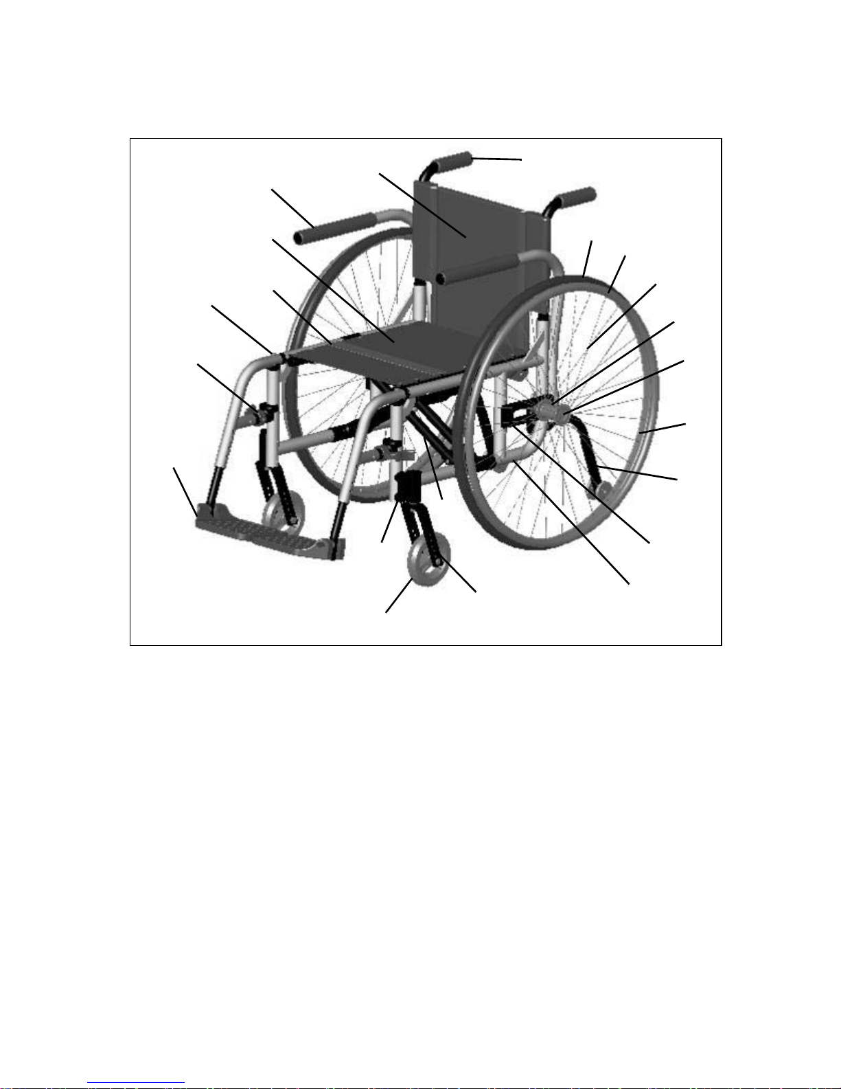
B. Transit Use
• Attach wheelchair tie-downs to the four
securement points (two front, two rear) on the
Catalyst or Spark wheelchair with the Transit
Option (Fig. 1) in accordance with the
wheelchair tie-down manufacturer’s
instructions and RESNA WC-4:2012, Section
18 or ISO 10542-1:2012 - Part 1.
• Attach occupant restraints in accordance with
the occupant restraint manufacturer’s
instructions and RESNA WC-4:2012, Section
18 or ISO 10542-1:2012, Part 1.
• Use of lap belts, chest straps, shoulder
harnesses, any other positioning strap system or positioning accessory should not be
used, or relied on as an occupant restraint, unless it is marked as such by the
manufacturer in accordance with RESNA WC-4:2012, Section 18 or ISO 10542-1:2012,
Part 1.
• Use of headrests, lateral supports or other positioning accessories should not be used, or
relied on as an occupant restraint, unless it is marked as such by the manufacturer in
accordance with RESNA WC-4:2012, Section 18 or ISO 10542-1:2012, Part 1 or RESNA
WC-4:2012, Section 20: Wheelchair seating systems for use in motor vehicles or ISO
16840-4:2009 Wheelchair seating -- Part 4: Seating systems for use in motor vehicles.
• After being fitted and adjusted, the top of the original equipment back upholstery should be
within 4 inches of the top of your shoulder.
• Any aftermarket seating should be tested to comply with RESNA WC-4:2012, Section 20
or ISO 16840-4:2009 - Part 4.
• Attach the seating to the wheelchair frame in accordance with the seating manufacturer’s
instructions and RESNA WC-4:2012, Section 20 or ISO 16840-4:2009 - Part 4.
• Use of lap belts, chest straps, shoulder harnesses, any other positioning strap system or
positioning accessory should not be used, or relied on as an occupant restraint, unless it is
marked as such by the seating manufacturer in accordance with RESNA WC-4:2012,
Section 20 or ISO 16840-4:2009 - Part 4.
• Use of headrests, lateral supports or other positioning accessories should not be used, or
relied on as an occupant restraint, unless it is marked as such by the seating manufacturer
in accordance with RESNA WC-4:2012, Section 20 or ISO 16840-4:2009 - Part 4.
• Aftermarket accessories such as trays, oxygen tank holders, oxygen tanks, IV poles, back
packs, pouches and other items not manufactured by Ki Mobility should be removed and
secured separately in the motor vehicle. In the event of an accident, these items can
become dangerous projectiles which may injure or kill you or other occupants of the motor
vehicle.
• If the wheelchair has been involved in an accident, you should not continue to use it, as it
may have suffered fatigue that may not be visible.
Fig. 1
Page 18

16
V. SET UP & USE OF YOUR WHEELCHAIR
B. Transit Use
DANGER: Failure to comply with transit use instructions, on pages 14 and 15, could result in
severe injury or death!
• When using this wheelchair as a seat in a motor vehicle you must remove the oxygen tank and
properly secure it separately.
DANGER: Failure to remove the oxygen tank and secure it properly in a motor vehicle can result
in it becoming a dangerous projectile in the event of an accident. This can cause severe injury or
death.
NOTE: To obtain copies of RESNA or ISO standards please contact the standards organizations
below:
RESNA
1700 North Moore St., Suite 1540
Arlington, VA 22209
Phone: 703-524-6686
Fax: 703-524-6630
Email: technicalstandards@resna.org
ANSI/RESNA Standards:
RESNA WC-4:2012, Section 18:
Wheelchair tie-down and occupant restraint systems for use in motor vehicles.
RESNA WC-4:2012, Section 19:
Wheelchairs used as seats in motor vehicles.
RESNA WC-4:2012, Section 20:
Wheelchair seating systems for use in motor vehicles.
International Organization for Standardization (ISO)
ISO Central Secretariat
1, ch. de la Voie-Creuse
CP 56
CH-1211 Geneva 20 Switzerland
Phone: +41 22 749 01 11
Fax: +41 22 733 34 30
Email: central@iso.org
ISO Standards:
ISO 10542-1:2012 Technical systems and aids for disabled or handicapped person --
Wheelchair tie-down and occupant-restraint systems -- Part 1:
Requirements and test methods for all systems.
ISO 16840-4:2009 Wheelchair seating -- Part 4:
Seating systems for use in motor vehicles.
ISO 7176-19:2008 Wheelchairs -- Part 19:
Wheeled mobility devices for use as seats in motor vehicles.
Page 19
17
V. SET UP & USE OF YOUR WHEELCHAIR
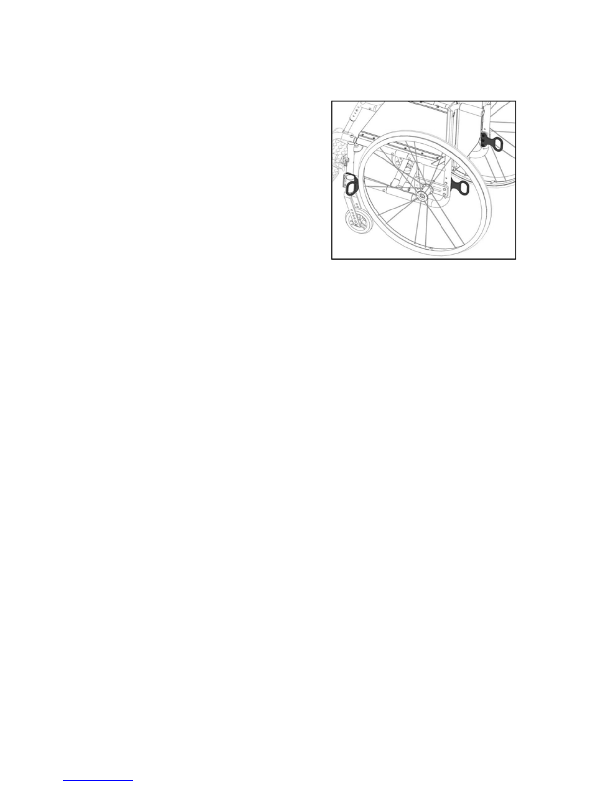
C. Height-Adjustable T-Arms
1. Installation
a. Slide the outer armpost into the receiver mounted to the wheelchair frame.
b. The armrest will automatically lock into place. Check to make sure the locking lever is as
shown (Fig. 2:B).
2. Height Adjustment
a. Rotate release lever (Fig. 2:A).
b. Slide armrest pad up or down to desired height.
c. Return lever to locked position against arm post.
d. Push arm pad until upper arm post locks firmly into place. Check to make sure the locking
lever is shown (Fig. 2:A).
3. Removing Armrest
a. Squeeze release lever (Fig. 2:B) and remove the armrest.
4. Replacing Armrest
a. Slide armrest back into receiver.
b. The armrest should lock back into place.
DANGER: Failure to comply with the instructions above may result in the armrest accidentally
disconnecting from the wheelchair and result in a fall or loss of control and may cause serious
injury or death.
DANGER: Never attempt to lift the chair by the armrests; they may break or disconnect resulting
in a fall or loss of control and may cause serious injury or death.
Fig. 2
A
B
Page 20
18
V. SET UP & USE OF YOUR WHEELCHAIR
D. Swing-Away Armrests
1. Installation (Fig. 3)
a. Slide armrest into the tube of the receiver that is mounted on
rear side of frame.
2. Swinging Away
a. Lift armrest slightly so it is free of the receiver bolt. Rotate away
from the chair.
3. Removing Armrest
a. Lift armrest straight out of receiver.
DANGER: These arms offer only a lock against rotation and are designed to bear a downward
force only. They will remove completely if pulled up on and cannot be used to lift or otherwise
handle the chair. Failure to comply with the instructions above may result in the armrest
accidentally disconnecting from the wheelchair and result in a fall or loss of control and may cause
serious injury or death.
Fig. 3
Page 21
19
V. SET UP & USE OF YOUR WHEELCHAIR
E. Angle Adjustable Locking Flip Up Extendable Armrest
Adjustments
1. Set the angle of the armrest based on your preferences. There are five holes that can be used
to set the angle (Fig. 4:A). Tighten the bolt once angle is set.
2. Set the length of the armrest based on your preferences. To adjust the length, remove the
bolts and spacer (Fig. 4:B) on the tube and the screw (Fig. 4:C) closest to the back of the
chair. Slide the armrest to desired length available by the predrilled holes and reinstall the
screw and bolts.
3. Set the height of the armrest on the chair based on your preferences. There are four holes on
the armrest that allow for two different height settings for each set of holes on the back tube.
Use the holes that provide the correct height setting for the user. The two bolts (Fig. 4:D) pass
through the spacer (Fig. 4:E), sleeves (Fig. 4:F), back posts and into the armrest.
Use
1. Press the release lever (Fig. 4:G) up to release the armrest and swing it upwards.To return the
armrest to the operating position, push the armrest down until the lever clicks and locks.
DANGER: Always make sure the arms are locked in place before using them for repositioning
yourself, failure to do so may result in a fall or loss of control and may cause serious injury or
death.
DANGER: Never attempt to lift the chair by the armrests; they may break or disconnect resulting
in a fall or loss of control and may cause serious injury or death.
Fig. 4
A
F
E
D
C
B
G
Page 22
20
V. SET UP & USE OF YOUR WHEELCHAIR
F. Flip Back Height Adjustable T-Arm
Use
1. To flip back the armrest, pull the release lever (Fig. 5:A) up and lift the armrest assembly up
and back.
2. To return the armrest down, lower the armrest assembly until the release lever locks back into
place.
To Increase/Decrease the Front End Length of Armrest
1. Pull the height adjustment lever (Fig. 6:A) and remove the
upper T-Arm assembly (Fig. 6:B).
2. Rotate the upper T-Arm assembly and reinstall into the
armrest.
3. Close the height adjustment lever (Fig. 6:A) to secure.
NOTE: The armrest pad is not centered on the tube,
widthwise or lengthwise. This offers two different length
options - longer or shorter on the front end of the chair.
This also offers two options with the armrest pad. When
the long end of the armrest is on the front end of chair, the
amrest pad hangs more to the outside of the chair. The
armrest pad hangs more to the inside of the chair when the
short end of pad is on the front end of chair. The armrests
can also be switched to the opposite sides to allow more
options regarding the amount of front end pad length and
side pad length.
To Increase/Decrease the Height of the Armrest
1. Pull the height adjustment lever (Fig. 7:A) and slide the
upper T-Arm assembly to desired height.
NOTE: Each hole on the upper T-Arm assembly bar
represents a height setting that can be used in ½”
increments.
2. Close the height adjustment lever (Fig. 7:A) to secure.
Loosen or tighten this
screw to decrease or
increase tension when
flipping armrest
assembly.
Fig. 5
A
Fig. 6
A
B
A
Fig. 7
Page 23
21
V. SET UP & USE OF YOUR WHEELCHAIR
G. Flip-Back / Flip-Back Height Adjustable Armrests
1. Move for transfer
Press and hold lever underneath front transfer bar
(Fig. 8:A) while simultaneously lifting up. Armrest
will pivot up and slightly behind the back posts.
2. Height adjustment
a. Rotate release lever (Fig. 8:B).
b. Slide armrest pad up or down to desired
height.
c. Return lever to locked position against arm
post.
d. Push arm pad until upper arm locks firmly into place. The armrest should lock back into
place.
DANGER: Always make sure the arms are locked in place before using them for repositioning
yourself. Failure to do so may result in a fall or loss of control and may cause serious injury or
death.
DANGER: Never attempt to lift the chair by the armrests; they may break or disconnect resulting
in a fall or loss of control and may cause serious injury or death.
H. Armrest Warnings
• All Ki Mobility armrests are designed to detach from the chair and will not bear even the
weight of this chair.
• NEVER lift this chair by its armrests. The armrests will release and the user may fall.
• Lift this chair only by non-detachable parts of the main frame.
WARNING: Failure to heed these instructions may result in a fall, tip-over or loss of control
causing severe injury to the user or others.
Fig. 8
A
B
Page 24

22
V. SET UP & USE OF YOUR WHEELCHAIR
I. Hangers
1. Installation
a. Place swing-away pivot saddle into the receiver on front frame tube with the footrest facing
either inward or outward from the frame (Fig. 9).
b. Rotate the footrest so that it aligns with the frame until it locks into place in the latch block
(Fig. 10).
2. Swinging the footrest away
a. Push release latch toward the frame.
b. Rotate footrest outward or inward as desired.
3. Removal
a. To remove the footrest, push release latch toward the frame.
b. Lift the footrest straight upward to remove. You may also swing the footrest inward or out-
ward before lifting it off.
WARNING: Always make sure the hangers are locked in place before using them or riding the
wheelchair. Failure to do so may result in a fall or loss of control and may cause serious injury or
death.
DANGER: Never attempt to lift the chair by the hangers; they may break or disconnect resulting
in a fall or loss of control and may cause serious injury or death.
Fig. 9
Fig. 10
Page 25
23
V. SET UP & USE OF YOUR WHEELCHAIR
J. Swing Away Hangers with 4-Way Latch
1. Installation
a. Place swing away pivot saddle into the receiver on front
frame tube (Fig. 11:A).
b. Rotate the footrest so that it aligns with the frame and locks
into place in the latch block (Fig. 11:B).
2. Swinging the Footrest Away
a. Push or pull on release latch.
b. Rotate footrest outward or inward as desired.
3. Removal
a. To remove footrest, push or pull release latch.
b. Lift the footrest straight upward to remove. You may also
swing the footrest inward or outward before lifting it off.
4. Rotating (Fig. 12)
The 4-way latch has eight possible configurations, four with the
curve of the lever facing outward and four with the curve of the lever
facing inward. See Fig. 13 for possible configurations.
a. To rotate the 4-way latch, remove the screw using a 3mm Allen wrench while the hanger is
still on the chair (spring must be engaged to remove and reinsert screw and keeping the
hanger on the chair keeps the spring engaged). Ensure nut does not fall out.
b. Rotate the 4-way latch to desired orienta-
tion and reinsert screw with 3mm Allen
wrench. Ensure that nut stays in position
while tightening the screw. Do not overtighten screw or mechanism will bind.
NOTE: To reverse the 4-way latch, the same
screw is removed, but the hanger has to be
removed from the latch block. Once removed,
slide the latch off, flip over and reinstall. Ensure spring is engaged, by pushing and holding the
latch button in, and nut stays in position while reinstalling the screw.
NOTE: In-line position is not achievable with the Pro ELR Footrest option.
Fig. 11
A
B
Screw
Nut
Fig. 12
Eight Possible Configurations
Lever Facing
Outward
Lever Facing
Inward
Standard Position
Fig. 13
Page 26
24
V. SET UP & USE OF YOUR WHEELCHAIR
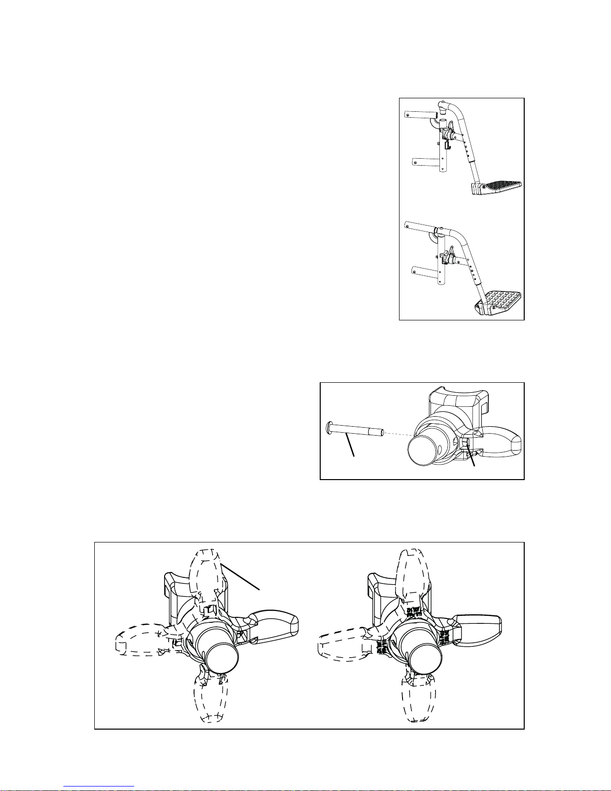
K. Extension Tubes
1. Adjustment
a. Remove mounting fasteners from each side of the hanger tube.
b. Slide footrest extension tube to the desired height.
c. Line up holes and reassemble fasteners in desired hole through hanger and extension tube.
d. Follow same procedure on opposite side (Fig. 14 & 15).
At the lowest point, footrests should be at least 2½ inches off the ground. If set too low, they may
"catch" on obstacles you would expect to find in normal use. This may cause the chair to stop
suddenly and tip forward (Fig. 16).
To Avoid a Trip or Fall When You Transfer:
a. Make sure your feet do not get caught in the space between the footrests.
b. Avoid putting weight on footrests as the chair may tip forward.
Fig. 15
Fig. 14
Fig. 16
2.5"
Page 27
25
V. SET UP & USE OF YOUR WHEELCHAIR
L. Elevating Leg Rest
1. Installation
a. Place swing-away pivot saddle into the receiver on front frame tube with the footrest facing
either inward or outward from the frame. Similar to swing-away footrest pictured in Fig. 9
and Figure 10 on page 22.
b. Rotate the footrest so it aligns with the frame until it locks into place in the latch block.
2. Removal
a. To remove footrest, push release latch toward the frame.
b. Rotate footrest outward and lift.
3. Extension Tube Adjustment
a. Remove mounting bolt that is threaded into the leg rest tube in the center of the pad bracket
(Fig. 17:C). In some circumstances this bolt may be inserted in the tube below the pivot
bracket.
b. Slide footrest extension tube to the desired height.
c. Line up holes and replace the bolt through leg rest tube and extension tube.
d. Follow same procedure on opposite side.
4. Angle Adjustment
a. To raise, lift up on the rear of the extension tube (Fig.
17:A). The rod will slide through the ratchet in this direction. Stop at desired position.
b. To lower, firmly hold the leg from behind the extension
tube (Fig. 17:A). Pull forward on the lever (Fig. 17:B)
and while holding the lever, lift the leg rest. Releasing
the lever will cause the leg rest to lock into position.
To Avoid a Trip or Fall When You Transfer:
a. Make sure your feet do not get caught in the space
between the footrests.
b. Avoid putting weight on the footrests as the chair may tip forward.
WARNING: At the lowest point, footrests should be AT LEAST 2 ½ INCHES off the ground. If set
too low, they may "catch" on obstacles you would expect to find in normal use. This may cause
the chair to stop suddenly and tip forward and could result in a fall or loss of control and may
cause serious injury or death.
DANGER: Never attempt to lift the chair by the hangers; they may break or disconnect resulting
in a fall or loss of control and may cause serious injury or death.
Fig. 17
B
C
A
Page 28
26
V. SET UP & USE OF YOUR WHEELCHAIR
M. Pro Elevating Leg Rest
Installation
NOTE: The Pro ELR is mounted onto the chair the same way as a swing away hanger.
1. Place swing away pivot saddle into the receiver on front frame tube with the leg rest facing
either inward or outward from the frame.
2. Rotate the leg rest so that it aligns with the frame and locks into place in the latch block.
Adjusting Height of Calf Pad
1. Loosen nut (Fig. 18:A) using a 10mm wrench.
2. Slide calf pad arm up or down to desired location.
Retighten nut.
Adjusting Depth of Calf Pad
1. Remove screw (Fig. 18:B) and nut (Fig. 18:C) on calf
pad arm using a 5mm Allen wrench and a 13mm
wrench.
2. Pick the desired location based on the four predrilled
holes and reinstall screw and nut.
Adjusting Length of Footrest
1. Loosen set screw (Fig. 19:A) with a 4mm Allen
wrench.
2. Slide extension tube in or out to get to desired
length and secure by tightening set screw.
Adjusting Knee Height
1. Using two 10mm socket wrenches, loosen the two
nuts (Fig. 20:A) on the cover.
2. Adjust knee height to desired setting.
3. Retighten the two nuts (Fig. 20:A) after desired
height is attained.
Use
1. To raise the Pro ELR, lift the leg rest tube (Fig. 21:A)
to desired angle of elevation.
2. To lower the Pro ELR, press and hold the lever lock
(Fig. 21:B) while pushing the leg rest tube (Fig. 21:A) down.
NOTE: Remove the Pro ELR from the chair or remove
weight from the Pro ELR while lowering to avoid a
sudden drop when the lever lock is pushed.
NOTE: The calf pad can swing outward to clear the
front of the chair for transfers.
Removal
1. To remove leg rest, push or pull release latch.
2. Lift the leg rest straight upward to remove. You may
also swing the leg rest inward or outward before
lifting it off.
Fig. 18
A
B
C
Fig. 19
A
1 ½”
range of
motion
Fig. 20
A
Fig. 21
A
B
Page 29
27
V. SET UP & USE OF YOUR WHEELCHAIR
N. Adjustable Height Backrest
1. Height Adjustment (Fig. 22)
a. On the rear side frames there are holes that are one inch apart
that affix the back canes.
b. Remove the two bolts from each rear side frame.
c. After selecting the desired height, replace bolt through frame
and backrest tube.
d. On the bottom of the upholstery is a tab and zip tie. Either run
the frame bolt through the zip tie or if there is not enough room
use the extra bolt that was sent with the back upholstery.
e. Tighten and remove any excess zip tie.
O. Depth Adjustable Backrest
1. Angle Adjustment
a. To adjust the angle of the backrest, remove the M6 bolt and nut
(Fig. 23:A) on both sides going through back plate and back
tube.
b. Rotate the push handle (Fig. 23:B) forward or rearward until you
have reached the desired angle.
c. Reinsert the two M6 bolts through the back plate into the
threaded barrels.
d. Repeat on the other backrest.
2. Folding
a. To fold the backrest, push the lever (Fig. 23:C) toward the front of
the chair. The backrest will pivot and fold forward. Repeat on the other side.
3. Depth Adjustment
a. To change the depth of your Catalyst 5, remove the bolt and
nut on each side of the back plate at location (Fig. 24:E).
b. Remove the bolt and nut from each side of the Strike (Fig.
24:F). The backrest assembly (Fig. 24:D) can then be repositioned into an available hole on the side frame.
c. After repositioning, replace the bolts and nuts into the side
plate through location (Fig. 24:E) and the strike plate (Fig.
24:F).
Fig. 22
Fig. 23
B
C
A
Fig. 24
D
E
F
Page 30

28
V. SET UP & USE OF YOUR WHEELCHAIR
P. Catalyst Half-Folding Backrest
WARNING: Always have a qualified technician set up your wheelchair with the accessories you
plan to use daily. Changes to how you sit or changes in your weight require your chair to be
readjusted by a qualified technician. Always use anti-tips while you acclimate to any changes in
your chair set up. Failure to comply with the instruction above could result in serious injury or
death.
Use (Fig. 25)
1. Press the release lever in towards the back cane while folding the back cane down.
2. Lift the back cane until it "clicks", or locks, to return it to operating position.
DANGER: Do not place or hang objects from the backrest canes. Doing so could result in an
accidental release of the fold down lever on the half-folding backrest which could result in a fall or
loss of control and may cause serious injury or death.
DANGER: Do not use chair if back cane is not in operating position. Doing so could result in a
fall and may cause serious injury or death.
Height Adjustment
Refer to the Adjustable Height Backrest section in this owner’s manual.
Fig. 25
Folding Down
Folding Up
Page 31

29
V. SET UP & USE OF YOUR WHEELCHAIR
Q. Catalyst Recline Back
WARNING: Back height, back angle, seat depth, recline angle, seat height, size/position of rear
wheels, size/position of front casters and any added weight to the back of the chair such as
accessories, backpacks and oxygen tanks all relate to and affect the stability of the wheelchair.
Any adjustments or change to one or more of the items listed above can decrease the stability of
the wheelchair. Take caution when making changes to the above items. Consult a qualified
technician when adjusting back height, back angle, seat depth, seat height, size / position of rear
wheels and size/position of front casters. Inappropriate adjustments can result in serious injury.
Reclining Back Notes for Operation
1. After making any adjustments to the system, make sure all attaching hardware is securely
tightened.
2. Always make sure the wheelchair is stable in the fully reclined position. Depending on the
angle of the backrest, the full recline position will be 65° and is relative to the full upright
position. Full upright position is measured as 0°.
3. Always engage the wheel locks while reclining or inclining to ensure maximum safety of the
patient.
4. Before using the reclining backrest, make sure the anti-tippers are adjusted properly to ensure
the wheelchair will not become unstable when in use. See Anti-Tip Instructions on page 40.
DANGER: Tilting or reclining the chair beyond level greatly increases the risk of falling out of the
chair, which can result in serious injury or death.
Recline / Incline
1. Unlock the system prior to recline or incline
adjustment by removing the locking pin (Fig.
26:A) from locking hole (Fig. 26:B) on each
recline trigger.
2. Make sure wheel locks are engaged and
wheelchair is on a level surface.
3. Grip the handles securely and slowly depress
both reclining triggers (Fig. 26:C) at the same
time to release the gas cylinders. This will allow
you to adjust the backrest position as follows:
a. Reclining - to open the angle of the backrest
relative to the seat frame, or recline, by
applying downward force on gas springs.
b. Inclining - return to upright position by
applying force upward and pushing the
backrest towards the front of the wheelchair.
4. Once desired backrest recline angle has been
achieved, slowly release both reclining triggers.
5. To lock the system, insert the locking pin (Fig. 26:A) into the locking pin hole (Fig. 26:B). It is
recommended that you always lock both reclining backrest triggers when you are done
positioning the patient.
A
A
B
C
C
B
Fig. 26
Page 32

30
V. SET UP & USE OF YOUR WHEELCHAIR
Q. Catalyst Recline Back
Moving Recline System Along Rear Frame
WARNING: Remove patient from wheelchair prior to making this adjustment. Failure to do so
could result in death or serious injury.
1. Depending on where the mounting plates are installed on the frame, you can adjust the
reclining backrest as follows along the rear frame: 1" shorter, 2" shorter or 2" deeper.
2. Using a 4mm Allen wrench and a 10mm wrench, remove flat head cap screws (Fig. 27:A), half
saddles (Fig. 27:B) and M6 nylock hex nuts (Fig. 27:C).
3. Move assembly to desired location along rear frame.
4. Replace the saddles in between plate and rear side frame (Fig. 27:B), reinsert the flat head cap
screws (Fig. 27:A) and replace and tighten M6 nylock hex nuts (Fig. 27:C) until securely
fastened.
5. Repeat on opposite side.
C
B
B
A
Fig. 27
Page 33

31
V. SET UP & USE OF YOUR WHEELCHAIR
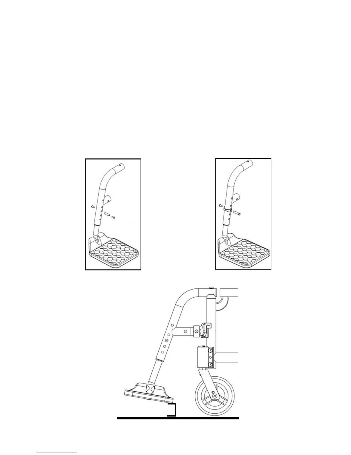
R. Wheel Installation & Removal (Optional on some models)
1. Installing Wheels:
a. Push in the axle release button on the axle to allow the
locking balls to retract. Make note of the difference
between the extended and depressed position of the
axle release button and its effect on the locking balls on
the other end of the axle (Fig. 28).
b. Insert the axle into the bearing housing on the wheel if it’s
separate.
c. Push on quick release button again and slide axle into
axle sleeve (Fig. 28).
d. Release the button to lock axle in sleeve. If release but-
ton does not fully extend and the locking balls do not move into the locked position after
releasing the button, the axle length needs to be adjusted (Fig. 29).
2. Adjusting Axles
a. To adjust the axle you will need a 19mm wrench to turn
the outside axle nuts.
b. You will also need an 11mm wrench to hold the ball
bearings on the opposite end of the axle and prevent
the axle from turning.
c. When the wheel is installed, if the axle does not lock,
loosen the axle nut until it locks and axle can move in
and out slightly when locked. If the axle locks, but
moves in and out slightly, proceed to step d.
d. Turn the axle nut counterclockwise until it is tight then
turn the axle nut clockwise 1/3 turn at a time. Check to
see if it is properly adjusted after each 1/3 turn. When properly adjusted there should be no
perceptible movement of the axle in and out in the sleeve, but the axle release button
should be easy to push in.
Review and understand Section R. Wheel Installation & Removal before attempting an axle
adjustment!
3. Removing Wheels
a. Hold the wheel close to the hub and push in the button on the outside end of the axle.
b. While still holding the button, pull the wheel and axle out of the axle sleeve.
DANGER: Make sure the push button is completely extended and the locking balls on the inside
of the chair are fully engaged before operating the wheelchair. Failure to do so may result in the
wheel falling off and may cause serious injury or death.
Fig. 28
Fig. 29
Page 34
32
V. SET UP & USE OF YOUR WHEELCHAIR
S. Catalyst 5, 5Ti & Spark
1. Center of Gravity (Fig. 30)
Moving the axle sleeve within the axle plate changes the weight
distribution between the casters and the rear wheels. As it is moved
forward, more of the weight is on the rear wheel. This takes weight off
the front casters and can make it easier to maneuver the wheelchair. It
also causes the wheelchair to be less staple and makes tipping
backward easier. The further back the axle, the more stable the chair
becomes. Ki Mobility recommends you work with your authorized Ki
Mobility supplier when considering making this adjustment.
WARNING: You should always use anti-tips when trying your chair after making adjustments to
the axle placement. Failure to do so could cause you to tip over or lose control and cause serious
injury or death.
DANGER: Adjusting the axle plate too far forward can result in a chair that may tip over
backward resulting in a fall or loss of control and cause severe injury or death.
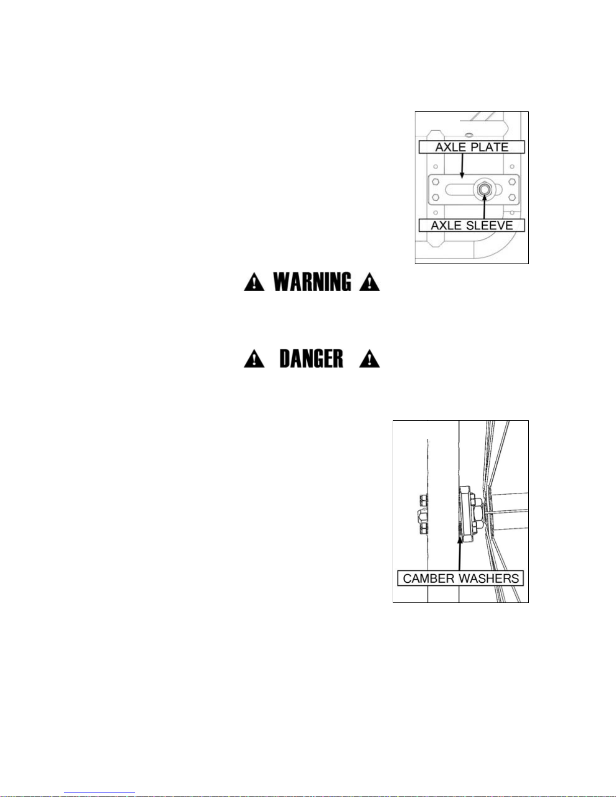
2. Wheel Camber (Fig. 31)
Adding camber to an axle plate provides more lateral stability to the
wheelchair due to the increased width of the wheel base. Additional
camber can also make turning easier and can improve access to
the handrims. Wheel camber is chosen during the ordering
process. No matter what camber was originally set up for the
wheelchair it can be changed. To adjust the camber, remove the
bolts in the axle plate. If more camber is desired, add one washer
for every one degree. Do not add more than six washers to a bolt! If
less camber is desired, remove one washer for every degree you
want to remove. After placing the desired number of washers,
reinstall the axle plate and the bolts. Do the same for the axle plate
on the opposite side of the wheelchair.
Fig. 30
Fig. 31
Page 35

33
V. SET UP & USE OF YOUR WHEELCHAIR
S. Catalyst 5, 5Ti & Spark
3. Adjusting the Wheel Base Width (Fig. 32)
The sleeve that holds the axle is adjustable in and out. Adjusting
this sleeve allows the user to move the wheels closer or further
away from the axle plate which increases or decreases the overall
width. Increasing the overall width will improve side to side
stability, but may make it harder to fit through doors. Decreasing
the overall width may improve accessibility. When decreasing the
overall width, make sure you do not create a condition where the
wheels rub on armrests or other parts of the chair.
a. Loosen the nuts and turn the axle sleeve in or out as
desired (Fig. 32:A). Count the number of threads showing
and repeat on the opposite side.
b. Retighten nuts.
4. Rear Seat Height Adjustment
The rear seat height can be adjusted by moving the axle plate
vertically in the predrilled frame holes. This adjustment allows a 4" vertical seat height adjustment.
NOTE: A front caster adjustment should be made to correspond with any change in seat
height. See Section Z. Caster Forks.
Fig. 32
Page 36

34
V. SET UP & USE OF YOUR WHEELCHAIR
T. Catalyst 5Vx
1. Center of Gravity (Fig. 33):
Moving the axle plate on the frame shifts the center of gravity changing the weight
distribution between the casters and the rear wheels. As it is moved forward, more
of the weight is on the rear wheel. This takes weight off of the front casters and can
make it easier to maneuver the wheelchair. It also causes the wheelchair to be less
stable and makes tipping over backward easier. The further back the axle, the more
stable the chair becomes. Ki Mobility recommends you work with your authorized
Ki Mobility supplier when considering making this adjustment.
WARNING: You should always use anti-tips when trying your chair after making adjustments to
the axle placement. Failure to do so could cause you to tip over or lose control and cause serious
injury or death.
DANGER: Adjusting the axle plate too far forward can result in a chair that may tip over
backward resulting in a fall or loss of control and cause severe injury or death.
2. Rear Seat Height Adjustment (Figure 34):
The seat height can be adjusted by moving the axle sleeve vertically in
the predrilled holes in the axle plate. This adjustment allows a 5"
vertical seat height adjustment.
NOTE: A front caster adjustment should be made to correspond
with any change in seat height. See Section Z. Caster Forks.
3. Adjusting the Wheel Base Width (Fig. 34)
The sleeve that holds the axle is adjustable in and out. Adjusting this
sleeve allows the user to move the wheels closer or further away from
the axle plate which increases or decreases the overall width.
Increasing the overall width will improve side to side stability, but may
make it harder to fit through doors. Decreasing the overall width may
improve accessibility. When decreasing the overall width, make sure
you do not create a condition where the wheels rub on armrests or
other parts of the chair.
a. Loosen the nuts and turn the axle sleeve in or out as desired (Fig. 34). Count the number of
threads showing and repeat on the opposite side.
b. Retighten nuts.
Fig. 33
Fig. 34
Page 37

35
V. SET UP & USE OF YOUR WHEELCHAIR
U. Catalyst 4 & 4C
1. Rear Seat Height Adjustment (Fig. 35)
Rear seat height can be adjusted by moving the axle plate vertically in the predrilled holes in the
frame.
a. Remove the two hex headed bolts using a 10mm wrench.
b. Reposition the axle plate up or down in 1" increments depending on the change you wish to
make. This adjustment allows for a total vertical seat height adjustment range of 5".
NOTE: A front caster adjustment should be made to correspond with any change in seat height.
See Section Z. Caster Forks.
Fig. 35
Page 38
36
V. SET UP & USE OF YOUR WHEELCHAIR
V. Spark - Folding Frame
1. Folding Frame
Before attempting to fold the frame, remove any seating system that is attached. Also, flip up or
remove any footplates.
a. Lift upwards on the strap (Fig. 36:A). This will disengage cross brace supports (Fig. 37:C)
from the seat hooks.
b. To reopen the frame, push down on one of the cross braces (Fig. 36:B) until the cross brace
supports (Fig. 37:C) have completely engaged with the seat hooks.
Fig. 37
C
Fig. 36
A
B
Page 39

37
V. SET UP & USE OF YOUR WHEELCHAIR
W. Spark - Adjusting Frame Width
1. Adjusting Frame Width
To change the width of the frame:
a. Remove the bolts that connect the cross braces and the cross brace extensions (Fig. 38:A)
on both sides of the frame.
NOTE: Remember which hole the bolt (Fig. 39:B) is using in the upper pivot bracket (Fig. 39:C).
b. Remove bolt (Fig. 39:D) from center of cross braces.
c. Slide cross brace extensions in or out to reach the desired overall width. Each frame is avail-
able with three seat widths in 1" increments.
To measure the width, take a measure from the outside of the seat frame on one side and the
outside of the seat frame on the other side.
d. After you locate the desired width, slide the bolt (Fig. 39:B) back through the cross braces
and cross brace extensions on both sides. Then, locate the center hole that corresponds. If
the bolt is in the middle hole of the extension, locate the center hole in the middle.
X. Upholstery Fabric
1. You must immediately replace seat and back upholstery that has worn through and shows
signs of failing. If you fail to do so, the seat or back may fail.
2. The seat sling material will weaken over time. Look for fraying, thin spots, or stretching of
fabrics, especially at edges and seams. This should be done weekly.
3. The repeated action of transferring to your wheelchair will weaken sling material and result
in the need to inspect and replace the seat more often.
4. Be aware that laundering or excess moisture will reduce flame retardation of the fabric.
5. Contact your wheelchair provider if you have concerns about your seat or back, or feel it
needs to be replaced.
WARNING: Failure to comply with these instructions may result in damage to your wheelchair, a
fall or loss of control causing severe injury to the user or others.
Fig. 38
A
Fig. 39
D
C
B
Page 40

38
V. SET UP & USE OF YOUR WHEELCHAIR
Y. Wheel Locks
Catalyst wheelchairs are shipped with one of several different types of wheel locks preinstalled.
• Push to Lock
• Pull to Lock
• Push to Lock (Flush Mount)
• Short Thro Scissor
The clamp assembly works the same for all wheel locks.
a. Using a 5mm Allen wrench, turn one of the screws
in the clamp until loosened (less than one turn).
b. Repeat the same process with the second of the
two screws so the clamp can be adjusted on the
frame.
c. Adjust the clamp toward the rear wheel so, when
engaged, the wheel lock compresses the tire and
prevents any wheel movement (Fig. 40).
d. Make sure wheel lock arms embed in tires at least
1/8 inch when locked. If you fail to do so, the locks
may not work (Fig. 41).
e. Retighten the screws.
Wheel lock clamps require a torque setting of 100
in./lbs.
Rear wheel locks are NOT designed to slow or stop a
moving wheelchair. Use them only to keep the rear
wheels from rolling when your chair is at a complete
stop.
• NEVER use rear wheel locks to try to slow or stop
your chair when it is moving. Doing so may cause you to veer out of control.
• To keep the rear wheels from rolling, always set both rear wheel locks when you transfer to
or from your chair.
• Low pressure in a rear tire may cause the wheel lock on that side to slip and may allow the
wheel to turn when you do not expect it.
• Make sure lock arms embed in tires at least 1/8 inch when locked. If you fail to do so, the
locks may not work.
DANGER: Failure to read or comply with these instructions may result in a fall or loss of control
causing severe injury to the user or others.
Fig. 40
Fig. 41
Page 41

39
V. SET UP & USE OF YOUR WHEELCHAIR
Z. Caster Forks
The caster forks allow the interchanging of casters and the adjusting of the front seat height (Fig.
42).
To adjust:
a. Loose the axle nut and remove the axle.
b. You can reposition the axle and caster up or down in ½" increments
to change the front seat height.
c. Replace axle and tighten nut.
If a different caster is desired, determine the difference in height between
the new and old caster (to maintain the seat height: 1" taller caster size
adjusts up one hole position).
If you have changed your front seat height you should square the caster
housing (see below).
AA. Caster Angle Adjustment
Standard Caster Housing
The caster housing should always be at a 90° angle to the floor (perpendicular to the ground). This
is adjusted using a special fastener and an eccentric nut (Fig. 43).
a. To change the angle of the caster housing, it is best to place
the chair on a flat surface.
b. Remove the bolt from the inside of the frame.
c. Place a square against the table and the front of the caster
housing to realign the housing.
d. Push the bolts back through the frame.
e. Rotate the eccentric nuts independently until they fit both on
the bolt and within the slot of the caster housing.
f. Retighten the two bolts slowly ensuring the housing remains
square.
g. Repeat the process for the other caster.
Performance Caster Housing
The caster barrel should always be at a 90° angle to the floor
(perpendicular to the ground).
a. Pull tab on caster housing slightly outward and remove pro-
tective cover (Fig. 43:A) by lifting straight up.
b. Locate the two socket head screws (Fig. 43:D). Using a
5mm Allen key, loosen each screw two complete turns.
c. Locate the Adjustment Screw (Fig. 43:B). Using a 5mm Allen
key, turn clockwise to move caster fork forward or counterclockwise to move caster forks rearward in order to achieve
90° angle to the floor.
d. Using a square against the caster barrel (Fig. 43:C), check to
make sure casters are positioned perpendicular to the
ground. Once achieved, retighten socket head bolts (Fig.
43:D) until secure.
e. Replace protective cover (Fig. 43:A). Repeat steps on opposite side.
Fig. 42
Fig. 43
Standard
Performance
A
B
C
D
Page 42

40
V. SET UP & USE OF YOUR WHEELCHAIR
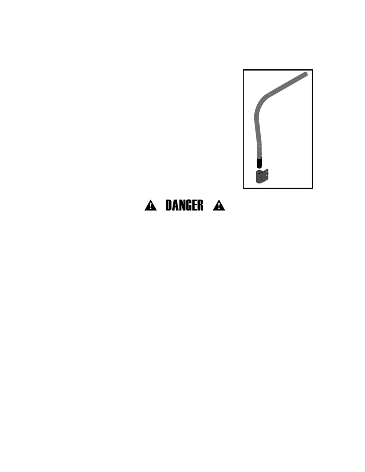
BB. Anti-Tips (Optional)
Anti-tip tubes help prevent your wheelchair from tipping over backwards. When adjusted properly
they provide a significant increase in rearward stability. Your stability can be affected by traversing
uneven ground, a ramp, slope or other surface that changes your relationship to gravity. Your
stability can also be affected by other forces acting on you and your wheelchair, such as someone
pushing down or leaning on your push handles or other parts of your chair. This can happen to
even the most experienced wheelchair user. People in your environment do not necessarily
understand they are impacting your stability.
WARNING: Ki Mobility strongly recommends the use of Anti-Tip tubes! Anti-tips must be
used at all times. Whether traversing uneven ground or sitting in a crowded room, the
unexpected may occur and your weight can dramatically shift causing a fall which could cause
serious injury or death.
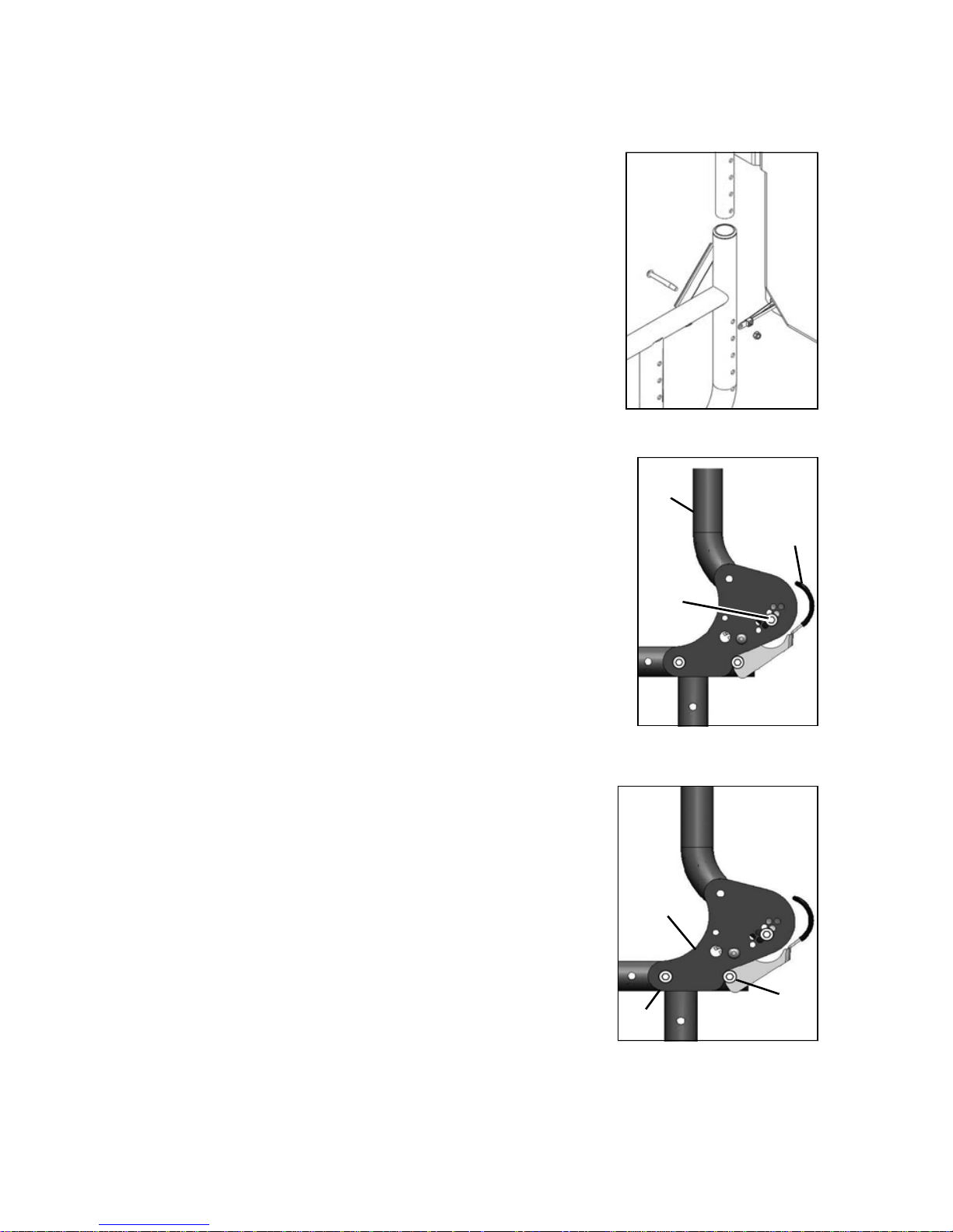
1. Installing Anti-Tips (Fig. 44)
• Compress the 2nd detent button on the anti-tip tube so the
front detent button is drawn inside.
• Insert the anti-tip tube into receiver mounted on the side
frame.
• Rotate the anti-tip tube downward until the small wheels are
adjacent to the floor. The detent button should now be
aligned with a hole on the receiver. Release the detent
button and it will engage with the receiver.
• Insert second anti-tip tube the same way.
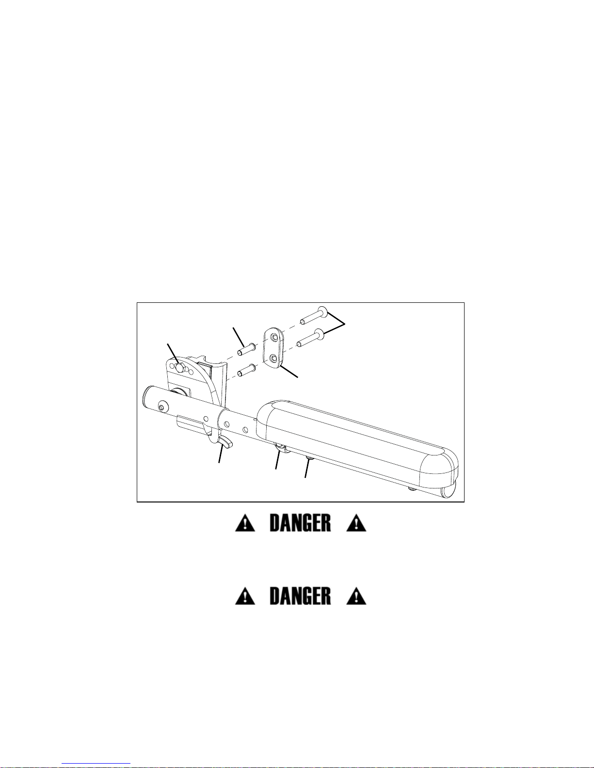
2. Adjusting Position of Anti-Tip Receiver (Fig. 45)
You should only need to adjust your Anti-Tip Receiver if you change your chair. If you make
changes that require you to adjust the position of your receiver, follow these steps:
• Remove bolts that connect the anti-tip tube receiver to the
side frame of your chair.
• The holes are in 1" increments so you can move it farther up
on the frame or lower on the frame. Place the bracket at the
desired height.
• Reinsert bolts and tighten. (If the bolts also connected the
armrest and the axle plate you may need to contact your
supplier for additional hardware)
• Repeat with second anti-tip tube receiver. Both brackets
should be at exactly the same height.
• Replace anti-tip tubes as instructed above.
DANGER: Failure to read and heed these instructions may result in damage to your wheelchair,
a fall or loss of control causing severe injury to the user or others.
Fig. 44
Fig. 45
Page 43

41
V. SET UP & USE OF YOUR WHEELCHAIR
BB. Anti-Tips (Optional)
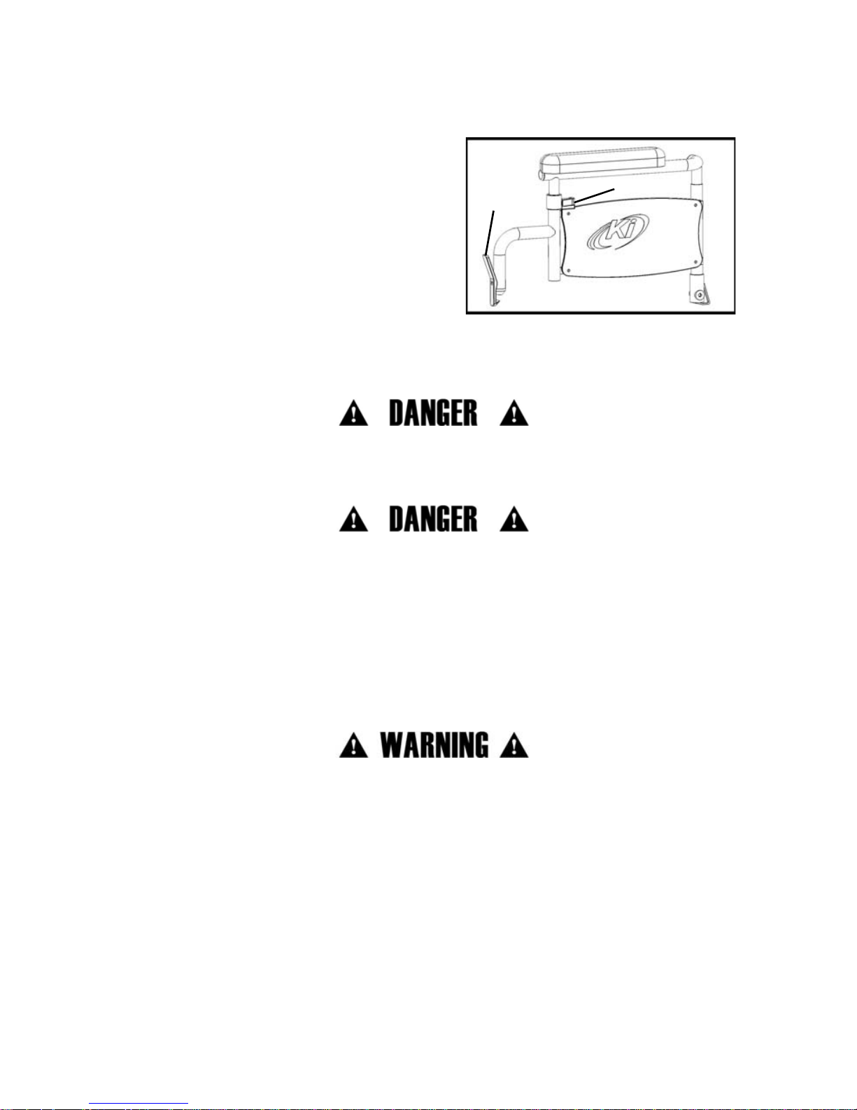
3. Adjusting Height of Wheel Extension (Fig. 46)
The anti-tip tube wheel extension may need to be raised or lowered
to achieve the proper clearnace of 1½" to 2" above the ground.
a. Compress the detent buttons until they are inside the tube
wall. This will allow the outer tube to slide up and down on
the inner tube.
b. Slide the extension tube up or down until you achieve the
desired height.
c. Release the buttons.
d. Adjust the second wheel extension the same way. Both
wheels should be at exactly the same height.
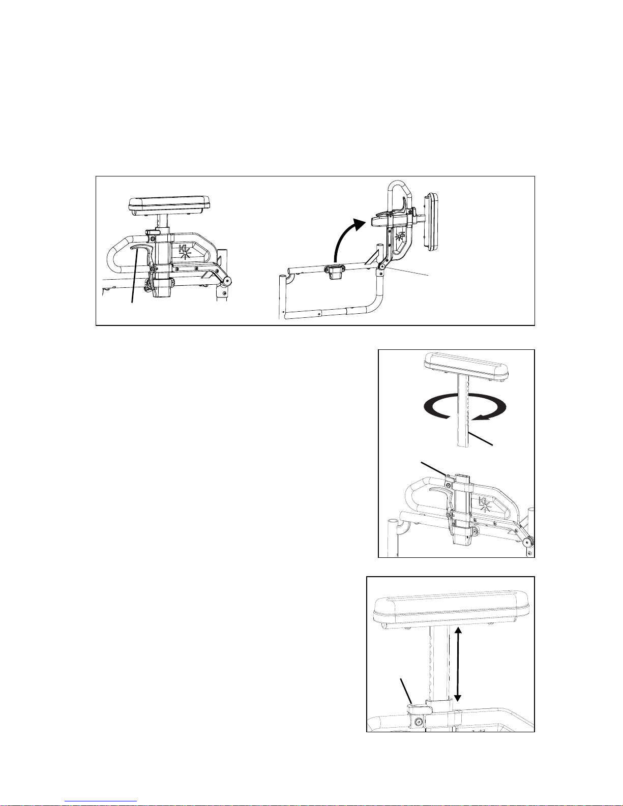
4. Turning Anti-Tip Tubes Up (Fig. 47)
You may find it necessary to turn the anti-tip tubes up when being
pushed by an attendant, to climb curbs or overcome obstacles.
a. Compress the 2nd detent button on the anti-tip tube so the
front detent button is drawn inside.
b. Hold the button in and turn the anti-tip tube up.
c. Release the button.
d. Repeat with second anti-tip tube.
e. Return the anti-tip tubes down to their safe position as soon
as possible.
Fig. 46
Fig. 47
Page 44

42
V. SET UP & USE OF YOUR WHEELCHAIR
CC. Seat Sling
Seat sling includes a folding strap on the seat to assist in folding the chair.
NOTE: The seat sling folding strap is not intended as a carrying strap.
DD. Cushion Installation
a. The Catalyst was designed to be used with a proper wheelchair cushion.
DANGER: Sitting for long periods of time without a proper wheelchair cushion can cause
pressure ulcers which can be serious in nature and result in death.
b. The standard sling upholstery is provided with loop Velcro type fastener strips. The cushion
being used should have hook Velcro type fasteners that can engage the loop of the seat
sling to keep the cushion from sliding out from under you. Make sure the cushion is securely
attached before transferring or sitting in the wheelchair.
c. A standard seat sling may not have been provided with your chair. Check with your wheel-
chair provider if an aftermarket replacement to the original equipment sling has been provided. If so, make sure you follow the instructions for the use provided by the aftermarket
manufacturer.
WARNING: Failure to secure a cushion can cause it to slide out during use or transfers and
could result in a fall or loss of control and cause severe injury or death.
EE. Oxygen Tank Holder
1. Instructions for Use:
This oxygen tank holder has been designed to secure cylinders to your wheelchair. Make sure that
the bottle is well seated in the bottom of the holder and that the clamp is tightened to the point
that the cylinder cannot be pulled out.
Oxygen tanks can be dangerous, make sure you follow all instructions for use from the tank’s
provider.
DANGER: Failure to follow these instructions and the instructions for use of the cylinder from the
cylinder’s provider can result in severe injury or death.
Page 45

43
VI. MAINTENANCE
A. Inspecting Your Wheelchair
Regular and routine maintenance will extend the life of your wheelchair while improving its
performance. Wheelchair repairs and the replacement of parts should be done by a qualified
technician of an authorized Ki Mobility supplier.
1. General Inspections
a. Clean your chair at least once per month. You may need to clean your chair more frequently
if you operate it in dirty environments, such as a work site.
b. Check to be sure that all fasteners are tight. Unless otherwise noted, fasteners should be
tightened to 40 in./lbs.
c. Check tires and casters:
• Check the tire for tread wear. Replace the tires if the tread is worn off or has flat spots or
visible cracks.
• If you have inflatable tires with a valve stem, check the pressure and set to the pressure
listed on the tire sidewall.
DANGER: Replace worn tires. The wheel locks will not grip properly if you fail to maintain the air
pressure shown on tire sidewall. This could result in a fall or loss of control and cause severe injury
or death.
d. Check spoke wheels for loose spokes.
e. Check your wheel locks. As tires wear, the wheel locks should be adjusted. See Section Y.
Wheel Locks on page 38.
f. Check your upholstery for tears or sagging. Your upholstery is designed to be tightened
because it will stretch over time. See Section X. Upholstery Fabric on page 37.
Page 46

44
VI. MAINTENANCE
A. Inspecting Your Wheelchair
Weekly
a. Check wheel lock to be sure they are adjusted correctly.
b. Check axle sleeves to ensure that the axle sleeve nuts are tight.
c. Check for broke, bent or loose spokes.
d. Check that casters can spin freely.
e. Inspect tires and casters for wear spots.
f. Check pneumatic tires for proper inflation.
Monthly
a. Inspect rear wheel axles and tighten if necessary.
b. Inspect caster housing bearings for hair build up and remove if necessary.
c. Inspect wheel locks to be sure assembly is tight. Make sure wheel locks properly engage
the tires.
d. Check that all fasteners are tight and secure.
e. Inspect hand grips to ensure they are not loose.
f. Inspect frame for any deformities, defects, cracks, dimples or bends. These could be signs
of fatigue in the frame which could result in a failure of the chair. Discontinue use of the
wheelchair immediately and contact your authorized Ki Mobility dealer.
Annually
a. Have wheelchair checked and adjusted by a qualified technician.
WARNING: After adjustments and before using this wheelchair, make sure that all of the
fasteners are tight and secure or injury or damage may occur.
CAUTION: Do not overtighten fasteners as this could damage the frame.
DANGER: Failure to read and comply with these instructions may result in a fall or loss of control
causing severe injury or death to the user or others.
Page 47

45
VI. MAINTENANCE
B. Cleaning
1. Axles and wheels
a. Clean around the axles and wheels WEEKLY with a damp rag.
b. Hair and lint will lodge in the caster housing. Disassemble the caster housing every six
months to remove entangled hair.
NOTE: Do not use WD-40 or any other penetrating oil on this wheelchair. This will destroy the
sealed bearings.
NOTE: Do not use any chemical cleaning agents on casters or tires.
2. Upholstery
a. Hand-wash only (machine washing can cause damage to the fabric).
b. Line dry only. DO NOT machine dry; heat from the dryer will damage fabric.
WARNING: Failure to read and comply with these instructions may result in damage to your
wheelchair, a fall or loss of control causing severe injury to the user or others.
C. Storage
a. When not in use, keep your chair in a clean, dry area. Failure to do so may result in your
chair rusting and/or corroding.
b. If your chair has been in storage for more than a few weeks, you should make sure it is
working properly. You should inspect and service, if necessary, all items in Section A.
Inspecting Your Wheelchair.
c. If your chair has been in storage for more than two months, it should be serviced and
inspected by your authorized supplier before you use it.
WARNING: Failure to read and comply with these instructions may result in damage to your
wheelchair, a fall or loss of control causing severe injury to the user or others.
Page 48

46
VII. WARRANTY
Ki Mobility warrants the frame, cross braces, hangers and quick-release axles of your Catalyst
wheelchair against defects in materials and workmanship for the life of the original purchaser. All
other parts and components of this wheelchair are warranted against defects in materials and
workmanship for one year from the date of first consumer purchase.
Limitations to the Warranty
1. We do not warrant:
a. Wear items: Upholstery, tires, armrest pads, tubes, armrests and push-handle grips.
b. Damage resulting from neglect, misuse or from improper installation or repair.
c. Damage from exceeding weight limit.
2. This warranty is VOID if the original chair serial number tag is removed or altered.
3. This warranty is VOID if the original chair has been modified from its original condition and
it is determined that the modification resulted in failure.
4. This warranty applies in the USA and Canada only. Check with your supplier to find out if
international warranties apply.
Ki Mobility’s Responsibility
Ki Mobility’s only liability is to replace or repair, at our discretion, the covered parts. There are no
other remedies, expressed or implied.
Your Responsibility
a. Notify Ki Mobility, via an authorized supplier, prior to the end of the warranty period and get
a return authorization (RA) for the return or repair of the covered parts.
b. Have the supplier send the authorized return, freight pre-paid, to:
Ki Mobility
5201 Woodward Drive
Stevens Point, WI 54481
c. Pay any charges for labor to repair or install parts.
Page 49

Page 50

48
Gracias por comprar una silla de ruedas Catalyst o Spark!
Por favor, no use esta silla de ruedas sin antes leer completamente este manual.
ANTES de conducir, debe estar capacitado en el uso seguro de esta silla por un
practicante de Tecnología Asistencial (ATP) o profesional clínico.
Si usted tiene alguna pregunta o inquietud acerca de cualquier aspecto de esta silla de
ruedas, en este manual, o el servicio prestado por Ki Mobility o su proveedor minorista,
por favor no dude en ponerse en contacto con nosotros por teléfono al:
715-254-0991
Por escrito a:
Ki Mobility
5201 Woodward Drive
Stevens Point, WI 54481
U.S.A
Por correo electrónico a:
sales@kimobility.com
O a través de nuestro Representante EU Autorizado:
James Leckey Design
19C Ballinderry Road
Lisburn
BT28 2SA
Phone: 0800 318265 (UK) or 1800 626020 (ROI)
www.leckey.com
I. INTRODUCCIÓN
Page 51

49
I. INTRODUCCIÓN
II. TABLA DE CONTENIDOS
III. AVISO - LEA ANTES DE USAR
A. Su Seguridad y Estabilidad ................................................................. 51
IV. ADVERTENCIAS
A. Palabras de Advertencia ..................................................................... 51
B. Advertencias Generales....................................................................... 52
C. Cinturones de Posicionamiento........................................................... 53
D. Andar en Silla de Ruedas .................................................................... 54
E. Motores .............................................................................................. 55
F. Ascender Escaleras............................................................................. 55
G. Descender Escaleras .......................................................................... 55
H. Transferencias..................................................................................... 56
I. Su Silla de Ruedas y el Medio Ambiente ............................................. 56
J. Modificación de su Silla de Ruedas ..................................................... 57
K. Estabilidad en su Silla de Ruedas........................................................ 57
V. CONFIGURACIÓN Y USO
A. Su Catalyst / Spark y Sus Partes......................................................... 60
B. Uso Tránsito........................................................................................ 62
C. Brazos-T de Altura Ajustable............................................................... 65
D. Reposabrazos Giratorios..................................................................... 66
E. Apoyabrazos Extendido Flip Up con Angulo Ajustable Bloqueable ...... 67
F. Flip Back Brazo-T con Altura Ajustable................................................ 68
G. Giratorio/Reposabrazos Giratorio de Altura Ajustable .......................... 69
H. Advertencias de Reposabrazos........................................................... 69
I. Sostenes............................................................................................. 70
J. Apoyapiernas Swing Away con Pestillo de 4 Posiciones...................... 71
K. Tubos de Extensión ............................................................................ 72
L. Elevar Reposapiernas.......................................................................... 73
M. Apoyapiernas Elevable Pro.................................................................. 74
N. Respaldo de Altura Ajustable .............................................................. 75
O. Respaldo de Profundidad Ajustable .................................................... 75
P. Espaldar Semi-Plegable Catalyst......................................................... 76
Q. Espaldar Reclinable Catalyst ............................................................... 77
R. Instalación y Extracción de la Rueda (Opcional en Algunos Modelos) .. 79
S. Catalyst 5, 5Ti y Spark ........................................................................ 80
T. Catalyst 5Vx........................................................................................ 82
U. Catalyst 4 y 4C ................................................................................... 83
V. Spark - Marco Plegable....................................................................... 84
II. TABLA DE CONTENIDOS
Page 52

50
W. Spark - Ajustar Ancho del Marco......................................................... 85
X. Tela de Tapicería................................................................................. 85
Y. Seguros de las Ruedas ....................................................................... 86
Z. Horquillas de la Ruedas Pivotante ....................................................... 87
AA. Ajuste de Angulo de Horquilla ............................................................. 87
BB. Tubos Contra Volcaduras (Opcional) ................................................... 88
CC. Eslinga de Asiento............................................................................... 90
DD. Instalación de Cojín ............................................................................. 90
EE. Sostenedor del Tanque de Oxígeno .................................................... 90
VI. MANTENIMIENTO
A. Inspección de la Silla de Ruedas......................................................... 91
B. Limpieza ............................................................................................. 93
C. Almacenamiento ................................................................................. 93
VII. GARANTÍA .................................................................................................. 94
II. TABLA DE CONTENIDOS
Page 53

51
III. AVISO - LEA ANTES DE USAR
A. Su Seguridad y Estabilidad
Ki Mobility fabrica muchas sillas diferentes que pueden satisfacer sus necesidades. Debe
consultar con un Profesional de Asistencia Tecnologíca al seleccionar el modelo que mejor se
adapta a sus necesidades particulares y la forma en que la silla de ruedas se debe instalar y
ajustar. La selección final del tipo de silla de ruedas, las opciones y ajustes corresponde
únicamente en usted y su profesional médico. Las opciones que elija, la instalación y el ajuste de
la silla de ruedas tienen un impacto directo en su estabilidad. Los factores a considerar que
afectan su seguridad y la estabilidad son:
a. Sus habilidades y capacidades, incluyendo fuerza, equilibrio y coordinacción personal.
b. Los tipos de peligros y obstáculos que pueden surgir durante el día.
c. Las dimensiones especifícas, opciones y configuración. En particular, la altura del asiento,
la profundidad del asiento, ángulo del asiento, ángulo del respaldo, el tamaño y la posición
de las ruedas traseras y el tamaño y la posición de las ruedas pivotantes. Cualquier
cambio en cualquiera de estos elementos va a cambiar la estabilidad de la silla de ruedas.
Sólo debe hacer cambios después de consultar con un profesional calificado.
IV. ADVERTENCIAS
A. Palabras de Advertencia
En este manual se incluye lo que se conoce como palabras “Señal”. Estas palabras se usan para
identificar y transmitir la gravedad de los diferentes riesgos. Antes de usar esta silla de ruedas,
usted y cada persona que pueda ayudarle, debe leer todo el manual. Por favor, tenga en cuenta
las palabras de advertencia y considere las advertencias, precausiones y peligros. Asegúrese de
seguir todas las instrucciones y usar su silla de ruedas con seguridad. La Palabra de advertencia
indica un riesgo o uso peligroso que puede provocar lesiones graves o la muerte de usted o otras
personas. Las “Advertencias” se dividen en tres categorías principales, de la siguiente manera:
PELIGRO – Peligro indica una situación inminentemente peligrosa que, de no evitarse, puede
ocasionar lesiones graves o la muerte.
ADVERTENCIA – Advertencia indica una situación potencialmente peligrosa que, de no evitarse,
puede ocasionar lesiones graves o la muerte.
PRECAUSIÓN – Precausión indica una situación potencialmente peligrosa que, de no evitarse,
puede provocar lesiones o daños a la silla de ruedas.
Estas palabras de señalización se colocarán a lo largo del manual, en su caso, para resaltar la
situación de peligro. Consulte la siguiente lista para situaciones peligrosas que se aplicarán en la
utilización general de esta silla de ruedas.
Page 54

52
IV. ADVERTENCIAS
B. Advertencias Generales
ADVERTENCIA: No exceda el límite para la Catalyst / Spark. Este es el peso combinado del
usuario y todos los objetos que lleven consigo. Exceder el límite de peso puede causar daño a su
silla o aumentar la probabilidad de una caída o volcadura hacia atrás y causar lesiones graves o la
muerte para el usuario o para otros.
Catalyst 5 y Catalyst 5 VX: capacidad de peso estándar de 300 libras, 350 lbs capacidad de
peso pesado.
Catalyst 4 y 4C: capacidad de peso estándar de 250 libras, 350 lbs capacidad de peso pesado.
Spark: 165lbs capacidad de peso estándar.
PELIGRO: No use esta silla para el entrenamiento con pesas. El movimiento del peso
adicional alterará el centro de gravedad de la silla de ruedas que aumenta la probabilidad de un
vuelco, que puede causar daño a su silla o causar lesiones graves o la muerte para el usuario o
los demás.
ADVERTENCIA: Si su silla está equipada con neumáticos inflables, asegúrese de que los
neumáticos hayan sido inflados a la presión correcta de los neumáticos como se indica en la
pared lateral del neumático. Su proveedor de silla de ruedas puede determinar si usted tiene
neumáticos inflables. El uso de la silla de ruedas sin neumáticos inflados correctamente puede
tener un efecto en la estabilidad de la silla de ruedas haciendo que se vuelque con resultado de
muerte o lesiones al usuario o a otras personas.
PELIGRO: No trate de empujar su silla de ruedas hacia arriba o bajo rampas o recorrer a
través de un pendiente de más de 9 grados. Esto es peligroso y aumenta la probabilidad de una
caída o volcadura hacia atrás y causar lesiones graves o la muerte para el usuario o para otros.
ADVERTENCIA: No trate de empujar su silla de ruedas por un pendiente que es liso o
cubierto con hielo, aceite o agua. Esto puede causar una situación inestable que resulta en la
muerte o lesiones al usuario o a otras personas.
ADVERTENCIA: No
se incline sobre la parte lateral o posterior de la silla de ruedas para ampliar su
alca
nce. Esto puede ocasionar que cayera de la silla, o que la silla de ruedas pueda volcarse y
causar lesiones o la muerte.
Page 55

53
IV. ADVERTENCIAS
B. Advertencias Generales
PELIGRO: No intente levantar la silla de ruedas aferrandose a las piezas desmontables,
como los brazos o los reposapiés. Sólo levante la silla aferrandose al marco. Esto puede
provocar una caída o pérdida del control y provocar lesiones graves o la muerte.
PRECAUSIÓN: No apriete demasiado los tornillos y hardware que conecta varios componentes juntos en el marco. Esto podría causar daños graves y afectar la seguridad y la durabilidad de
la silla de ruedas.
C. Cinturones de Posicionamiento
Los cinturones de posicionamiento, están diseñados para ayudar en la colocación apropiada
dentro de la silla de ruedas. No están diseñados como cinturones de seguridad. Use el cinturón
de posicionamiento SOLAMENTE para ayudar a apoyar la postura del usuario. El mal uso de los
cinturones de posicionamiento puede causar lesiones graves o la muerte del usuario.
• Asegúrese de que el usuario no se deslize por debajo del cinturón de posición en el
asiento de la silla de ruedas. Si esto ocurre, la respiración del usuario puede verse
obstaculizado y causar la muerte o lesiones graves.
• El cinturón de posicionamiento debe tener un ajuste perfecto; apretado lo suficiente para
mantener su posición, pero no tan fuerte como para restringir la respiración. Usted debe
ser capaz de deslizar la mano entre el cinturón de posicionamiento y el usuario.
• NUNCA
utilice el Cinturon de Posicionamiento:
a. Como un sistema de retención. Un restrictor de movimiento requiere la orden de un
médico.
b. En un usuario que está inconsciente.
c. Como una de retención de ocupantes en un vehículo. Un cinturón de posicionamiento
no está diseñado para reemplazar un cinturón de seguridad que está unido al bastidor
de un vehículo, que se requiere para que un cinturón de seguridad sea efectiva. Durante
una parada repentina, con la fuerza de la parada, el usuario será arrojado hacia
adelante. Cinturones de seguridad para sillas de ruedas no prevendrán esto y más
lesiones pueden resultar de los cinturones o correas.
PELIGRO: El incumplimiento de las instrucciones anteriores puede resultar en lesiones
graves o la muerte.
Page 56

54
IV. ADVERTENCIAS
D. Andar en Silla de Ruedas
Su silla está diseñada para su uso en superficies sólidas, planas, tal como concreto, asfalto y
suelos. Tenga cuidado si usted empuja su silla de ruedas en una superficie mojada o resbaladiza.
ADVERTENCIA: No empuje su silla en arena, tierra suelta o sobre terreno áspero. Esto puede
causar una pérdida de estabilidad y provocar una caída o pérdida del control y provocar lesiones
graves o la muerte.
PELIGRO: En la mayoría de los estados, las sillas de ruedas no son legales para su uso en la
vía pública. Si usted encuentra que usted tiene que empujar en la vía pública, esté alerta
sobre el peligro de los vehículos. El uso de una silla de ruedas en la vía pública puede causar
lesiones graves o la muerte.
ADVERTENCIA: Los obstáculos y los peligros del camino (como baches y pavimento roto)
pueden dañar su silla y pueden causar una caída, un vuelco o pérdida de control. No cumplir
con estas instrucciones podría resultar en lesiones graves o la muerte.
PELIGRO: No use su silla de ruedas en una escalera mecánica. El uso de una silla de ruedas
en una escalera mecánica puede causar lesiones graves o la muerte.
Para minimizar estos riesgos:
1) Mantenga un puesto de observación para el peligro - escanea el área mucho antes de
que su silla pase.
2) Asegúrese de que los pisos donde usted vive y trabaja estén a nivel y sin obstáculos.
3) Retira o cubra las tiras de los umbrales entre las habitaciones.
4) Instale una rampa en las puertas de entrada o salida. Asegúrese de que no hay una
caída en la parte inferior de la rampa.
5) Para Ayudar a Corregir su Centro de Equilibrio:
a. Incline la parte superior del cuerpo ligeramente hacia ADELANTE a medida que
AVANZA a lo largo de un obstáculo.
b. Presione la parte superior del cuerpo hacia ATRÁS a medida que AVANZA por
debajo de un nivel superior a uno inferior.
6) Si su silla tiene tubos contra volcaduras, colocarlos en su sitio antes de ir a lo largo de
un obstáculo.
7) Mantenga ambas manos sobre los aros de empuje a medida que avanza sobre un
obstáculo.
8) Nunca empuje o jale de un objeto (como muebles o una jamba de la puerta) para propulsar su silla.
9) No haga funcionar su silla de ruedas en las carreteras o calles.
10) No trate de empujar por encima de obstáculos sin ayuda.
Page 57

55
IV. ADVERTENCIAS
E. Motores
Ki Mobility no recomienda la instalación de sistemas de motores en cualquier silla de ruedas
Catalyst.
Sillas de ruedas Catalyst no han sido diseñadas o probadas como sillas de ruedas eléctricas. Si
se agrega un sistema de motor de potencia a una silla de ruedas Catalyst o Spark, asegúrese de
que el fabricante del sistema de motor de potencia se ha validado y aprobado la combinación del
sistema de motor de potencia y su silla de ruedas Catalyst o Spark como seguro y eficaz.
ADVERTENCIA: El uso de un sistema de motor que no ha sido validado adecuadamente
podría causar lesiones graves o la muerte.
F. Ascender Escaleras
• Tener por lo menos dos personas, que tengan fuerza y habilidad suficiente para soportar el
peso del usuario y la silla de ruedas, ayudar cuando se trata de subir un tramo de
escaleras en esta silla de ruedas.
• Mueva la silla de ruedas y el usuario hacia atrás por las escaleras.
• Una persona detrás del usuario, y una persona adelante. La persona frente debe
mantenerse en una parte inamovible de la silla de ruedas.
• El encargado de la parte trasera se inclina la silla hacia atrás y ambos levantan juntos.
Dando un paso a la vez.
• Esto puede requerir que los tubos contra volcaduras sean volteados hacia arriba o
retirados. Verifique que los tubos contra volcaduras se vuelven a unir o volteadas hacia
abajo antes de usar la silla de ruedas.
PELIGRO: El incumplimiento de las instrucciones anteriores puede resultar en lesiones
graves o la muerte.
G. Descender Escaleras
• Al descender por unas escaleras el usuario debe estar mirando hacia adelante.
• Una persona detrás del usuario, que tenga suficiente fuerza y habilidad para manejar el
peso del usuario y la silla de ruedas, debe inclinar la silla hacia atrás y dejar que baje la silla
por las escaleras un paso a la vez en las ruedas traseras.
• Esto puede requerir que los tubos contra volcaduras sean volteados hacia arriba o
retirados. Verifique que los tubos contra volcaduras se vuelven a unir o volteadas hacia
abajo antes de usar la silla de ruedas.
PELIGRO: El incumplimiento de las instrucciones anteriores puede resultar en lesiones
graves o la muerte.
Page 58

56
IV. ADVERTENCIAS
H. Transferencias
Una transferencia requiere buen equilibrio y estabilidad. Usted debe recibir entrenamiento de su
terapeuta antes de intentar hacer una transferencia por su cuenta.
• Antes de transferir fuera de su silla de ruedas se debe tener cuidado para reducir el
espacio entre las dos superficies.
• Emplear los frenos de las ruedas para bloquear las ruedas traseras.
• Gire las ruedas pivotantes hacia adelante para aumentar la distancia entre ejes de la silla
de ruedas.
• Retire o abatir los reposapiés.
• Consiga que alguen lo asista al menos que tenga mucha experiencia en las transferencias.
Es peligroso transferirse usted solo. Se requiere de buen equilibrio y agilidad. Tenga en cuenta
que hay un punto en cada transferencia en que el asiento de la silla de ruedas no esta por debajo
de usted.
ADVERTENCIA: Si no se realiza una transferencia adecuada puede dar lugar a una caída y
puede causar lesiones graves o la muerte.
I. Su Silla de Ruedas y el Medio Ambiente
• Su silla de ruedas está hecha de muchos materiales diferentes, incluyendo metal y tela. La
exposición al agua o humedad excesiva puede hacer que el metal en la silla de ruedas se
oxide y la tela se rasgué. Seque la silla tan pronto como sea posible si se expone al agua.
• NO UTILICE LA SILLA DE RUEDAS EN UNA DUCHA, ALBERCA O CUERPO DE AGUA.
Esto hará que su silla de ruedas se oxide o corroe y eventualmente falle.
• No utilice su silla de ruedas en la arena. La arena puede entrar en los valeros de las ruedas
y partes móviles. Esto puede causar daños y, finalmente, hará que la silla de ruedas falle.
• Asegúrese de que cualquier rampa, pendiente o bordillo que pueda intentar montar
cumpla con las directrices de la ADA. El montar a través, hacia arriba o hacia abajo de
cualquier pendiente que es demasiado grande puede causar una pérdida de estabilidad.
Lineamientos de ADA y más información sobre el diseño accesible están disponibles en
http://www.ada.gov/
ADVERTENCIA: El incumplimiento de las instrucciones anteriores puede provocar una caída
o pérdida del control, lo que puede provocar lesiones graves o la muerte.
Page 59

57
IV. ADVERTENCIAS
J. Modificación de su Silla de Ruedas
Su silla de ruedas fue diseñada y fabricada bajo estrictos controles de diseño. Una parte
integral de este proceso es asegurar que los diversos componentes funcionen juntos
correctamente; ellos han sido testeados bajo diversos estándares para asegurar su calidad y
están aprobados para funcionar juntos.
USTED NO DEBERIA ALTERAR, AGREGAR O REMOVER COMPONENTES O MODIFICAR
ESTA SILLA DE RUEDAS. NADIE DEBERIA MODIFICAR ESTA SILLA DE RUEDAS EXCEPTO
POR OPCIONES DE ENSAMBLE APROBADAS. NO EXISTEN OPCIONES APROBADAS QUE
INVOLUCREN PERFORAR O CORTAR EL CUADRO, A MENOS QUE SEA REALIZADO POR
UN ASOCIADO ENTRENADO DE KI MOBILITY. Contacte Ki Mobility o a un proveedor
autorizado de Ki Mobility antes de agregar cualquier accesorio o componente no provisto por
Ki Mobility.
PELIGRO: El no cumplimiento de estas instrucciones puede causar fallas en la silla de ruedas
y resultar en lesiones severas o muerte.
K. Estabilidad en su Silla de Ruedas
Para asegurar la estabilidad adecuada de la silla de ruedas se debe asegurar el centro de
gravedad y la base de las sillas de ruedas de apoyo es correcta para su equilibrio y
habilidades. Hay muchos factores que pueden afectar a estos dos elementos:
En general, el factor más importante es la posición de las ruedas traseras para la estabilidad
posterior. Hay otras acciones que puedan tener un efecto adverso en su estabilidad. Usted debe
consultar con su proveedor de sillas de ruedas y los médicos que están familiarizados con sus
necesidades y capacidades en la determinación de cómo esto afectan a su uso.
ADVERTENCIA: Moviendo las ruedas traseras hacia adelante aumenta la probabilidad de que
la silla de ruedas de un vuelco hacia atrás. Haga pequeños ajustes y proceda lentamente hasta
que aprenda el nuevo punto de equilibrio de su silla de ruedas. El incumplimiento de las
instrucciones anteriores puede resultar en lesiones graves o la muerte.
ADVERTENCIA: Cuanto más atrás se coloca las ruedas pivotantes mayor es la probabilidad de
que la silla de ruedas de un vuelco hacia adelante. Si es posible, haga que sus ruedas
pivotantes sean montadas hacia adelante y, cada vez que hace una actividad estática que
implica desplazar el peso, gire las ruedas hacia adelante para aumentar su distancia entre ejes.
El incumplimiento de las instrucciones anteriores puede resultar en lesiones graves o la muerte.
• Altura del asiento
• El tamaño y la posición de las ruedas
traseras
• El tamaño y la posición de las ruedas
pivotantes
• Cualquier componente del sistema de
asientos
• Profundidad del asiento
• Angulo del respaldo
Page 60

58
IV. ADVERTENCIAS
K. Estabilidad en su Silla de Ruedas
ADVERTENCIA: Siempre tenga a un técnico calificado configurar su silla de ruedas con los
accesorios que va a utilizar todos los días. Los cambios en la forma en que usted se sienta o
cambios en su peso requieren que su silla sea ajustada por un técnico calificado. Siempre use
tubos contra volcaduras mientras se aclimata a los cambios en su silla de ruedas. El
incumplimiento de las instrucciones anteriores puede resultar en lesiones graves o la muerte.
ADVERTENCIA: Cambios en su Centro de Gravedad durante sus actividades diarias pueden
ocurrir varias veces al día y cambiar y afectar la estabilidad de la silla de ruedas. Usted debe
ser consciente de estas actividades y tomar las precauciones para minimizar el riesgo de una
caída. El incumplimiento de las instrucciones anteriores puede resultar en lesiones graves o la
muerte.
ADVERTENCIA: Vestirse en su silla de ruedas produce movimientos y posiciones
momentáneas que pueden reducir la estabilidad. Asegurarse de que sus tubos contra
volcaduras están en su lugar y gire sus ruedas pivotantes hacia adelante. El incumplimiento
de las instrucciones anteriores puede resultar en lesiones graves o la muerte.
ADVERTENCIA: Tenga mucho cuidado cuando trate de alcanzar objetos si este movimiento
requiere que se cambie en su asiento. Esto cambia el centro de gravedad. Asegurarse de que
sus tubos contra volcaduras están en su lugar. El incumplimiento de las instrucciones
anteriores puede resultar en lesiones graves o la muerte.
ADVERTENCIA: Empujando por un pendiente desplaza su centro de gravedad hacia atrás y
puede reducir la estabilidad. Asegurarse de que sus tubos contra volcaduras están en su lugar.
El incumplimiento de las instrucciones anteriores puede resultar en lesiones graves o la muerte.
ADVERTENCIA: Si intenta un caballito para superar un bordillo o obstáculo, procure que los
tubos contra volcaduras están en su lugar y se inclina hacia adelante. No intente un caballito
al menos que haya sido entrenado y siempre tenga un asistente detrás de usted para
proporcionar ayuda si es necesario. El incumplimiento de las instrucciones anteriores puede
resultar en lesiones graves o la muerte.
Page 61

59
IV. ADVERTENCIAS
K. Estabilidad en su Silla de Ruedas
ADVERTENCIA: La colocación de artículos en la parte trasera o delantera de su silla de ruedas,
como una mochila o maletín, altera el equilibrio y el centro de gravedad de la silla de ruedas.
Dado que el peso de estos artículos puede variar mucho en cada uso, no asuma que está
acostumbrado al punto de equilibrio. El incumplimiento de las instrucciones anteriores puede
resultar en lesiones graves o la muerte.
TENGA EN CUENTA QUE LLEVA OBJETOS PESADOS SOBRE LA SILLA DE RUEDAS QUE
PUEDE TENER UN EFECTO ADVERSO SOBRE SU BALANCE QUE PUEDE CAUSAR UN
VUELCO Y RESULTE EN LESIONES GRAVES O LA MUERTE DEL USUARIO.
ADVERTENCIA: Asegúrese de que sus tubos contra volcaduras están en su lugar. Usted
debe discutir cómo va a utilizar su silla de ruedas o cualquier cambio que se está planeando
con su médico. El incumplimiento de esta instrucción puede crear una situación
potencialmente peligrosa que, de no evitarse, puede ocasionar lesiones graves o la muerte.
Page 62
60
V. CONFIGURACIÓN Y USO
A. Su Catalyst / Spark y Sus Partes
1. Inspeccione y mantenga esta silla estrictamente por tabla de mantenimiento en la Sección VI.
2. Si detecta algún problema, asegúrese de dar servicio o reparar la silla antes de su uso.
3. Tener una inspección completa, control de seguridad y el servicio de la silla realizada
por un proveedor autorizado anualmente.
ADVERTENCIA: La falta de lectura o el incumplimiento de estas instrucciones puede resultar
en daños a su silla de ruedas, una caída o pérdida del control y provocar lesiones severas al
usuario o a otras personas.
Page 63

61
V. CONFIGURACIÓN Y USO
A. Su Catalyst / Spark y Sus Partes
1. Tubo de la Empuñadura de Empuje del
Respaldo
2. Rueda Neumática
3. Aro de Aluminio Para Las Manos
4. Rayos
5. Cubo de la Rueda Trasera
6. Eje de Liberación Rápida
7. Llanta de Aluminio de la Rueda
8. Tubo Contra Volcadura
9. Placa del Eje
10. Componente del Bastidor Trasero
11. Refuerzo Transversal
12. Horquilla de la Rueda Pivotante
13. Rueda Pivotante
14. Alojamiento de la Rueda Pivotante
15. Reposapíes Compuesto Plegable
16. Liberador del Seguro Giratorio
17. Reposapíes Giratorio / Extremo Delantero
18. Correa de Elevación
19. Base del Asiento
20. Reposabrazos Giratorios Acojinados
21. Respaldo
1
21
2
20
19
18
17
16
15
14
13
11
12
3
4
10
9
8
7
6
5
Page 64

62
V. CONFIGURACIÓN Y USO
B. Uso Tránsito
Siempre es más seguro para la transferencia de su silla de ruedas al asiento en un vehí con
asiento apropiado y cinturones de seguridad. Nunca use su silla de ruedas como asiento en un
vehículo, a menos que ha sido equipada con la Opción de Tránsito.
La silla de ruedas Catalyst de la serie 5 y serie Spark equipada con la Opción de Tránsito ha sido
probada y aprobada con RESNA WC-4:2012, Sección 19: Las Sillas de Ruedas utilizadas
como asientos en vehículos de motor y ISO 7176-19:2008 Sillas de ruedas -- Parte 19:
Dispositivos de movilidad de ruedas para su uso como asientos de los vehículos de motor.
Normas ISO y RESNA están diseñadas para probar la integridad estructural de la silla de ruedas
como un asiento para su uso en un vehículo de motor. Estas normas también se han diseñado
para crear compatibilidad con los Sujetadores de Silla de Ruedas y de los Sistemas de Sujeción
del Ocupante (WTORS).
No todas las configuraciones de las sillas de ruedas Catalyst de la serie 5 y Serie Spark son
compatibles con la Opción de Tránsito. Ki Mobility administra la configuración y no ofrece la silla
de ruedas Catalyst Serie 5 y serie Spark, excepto en configuraciones compatibles. Si realiza
cambios a su silla de ruedas Catalyst Serie 5 y Serie Spark después de que la reciban, debe
comunicarse con su proveedor de silla de ruedas o Ki Mobility para asegurarse de que es
conveniente seguir utilizando su silla de ruedas como asiento en un vehículo de motor.
Si su silla de ruedas Catalyst Serie 5 está equipada con la Opción de Servicio Pesado y la Opción
de Tránsito no se debe utilizar como asiento en un vehículo de motor, si usted pesa más de 300
libras.
Si su silla de ruedas de Serie Spark está equipada con la Opción de Servicio Pesado y la Opción
de Tránsito no se debe utilizar como asiento en un vehículo de motor, si usted pesa más de 165
libras.
Asientos aftermarket pueden haber sustituido el asiento original del equipo y apoyo para la
espalda diseñado y probado como parte de la Opción de Tránsito. Su proveedor de silla de
ruedas debe decirle si el asiento es de el equipo original o de asientos de reemplazo aftermarket.
Un sistema completo del marco de la silla, asiento, Sujetadores de Silla de Ruedas y de los
Sistemas de Sujeción del Ocupante y un vehículo de motor equipado adecuadamente, que todos
han cumplido con las normas mencionadas en esta sección, debe estar en su lugar antes de usar
una silla de ruedas Catalyst Serie 5 y serie Spark equipada con la Opción de Tránsito como
asiento en un vehículo de motor.
Cuando se utiliza la silla de ruedas como asiento en un vehículo de motor siempre se debe seguir
las siguientes instrucciones:
• El usuario debe estar en una posición orientada hacia delante.
• El usuario no debe pesar más de 300 libras en la silla de ruedas de Serie Catalyst.
• El usuario no debe pesar más de 165 libras en la silla de ruedas de Serie Spark.
• Las mochilas y las bolsas deben ser removidas y fijadas por separado en el vehículo. En el
caso de un accidente estos artículos pueden convertirse en proyectiles peligrosos, lo que
puede lesionar o matar a usted o los demás ocupantes del vehículo de motor.
• El usuario debe utilizar Sujetadores de Silla de Ruedas y un Sistema de Sujeción del
Ocupante que cumpla con RESNA WC-4:2012, Sección 18: Sujetadores de Silla de
Ruedas y Sistemas de Sujeción del Ocupante para su uso en vehículos de motor o ISO
10542-1:2012 Sistemas técnicos y ayudas para las personas con discapacidad o
movilidad reducida - Sujetadores de Silla de Ruedas y Sistemas de Sujeción del
Ocupante -- Parte 1: Requisitos y métodos de pruebas para todos los sistemas.
Page 65

63
V. CONFIGURACIÓN Y USO
B. Uso Tránsito
• Adjunte sujetadores para sillas de ruedas a los
cuatro puntos de sujeción (dos frontales, dos
traseros) en la silla de ruedas Catalyst o Spark
con la Opción de Tránsito (Fig. 1), de acuerdo
con las instrucciones de la silla de ruedas de
sujeción del fabricante y RESNA WC-4:2012,
Sección 18 o ISO 10542-1:2012 - Parte 1.
• Fije las restricciones de los ocupantes de
acuerdo con las instrucciones del fabricante de
retención de ocupantes y RESNA WC-4:2012,
Sección 18 o ISO 10542-1:2012, Parte 1.
• El uso de cinturones de seguridad, correas
para el pecho, arneses de hombro, cualquier
otro sistema de correa de posicionamiento o accesorio de posicionamiento no debe
utilizarse, o confiado como retención del ocupante, a menos que se marque como tal por
el fabricante de acuerdo con RESNA WC-4:2012, Sección 18 o ISO 10542-1:2012, Parte
1.
• El uso de apoyos para la cabeza, soportes laterales o otros accesorios de posicionamiento
no deben utilizarse, o confiado como retención del ocupante, a menos que se marque
como tal por el fabricante de acuerdo con RESNA WC-4:2012, Sección 18 o ISO 10542-
1:2012, Parte 1 o RESNA WC-4:2012, Sección 20: Sistemas de asiento para silla de
ruedas para su uso en vehículos de motor o ISO 16840-4:2009 Asientos para sillas de
ruedas -- Parte 4: Sistemas de asientos para su uso en vehículos de motor.
• Después de haber instalado y ajustado, la parte superior del respaldo tapizado del equipo
original, debe estar dentro de 4 pulgadas de la parte superior del hombro.
• Cualquier asiento aftermarket debe ser probado para cumplir con RESNA WC-4:2012,
Sección 20 o ISO 16840-4:2009 - Parte 4.
• Coloque el asiento al marco de silla de ruedas de acuerdo con las instrucciones del
fabricante de asientos y RESNA WC-4:2012, Sección 20 o ISO 16840-4:2009 - Parte 4.
• El uso de cinturones de seguridad, correas para el pecho, arneses de hombro, cualquier
otro sistema de correa de posicionamiento o accesorio de posicionamiento no debe
utilizarse, o confiado como retención del ocupante, a menos que se marque como tal por
el fabricante de acuerdo con RESNA WC-4:2012, Sección 20 o ISO 16840-4:2009 -
Parte 4.
• El uso de apoyos para la cabeza, soportes laterales o otros accesorios de posicionamiento
no deben utilizarse, o confiado como retención del ocupante, a menos que se marque
como tal por el fabricante de acuerdo con RESNA WC-4:2012, Sección 20 o ISO 16840-
4:2009 - Parte 4.
• Los accesorios aftermarket tales como bandejas, soportes de tanques de oxígeno,
tanques de oxígeno, postes IV, mochilas, bolsas y otros artículos no fabricados por Ki
Mobility deben retirarse y asegurarse por separado en el vehículo de motor. En el caso de
un accidente estos artículos pueden convertirse en proyectiles peligrosos, lo que pueden
lesionar o matar a usted o los demás ocupantes del vehículo de motor.
• Si la silla de ruedas ha estado involucrada en un accidente, usted no debe seguir
utilizándola, ya que puede haber sufrido de fatiga que pueden no ser visibles.
Fig. 1
Page 66

64
V. CONFIGURACIÓN Y USO
B. Uso Tránsito
PELIGRO: El incumplimiento de las instrucciones de uso de tránsito, en las páginas 62 y 63, se
pueden producir lesiones graves o la muerte!
• Cuando utilice esta silla de ruedas como asiento en un vehículo de motor debe quitar el
tanque de oxígeno y sujétela firmemente por separado.
PELIGRO: Si no se retira el tanque de oxígeno y asegurar adecuadamente en un vehículo de
motor puede resultar en que se convierta en proyectil peligroso en caso de un accidente. Esto
puede causar lesiones graves o la muerte.
NOTA: Para obtener una copia de las normas de RESNA o ISO póngase en contacto con los
organismos de normalización a continuación:
RESNA
1700 North Moore St., Suite 1540
Arlington, VA 22209
Teléfono: 703-524-6686
Fax: 703-524-6630
Email: technicalstandards@resna.org
Normas ANSI/RESNA:
RESNA WC-4:2012, Sección 18:
Sujetadores de Silla de Ruedas y Sistemas de Sujeción del Ocupante para su uso en vehículos de
motor.
RESNA WC-4:2012, Sección 19:
Las sillas de ruedas utilizadas como asientos en vehículos de motor.
RESNA WC-4:2012, Sección 20:
Sistemas de asiento para silla de ruedas para su uso en vehículos de motor.
International Organization for Standardization (ISO)
ISO Central Secretariat
1, ch. de la Voie-Creuse
CP 56
CH-1211 Geneva 20 Switzerland
Teléfono: +41 22 749 01 11
Fax: +41 22 733 34 30
Email: central@iso.org
Normas ISO:
ISO 10542-1:2012 Sistemas técnicos y ayudas para las personas con discapacidad o
movilidad reducida - Sujetadores de Silla de Ruedas y Sistemas de Sujeción del Ocupante
-- Parte 1:
Requisitos y métodos de prueba para todos los sistemas.
ISO 16840-4:2009 Asientos para sillas de ruedas -- Parte 4:
Sistemas de asientos para su uso en vehículos de motor.
ISO 7176-19:2008 Silla de Ruedas -- Parte 19:
Dispositivos de movilidad de ruedas para su uso como asientos de los vehículos de motor.
Page 67

65
V. CONFIGURACIÓN Y USO
C. Brazos-T de Altura Ajustable
1. Instalación
a. Deslice el poste del brazo exterior en el receptor montado en el marco de la silla de ruedas.
b. El reposabrazos se bloqueará automáticamente en su lugar. Asegúrese de que la palanca
de bloqueo esta como se muestra en la Fig. 2:B.
2. Ajuste de la Altura
a. Gire la palanca de liberación (Fig. 2:A).
b. Deslizar reposabrazos hacia arriba o hacia abajo a la altura deseada.
c. Regresar palanca a la posición de bloqueo contra el poste del brazo.
d. Presione el cojín del brazo hasta que el poste superior del brazo se bloqueo firmemente en
su lugar. Asegúrese de que la palanca de bloqueo esta como se muestra en Fig.
2:A.
3. Quitar Reposabrazos
a. Apretar palanca de liberación (Fig. 2:B) y quitar el reposabrazos.
4. Reemplazar Reposabrazos
a. Deslice el reposabrazos de nuevo en el receptor.
b. El reposabrazos debe bloquear de nuevo en su lugar.
PELIGRO: El incumplimiento de las instrucciones anteriores puede resultar en el reposabrazos
accidentalmente desconectarse de la silla de ruedas y provocar una caída o la pérdida de control
y puede causar lesiones graves o la muerte.
PELIGRO: Nunca intente levantar la silla por los reposabrazos; esto puede hacer que se
rompan o se suelten lo que resultara en una caída o la pérdida de control y pueden causar
lesiones graves o la muerte.
Fig. 2
A
B
Page 68

66
V. CONFIGURACIÓN Y USO
D. Reposabrazos Giratorios
1. Instalación (Fig. 3)
a. Deslizar reposabrazos en el tubo del receptor que está mon-
tado en el lado posterior del marco.
2. Girar Reposabrazos
a. Levante reposabrazos ligeramente hasta que es libre del tornillo
del receptor. Gire lejos de la silla.
3. Quitar Reposabrazos
a. Levante el reposabrazos fuera del receptor.
PELIGRO: Estos brazos ofrecen sólo un bloqueo contra el giro y están diseñados para soportar
sólo una fuerza hacia abajo. Se eliminará por completo si se extrae hacia arriba y no se puede
utilizar para levantar o manejar la silla. El incumplimiento de las instrucciones anteriores puede
resultar que los reposabrazos accidentalmente se desconecten de la silla de ruedas y provequen
una caída o la pérdida de control y puede causar lesiones graves o la muerte.
Fig. 3
Page 69

67
V. CONFIGURACIÓN Y USO
E. Apoyabrazos Extendido Flip Up con Angulo
Ajustable Bloqueable
Ajustes
1. Setee el ángulo del apoyabrazos de acuerdo con sus preferencias. Existen cinco orificios que
pueden ser utilizados para setear el ángulo (Fig. 4:A). Ajuste el tornillo una vez seteado el
ángulo.
2. Setee el largo del apoyabrazos de acuerdo con sus preferencias. Para ajustar el largo, retire
los tornillos y arandela (Fig. 4:B) en el tubo y el tornillo (Fig. 4:C) que se halla más cerca de la
parte posterior de la silla. Deslice el apoyabrazos al largo deseado disponible según los
orificios y vuelva a instalar los tornillos.
3. Setee la altura del apoyabrazos en la silla de acuerdo con sus preferencias. Existen cuatro
orificios en el apoyabrazos que permiten dos seteos de altura diferentes para cada set de
orificios en el tubo posterior. Utilice los orificios que proveen la altura correcta para cada
usuario. Los dos tornillos (Fig. 4:D) pasan a través de la arandela (Fig. 4:E), mangas (Fig. 4:F),
tubos posteriores y dentro del apoyabrazos.
Usos
1. Presione la palanca de extracción (Fig. 4:G) para extraer el apoyabrazos y abatirlo hacia arriba.
Para regresar el apoyabrazos a su posición operativa, presione el apoyabrazos hacia abajo
hasta que la palanca se trabe en su sitio con un click.
PELIGRO: Asegúrese siempre que los brazos esten bloqueados en su lugar antes de usarlos en
caso de apoyarase para su posicionamiento. El no hacerlo puede resultar en una caída o la
pérdida de control y puede causar lesiones graves o la muerte.
PELIGRO: Nunca intente levantar la silla por los reposabrazos, se pueden romper o
desconectar lo que resulta en una caída o la pérdida de control y pueden causar lesiones graves
o la muerte.
Fig. 4
A
F
E
D
C
B
G
Page 70

68
V. CONFIGURACIÓN Y USO
F. Flip Back Brazo-T con Altura Ajustable
Uso
1. Para abatir el apoyabrazos hacia atrás, hale la palanca de extracción (Fig. 5:A) hacia arriba y
levante el ensamble de apoyabrazos hacia arriba y hacia atrás.
2. Para regresar el apoyabrazos, baje el ensamble del mismo hasta que la palanca de extracción
se bloquee en su sitio.
Para Aumentar/Disminuir el Largo Anterior del Apoyabrazos
1. Hale la palanca de ajuste de altura (Fig. 6:A) y extraiga el
ensamble superior del Brazo-T (Fig. 6:B).
2. Rote el ensamble superior del Brazo-T y vuelva a
instalarlo dentro del apoyabrazos.
3. Cierre la palanca de ajuste de altura (Fig. 6:A) para
asegurarlo.
NOTA: La almohadilla del apoyabrazos no se halla
centrada en el tubo, ya sea en ancho o en largo. Esto
ofrece dos opciones de largo diferentes -más largo o más
corto en el extremo anterior de la silla. Esto también ofrece
dos opciones con la almohadilla del apoyabrazos. Cuando
el extremo largo del apoyabrazos se halla en la parte
anterior de la silla, la almohadilla cuelga más hacia la parte
externa de la silla. La almohadilla del apoyabrazos cuelga
más hacia la parte interna de la silla cuando el extremo
corto de la misma se halla en la parte anterior de la silla. El apoyabrazos también puede ser
cambiado a lados opuestos para permitir más opciones con respecto al largo anterior de la
almohadilla y al largo lateral de la misma.
Para Aumentar / Disminuir el Alto del Apoyabrazos
1. Hale la palanca de ajuste de altura (Fig. 7:A) y deslice
el ensamble del Brazo-T hasta la altura deseada.
NOTA: Cada orificio en la barra del ensamble del
Brazo-T representa un seteo de altura que puede ser
utilizado en incrementos de ½".
2. Cierre la palanca de ajuste de altura (Fig. 7:A) para
asegurarlo.
Afloje o ajuste este
tornillo para aumentar o
disminuir la tensión al
abatir el ensamble del
apoyabrazos.
Fig. 5
A
Fig. 6
A
B
A
Fig. 7
Page 71

69
V. CONFIGURACIÓN Y USO
G. Giratorio/Reposabrazos Giratorio de Altura Ajustable
1. Mover para Transferir
Presione y mantenga la palanca debajo de la
barra de transferencia anterior (Fig. 8:A) y al
mismo tiempo levantar. Apoyabrazos girará hacia
arriba y ligeramente detrás de los postes
traseros.
2. Ajustar Altura
a. Gire la palanca de liberación (Fig. 8:B).
b. Deslice reposabrazos hacia arriba o hacia
abajo a la altura deseada.
c. Regrese la palanca a la posición de bloqueo contra el poste del brazo.
d. Presione la almohadilla del brazo hasta que la parte superior del brazo se bloqueo firme-
mente en su lugar. El reposabrazos debe bloquear en su lugar.
PELIGRO: Asegúrese siempre que los brazos esten bloqueados en su lugar antes de usarlos
para reposicionar a ti mismo. El no hacerlo puede resultar en una caída o la pérdida de control y
puede causar lesiones graves o la muerte.
PELIGRO: Nunca intente levantar la silla por los reposabrazos, se pueden romper o
desconectar lo que resulta en una caída o la pérdida de control y pueden causar lesiones graves
o la muerte.
H. Advertencias de Reposabrazos
• Todos los reposabrazos de Ki Mobility están diseñados para separarse de la silla y no
soportan incluso el peso de esta silla.
• NUNCA levante esta silla tomándola por los reposabrazos. Los reposabrazos serán
liberados y el Usuario puede caer.
• Levante esta silla tomándola solamente de partes no desprendibles del marco principal.
ADVERTENCIA: No acatar de estas instrucciones puede resultar en una caída, volcadura o
pérdida del control y provocar lesiones severas el usuario o otras personas.
Fig. 8
A
B
Page 72
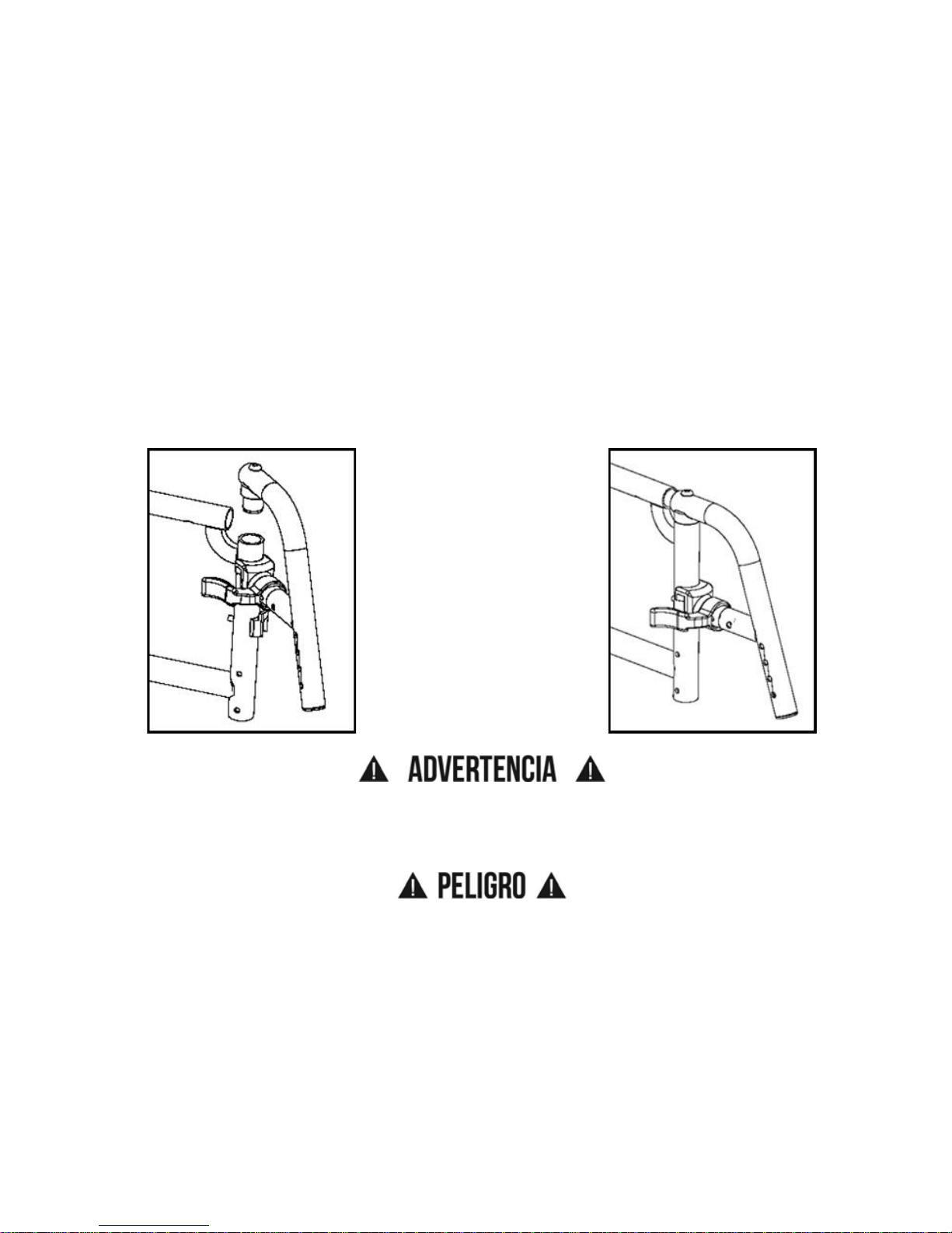
70
V. CONFIGURACIÓN Y USO
I. Sostenes
1. Instalación
a. Coloque el eje pivotante en el receptor en el tubo del marco frontal y gire hacia adentro o
hacia afuera el reposapiés (Fig. 9).
b. Gire el reposapiés para que se alinee con el marco hasta que encaje en su lugar en el blo-
que de enganche (Fig. 10).
2. Giro del reposapiés fuera
a. Presione el pestillo de liberación hacia el marco.
b. Gire el reposapiés hacia afuera o hacia adentro si lo desea.
3. Quitar
a. Para quitar el reposapiés, presione el pestillo de liberación hacia el marco.
b. Levante el reposapiés derecho hacia arriba para quitar. También puede girar el reposapiés
hacia adentro o hacia afuera antes de levantarla.
ADVERTENCIA: Asegúrese siempre que los sostenes están bloqueados en su lugar antes de
usarlos o andar en la silla de ruedas. El no hacerlo puede resultar en una caída o la pérdida de
control y puede causar lesiones graves o la muerte.
PELIGRO: Nunca intente levantar la silla por los sostenes, que pueden romper o desconectar lo
que resulta en una caída o la pérdida de control y pueden causar lesiones graves o la muerte.
Fig. 9
Fig. 10
Page 73

71
V. CONFIGURACIÓN Y USO
J. Apoyapiernas Swing Away con Pestillo de 4
Posiciones
1. Instalación
a. Colocar el sillín pivotante swing away dentro del receptor del
tubo anterior del cuadro (Fig. 11:A).
b. Rotar el apoyapies para que se alinee con el cuadro y se blo-
quee en su sitio (Fig. 11:B).
2. Abatiendo el Apoyapies
a. Hale o empuje el pestillo de extracción.
b. Rote el apoyapies hacia afuera o hacia adentro según su necesi-
dad.
3. Extracción
a. Para extraer el apoyapies, hale o empuje el pestillo de
extracción.
b. Hale el apoyapies hacia arriba para extraerlo. Usted también
puede abatir el apoyapies hacia adentro o hacia afuera antes de
halarlo hacia arriba.
4. Rotar (Fig. 12)
El pestillo de 4 posiciones posee ocho configuraciones posibles, cuatro con la curva de la palanca
hacia afuera y cuatro con la curva de la palanca hacia adentro. Ver Fig. 13 para ver las
configuraciones posibles.
a. Para rotar el pestillo de 4 posiciones, retire el tornillo utilizando una llave Allen de 3mm,
mientras la bandeja se halla todavía en la silla (el resorte debe estar colocado para extraer y
reinsertar el tornillo y al dejar la bandeja en la silla se mantiene el resorte instalado). Asegure
que la tuerca no caiga.
b. Rotar el pestillo de 4 posiciones en la orientación
deseada y volver a insertar el tornillo con la llave
Allen de 3mm. Asegure que la tuerca permanece
en su posición mientras ajusta el tornillo. No ajuste
demasiado el tornillo o el mecanismo se invalidará.
NOTA: Para regresar el pestillo de 4 posiciones retire el
mismo tornillo, pero deberá retirar la bandeja de su sitio.
Una vez retirada, deslice el pestillo hacia afuera, déle la vuelta y vuelva a instalarlo. Asegure que el
resorte está instalado presionando y sosteniendo el botón del pestillo, la tuerca debe permanecer
en su posición mientras se instala el tornillo.
NOTA: Usted no podrá obtener la posición in-line con la opción de apoyapies Pro ELR.
Fig. 11
A
B
Tornillo
Tuerca
Fig. 12
Ocho
Configuraciones
Posibles
Palanca
Hacia
Afuera
Palanca
Hacia
Adentro
Posición
Estandar
Fig. 13
Page 74
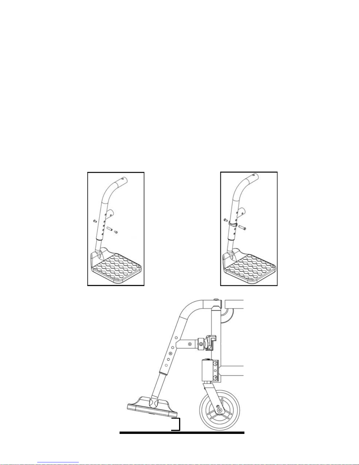
72
V. CONFIGURACIÓN Y USO
K. Tubos de Extensión
1. Ajuste
a. Retire los tornillos de montaje de cada lado del tubo del sostén.
b. Deslice el tubo de extensión del reposapiés a la altura deseada.
c. Alinee los agujeros y reensamble los sujetadores en el agujero deseado a través del sostén
y el tubo de extensión.
d. Siga el mismo procedimiento en el lado opuesto (Fig. 14 & 15).
En el punto más bajo, reposapiés deben ser de al menos 2½ pulgadas del suelo. Si se establece
demasiado bajo, pueden "atrapar" a obstáculos que se puede esperar de encontrar en un uso
normal. Esto puede provocar que la silla se detenga súbitamente y se vuelque hacia adelante (Fig.
16).
Para Evitar un Tropezón o una Caída Cuando Usted Transfiere:
a. Asegúrese de que sus pies no queden atrapados en el espacio entre los reposapiés.
b. Evite cargar el peso sobre los reposapiés ya que la silla podría voltearse hacia adelante.
Fig. 15
Fig. 14
Fig. 16
2.5"
Page 75
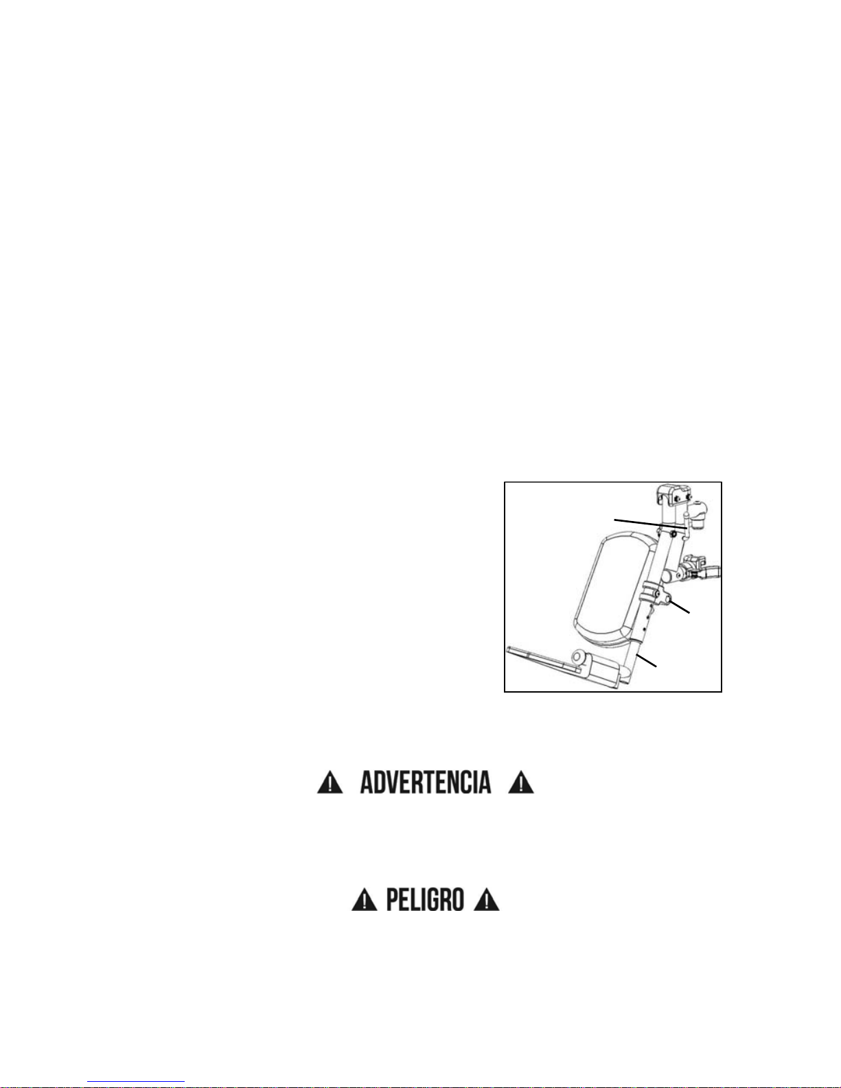
73
V. CONFIGURACIÓN Y USO
L. Elevar Reposapiernas
1. Instalación
a. Coloque rabadilla abatible pivotante en el receptor en el tubo del marco frontal con el
reposapiés hacia adentro o hacia afuera de la estructura. Similar a abatir el reposapiés representado en la Fig. 9 y Figure 10 en la página 70.
b. Gire el reposapiés para que se alinee con el marco hasta que encaje en su lugar en el blo-
que de enganche.
2. Quitar
a. Para quitar el reposapiés, presione el pestillo de liberación hacia el marco.
b. Gire el reposapiés hacia afuera y levantar.
3. Ajuste Del Tubo de Extensión
a. Retire el perno de montaje que está roscado en el tubo de apoyo para las piernas en el cen-
tro de la abrazadera de la almohadilla (Fig. 17:C). En algunas circunstancias, este perno se
puede insertar en el tubo por debajo del soporte de pivote.
b. Deslice el tubo de extensión del reposapiés a la altura deseada.
c. Alinee los agujeros y reemplace el perno a través del tubo de reposapiernas y el tubo de
extensión.
d. Siga el mismo procedimiento en el lado opuesto.
4. Ajuste Del Ángulo
a. Para levantar, levante la parte trasera del tubo de exten-
sión (Fig. 17:A). La varilla se desliza a través del trinquete en esta dirección. Deténgase en la posición
deseada.
b. Para bajar, mantener firmemente la pierna de detrás del
tubo de extensión (Fig. 17:A). Tire hacia delante en la
palanca (Fig. 17:B) y mientras sujeta la palanca, levante
el soporte para las piernas. Liberación de la palanca,
causará que el reposapiernas se bloqueo en su
posición.
Para Evitar Un Tropezón o Una Caída Cuando Usted Transfiere:
a. Asegúrese de que sus pies no queden atrapados en el espacio entre los reposapiés.
b. Evite cargar el peso sobre los reposapiés que la silla podría volcar hacia adelante.
ADVERTENCIA: En el punto más bajo, reposapiés deben ser de al menos 2 ½ pulgadas del
suelo. Si se establece demasiado bajo, pueden "atrapar" a obstáculos que se puede esperar de
encontrar en un uso normal. Esto puede provocar que la silla se detenga súbitamente y se
vuelque hacia adelante.
PELIGRO: Nunca intente levantar la silla por los sostenes, que pueden romper o desconectar lo
que resulta en una caída o la pérdida de control y pueden causar lesiones graves o la muerte.
Fig. 17
B
C
A
Page 76

74
V. CONFIGURACIÓN Y USO
M. Apoyapiernas Elevable Pro
Instalación
NOTA: El Pro ELR es montado sobre la silla de la misma manera que una bandeja swing away.
1. Coloque el sillín del pivote swing away dentro del receptor en el tubo anterior del cuadro con el
apoyapiernas mirando hacia adentro o hacia afuera del cuadro.
2. Rotar el apoyapiernas para que se alinee con el cuadro hasta que se trabe en su sitio.
Ajustando la Altura de la Almohadilla de Pantorrilla
1. Aflojar la tuerca (Fig. 18:A) utilizando una llave de 10mm.
2. Deslice la almohadilla de pantorrilla hacia arriba o hacia
abajo hasta lograr la ubicación deseada. Vuelva a ajustar la
tuerca.
Ajustando la Profundidad de la Almohadilla de Pantorrilla
1. Retire el tornillo (Fig. 18:B) y tuerca (Fig. 18:C) en el brazo
de almohadilla de pantorrilla utilizando una llave Allen de
5mm y una llave de 13mm.
2. Seleccione la ubicación deseada en base a los 4 orificios y vuelva a instalar el tornillo y la
tuerca.
Ajustando el Largo del Apoyapies
1. Afloje el tornillo (Fig. 19:A) con una llave Allen de 4mm.
2. Deslice el tubo de extensión hacia adentro o hacia afuera
para obtener el largo deseado y asegure ajustando el
tornillo.
Ajustando Altura de Rodilla
1. Utilizando dos llaves tubulares de 10mm, afloje las
dos tuercas (Fig. 20:A) en la cubierta.
2. Ajuste la altura de rodilla al seteo deseado.
3. Vuelva a ajustar las dos tuercas (Fig. 20:A) luego de
obtener la altura deseada.
Usos
1. Para elevar el Pro ELR, levante el tubo de
apoyapiernas (Fig. 21:A) al ángulo de elevación
deseado.
2. Para bajar el Pro ELR, presione y sostenga el bloqueo de la palanca (Fig. 21:B) mientras
empuja el tubo del apoyapiernas (Fig. 21:A) hacia abajo.
NOTA: Retire el Pro ELR de la silla o retire el peso del Pro ELR
mientras lo baja, para evitar una caída inesperada cuando se
presiona el bloqueo de la palanca.
NOTA: La almohadilla de pantorrilla puede abatirse hacia afuera
para liberar la parte anterior de la silla en caso de transferencias.
Extracción
1. Para remover el apoyapiernas, hale o empuje el pestillo de
extracción.
2. Levante el apoyapiernas hacia arriba para extraer. Usted
también puede abatir el apoyapiernas hacia adentro o hacia
afuera antes de levantarlo.
Fig. 18
A
B
C
Fig. 19
A
1 ½”
range of
motion
Fig. 20
A
1½" de
rango de
movimiento
Fig. 21
A
B
Page 77

75
V. CONFIGURACIÓN Y USO
N. Respaldo de Altura Ajustable
1. Ajuste de Altura (Fig. 22)
a. En los marcos laterales traseros hay agujeros de 1 pulgada de
diferencia que sujetan los tubos posteriores.
b. Retire los dos tornillos de cada marco lateral trasero.
c. Después de seleccionar la altura deseada, reemplace tornillo a
través del marco y el tubo del respaldo.
d. En la parte inferior de la tapicería está una lengüeta y una brida
de plástico. Ejecute el tornillo del marco a través de la brida de
plástico o si no hay suficiente espacio utilice el tornillo adicional
que se envió con el tapizado del respaldo.
e. Apriete y elimine cualquier exceso de la brida de plástico.
O. Respaldo de Profundidad Ajustable
1. Ajuste del Ángulo
a. Para ajustar los ángulos de respaldo quitar el tornillo M6 y la
tuerca (Fig. 23:A) en ambos lados que pasan por la placa trasera
y la parte posterior del tubo.
b. Gire la manija de empuje (Fig. 23:B) hacia delante o hacia atrás
hasta que haya alcanzado el ángulo deseado.
c. Vuelva a colocar los dos tornillos M6 a través de la placa trasera
en los barriles con rosca.
d. Repita en el otro respaldo.
2. Plegable
a. Para plegar los respaldos empujar la palanca (Fig. 23:C) hacia la
parte delantera de la silla. El respaldo girará y pliegue hacia adelante. Repita con el otro
lado.
3. Ajuste de Profundidad
a. Para cambiar la profundidad de su Catalyst 5 o Spark quite el
tornillo y la tuerca a cada lado de la placa trasera en la
posición (Fig. 24:E).
b. Retire el tornillo y la tuerca de cada lado de la placa de la cer-
radura (Fig. 24:F). El montaje del respaldo (Fig. 24:D) puede
entonces ser colocado de nuevo en un agujero disponible en
del marco lateral.
c. Después de reposicionamiento, sustituya los tornillos y tuer-
cas en la placa lateral a través de la ubicación (Fig. 24:E) y la
placa de la cerradura (Fig. 24:F).
Fig. 22
Fig. 23
B
C
A
Fig. 24
D
E
F
Page 78

76
V. CONFIGURACIÓN Y USO
P. Espaldar Semi-Plegable Catalyst
ADVERTENCIA: Siempre cuente con un técnico calificado para setear su silla de ruedas con
los accesorios que planea utilizar diariamente. Los cambios en su manera de sentarse ó los
cambios en su peso requieren que su silla sea reajustada por un técnico calificado. Siempre utilice
anti-vuelcos hasta acostumbrarse a cualquier cambio en el seteo de su silla. El no cumplir con las
instrucciones arriba mencionadas podría resultar en lesiones severas o muerte.
Uso (Fig. 25)
1. Presione la palanca de extracción hacia los caños del espaldar mientras pliega los caños
del espaldar hacia abajo.
2. Levante el caño del espaldar hasta que haga "click" o se bloquee, para regresarlo a su
posición operativa.
PELIGRO: No coloque o cuelgue objetos de los caños del espaldar. El hacer esto podría
resultar en una liberación accidental de la palanca de plegado en el espaldar semi-plegable, lo
cual podria resultar en caída o pérdida de control con lesiones severas o muerte.
PELIGRO: No utilice la silla si el caño del espaldar no se halla en posición operativa. El hacer
esto podría resultar en una caída y lesiones severas o muerte.
Ajuste de Altura
Ver la sección de Espaldar con Altura Ajustable en el manual del usuario.
Fig. 25
Plegado hacia abajo
Plegado hacia arriba
Page 79

77
V. CONFIGURACIÓN Y USO
Q. Espaldar Reclinable Catalyst
ADVERTENCIA: La altura del espaldar, ángulo del espaldar, profundidad de asiento, ángulo de
reclinación, altura de asiento, tamaño/posición de ruedas posteriores, tamaño/posición de
casters anteriores y cualquier agregado de peso en la parte posterior de la silla -tales como
accesorios, morrales y tubos de oxígeno- todos se relacionan y afectan la estabilidad de la silla de
ruedas. Cualquier ajuste o modificación a uno o más de los items listados más arriba, puede
disminuir la estabilidad de la silla de ruedas. Tenga cuidado cuando realice modificaciones a los
items mencionados. Consulte con un técnico calificado cuando ajuste la altura del espaldar, el
ángulo del espaldar, la profundidad del asiento, la altura del asiento, tamaño/posición de las
ruedas posteriores y tamaño/posición de los casters. Los ajustes inapropiados pueden resultar en
lesiones severas.
Notas para la Operación del Espaldar Reclinable
1. Luego de realizar cualquier ajuste al sistema, asegúrese de que todo el hardware es ajustado
adecuadamente.
2. Siempre asegure que la silla de ruedas es estable en la posición de reclinación total.
Dependiendo del ángulo del espaldar, la posición de reclinación total será de 65° y es relativa
a la posición erguida total. La posición erguida total se mide como 0°.
3. Siempre trabe las ruedas cuando recline o incline para asegurar máxima seguridad del
paciente.
4. Antes de utilizar el espaldar reclinable, asegure que los anti-vuelcos están ajustados
apropiadamente para asegurar que la silla de ruedas permanezca estable durante su uso. Ver
instrucciones de Anti-Vuelcos en página 88.
PELIGRO: Bascular o reclinar la silla más allá de nivel, aumenta grandemente el riesgo de caida
de la silla, lo cual puede resultar en lesiones severas o muerte.
Reclinación / Inclinación
1. Destrabe el sistema antes de realizar ajustes de
reclinación ó inclinación, extrayendo el pin de bloqueo
(Fig. 26:A) del orificio de bloqueo (Fig. 26:B) a cada lado
del gatillo de reclinación.
2. Asegure que las ruedas se hallan bloqueadas y que la
silla se halla en una superficie nivelada.
3. Sostenga las manijas firmemente y lentamente suelte
ambos gatillos de reclinación (Fig. 26:C) al mismo tiempo
para liberar los cilindros de gas. Esto le permitirá ajustar
la posición del espaldar de la siguiente manera:
a. Reclinación - para abrir el ángulo del espaldar relativo
al cuadro de asiento, ó reclinar aplicando fuerza hacia
abajo sobre los resortes a gas.
b. Inclinación - regrese a la posición erguida aplicando fuerza hacia arriba y empujando el
espaldar hacia la parte anterior de la silla de ruedas.
4. Once desired backrest recline angle has been achieved, slowly release both reclining triggers.
5. To lock the system, insert the locking pin (Fig. 26:A) into the locking pin hole (Fig. 26:B). It is
recommended that you always lock both reclining backrest triggers when you are done
positioning the patient.
A
A
B
C
C
B
Fig. 26
Page 80

78
V. CONFIGURACIÓN Y USO
Q. Espaldar Reclinable Catalyst
Mover el Sistema de Reclinación a lo Largo del Cuadro Posterior
ADVERTENCIA: Retire al paciente de la silla de ruedas antes de realizar este ajuste. El no hacer
esto podria resultar en lesiones severas o muerte.
1. Dependiendo de donde se hallan instaladas las placas de montaje en el cuadro, usted puede
ajustar el espaldar reclinable de la siguiente manera a lo largo del cuadro posterior: 1" más
corto, 2" más corto ó 2" más profundo.
2. Utilizando una llave Allen de 4mm y una llave de 10mm, extraiga los tornillos de cabeza plana
(Fig. 27:A), los sillines (Fig. 27:B) y las tuercas hexagonales M6 (Fig. 27:C).
3. Mueva el ensamble a la ubicación deseada a lo largo del cuadro posterior.
4. Vuelva a colocar los sillines entre la placa y el costado posterior del cuadro (Fig. 27:B), inserte
los tornillos de cabeza plana (Fig. 27:A) y coloque y ajuste las tuercas hexagonales M6 (Fig.
27:C) hasta que se hallen firmemente ajustadas.
5. Repita en el lado opuesto.
C
B
B
A
Fig. 27
Page 81

79
V. CONFIGURACIÓN Y USO
R. Instalación y Extracción de la Rueda (Opcional en Algunos Modelos)
1. Instalación de las Ruedas:
a. Oprima el botón de liberación del eje en el eje para per-
mitir que el seguro se libere. Tome nota de la diferencia
entre la posición extendida y deprimida del botón de liberación del eje y su efecto sobre el sistema de seguridad
en el otro extremo del eje (Fig. 28).
b. Inserte el eje en la caja del rodamiento de la rueda si es
separada.
c. Empuje el botón de liberación rápida de nuevo y deslice
el eje en la manga del eje (Fig. 28).
d. Suelte el botón para bloquear el eje en la manga. Si el
botón de liberación no se extiende totalmente y el
sistema de seguridad no se movió en la posición de bloqueo después de soltar el botón, la
longitud del eje debe ser ajustado (Fig. 29).
2. Ajuste de Ejes
a. Para ajustar el eje necesitará una llave de 19mm para
girar las tuercas exteriores del eje.
b. Usted también necesitará una llave de 11mm para
mantener los rodamientos de bolas en el extremo
opuesto del eje, y evitar que el eje gire.
c. Cuando se instala la rueda, si el eje no funciona para
bloquear, aflojar la tuerca del eje hasta que se bloquee y
el eje pueda moverse dentro y fuera ligeramente una
vez cerradas. Si se bloquea el eje, pero se mueve dentro y fuera ligeramente, proceden a d.
d. Girar la tuerca del eje hacia la izquierda hasta que
quede bien apretado luego gire la tuerca del eje hacia la derecha 1/3 de vuelta a la vez.
Revise para ver si se ajusta adecuadamente después de cada una de 1/3 de vuelta.
Cuando se ajusta adecuadamente no debería haber ningún movimiento perceptible del eje
de entrada y salida de la manga, pero el botón de liberación del eje debe ser fácil de empujar adentro.
Revisar y entender Instalación y Extracción de la Rueda Sección R. antes de intentar un ajuste
del eje!
3. Instalación y Extracción de la Rueda
a. Sostenga la rueda cerca al buje y empujar adentro el botón en el extremo exterior del eje.
b. Mientras mantiene presionado el botón jale la rueda y el eje fuera de la manga del eje.
PELIGRO: Asegúrese de que el botón pulsador está completamente extendido y el sistema de
seguridad en el interior de la silla están totalmente ocupado antes de utilizar la silla de ruedas. El
no hacerlo puede resultar en la rueda de caerse y causar lesiones graves o la muerte.
Fig. 28
Eje
Manga de eje
Botón de extracción de eje
Fig. 29
Rodamientos
de bolas
Page 82

80
V. CONFIGURACIÓN Y USO
S. Catalyst 5, 5Ti y Spark
1. Centro de Gravedad (Fig. 30)
Moviendo la manga del eje dentro de la placa del eje cambia la
distribución del peso entre las ruedas pivotantes y las ruedas traseras.
Como se mueve hacia adelante más del peso está en la rueda trasera.
Esto quita peso a las ruedas delanteras y puede hacer que sea más fácil
de maniobrar la silla de ruedas. También hace que la silla de ruedas sea
menos estable y hace más fácil volcar para atrás. Cuanto más atrás el
eje, lo más estable que se convierte la silla. Ki Mobility recomienda
trabajar con su proveedor autorizado de Ki Mobility al considerar hacer
este ajuste.
ADVERTENCIA: Siempre se debe utilizar dispositivos antivuelco al intentar usar su silla
después de hacer ajustes a la colocación del eje. El no hacerlo podría causar que se vuelque o
perder el control y causar lesiones graves o la muerte.
PELIGRO: Ajustar la manga del eje demasiado hacia adelante puede causar que la silla se
voltee hacia atrás, lo que resulta en una caída o pérdida del control y provocar lesiones graves o la
muerte.
2. Inclinación de las Ruedas (Fig. 31)
Agregar inclinación a una placa de eje proporciona una estabilidad
más lateral a la silla de ruedas debido a la mayor anchura entre la
base de ruedas. La inclinación adicional hace girar más fácil la silla
de ruedas y puede mejorar el acceso a los aros de empuje.
Inclinación o camber de las ruedas se selecciona durante el
processo de pedido. No importa cuál sea la inclinación que
originalmente se estableció para la silla de ruedas se puede
cambiar. Para ajustar la inclinación quite los tornillos de la placa del
eje. Si se desea mayor inclinación se debe añadir arandelas y cada
arandela representa 1 grado. No agregue más de 6 arandelas. Si
desea menos inclinación quite 1 arandela por cada grado que
desea eliminar. Después de colocar el número deseado de
arandelas vuelva a instalar la placa de eje y los tornillos. Haga lo
mismo con la placa del eje en el lado opuesto de la silla de ruedas.
Fig. 30
Placa de eje
Manga de eje
Fig. 31
Inclinación de las arandelas
Page 83

81
V. CONFIGURACIÓN Y USO
S. Catalyst 5, 5Ti y Spark
3. Ajuste de Distancia Entre Ejes (Fig. 32)
La manga que sujeta el eje es ajustable dentro y fuera. El ajuste
de esta manga permite al usario mover las ruedas más cerca o
más lejos de la placa del eje aumentando o disminuyendo de este
modo la anchura total. El aumento de la anchura total mejorará la
estabilidad de un lado a otro, pero puede hacer más difícil para
caber a través de puertas. La disminución de la anchura total
puede mejorar la accesibilidad. Al disminuir la anchura total,
asegúrese de que usted no crea una condición de que las ruedas
se frota en reposabrazos o en otras partes de la silla.
a. Afloje las tuercas y gire la manga del eje hacia adentro o
afuera si lo desea (Fig. 32:A). Cuente el número de hebras
mostrando y repita en el lado opuesto.
b. Vuelva a apretar las tuercas.
4. Ajuste de Altura Trasera del Asiento
La altura del asiento trasero se puede ajustar moviendo la placa del eje vertical en los orificios
previamente taladrados del marco. Este permite un ajuste de la altura del asiento vertical de 4".
NOTA: Un ajuste de la rueda pivotante se debe hacer para que se corresponda con cualquier
cambio en la altura del asiento. Vea la sección Z. Horquillas de la Rueda Pivotante.
Fig. 32
Page 84

82
V. CONFIGURACIÓN Y USO
T. Catalyst 5Vx
1. Centro de Gravedad (Fig. 33):
Mover la placa del eje del marco cambia el centro de gravedad cambiando la
distribución del peso entre las ruedas pivotantes y las ruedas traseras. Como se
mueve hacia adelante más del peso está en la rueda trasera. Esto quita peso a las
ruedas delanteras y puede hacer que sea más fácil de maniobrar la silla de ruedas.
También hace que la silla de ruedas sea menos estable y hace más fácil volcar para
atrás. Cuanto más atrás este el eje, hace más estable la silla. Ki Mobility
recomienda trabajar con su proveedor autorizado de Ki Mobility al considerar hacer
este ajuste.
ADVERTENCIA: Siempre se debe utilizar dispositivos antivuelco al intentar usar su silla
después de hacer ajustes a la colocación del eje. El no hacerlo podría causar que se vuelque o
perder el control y causar lesiones graves o la muerte.
PELIGRO: Ajustar la placa del eje demasiado hacia adelante puede causar que la silla se voltee
hacia atrás, lo que resulta en una caída o pérdida del control y provocar lesiones graves o la
muerte.
2. Ajuste de Altura Trasera del Asiento (Figure 34):
La altura del asiento se puede ajustar moviendo la manga del eje
vertical en los agujeros pre-perforados en la placa del eje. Este ajuste
permite un ajuste de altura vertical del asiento de 5".
NOTA: Un ajuste de la rueda pivotante se debe hacer para que se
corresponda con cualquier cambio en la altura del asiento (Vea la
sección: T. Horquillas de la Rueda Pivotante).
3. Ajuste de Distancia Entre Ejes (Fig. 34)
La manga que sujeta el eje es ajustable hacia adentro y afuera. El
ajuste de este casquillo permite al usuario mover las ruedas más
cerca o más lejos de la placa del eje aumentando o disminuyendo de
este modo el ancho total. El aumento del ancho total mejorará la
estabilidad de un lado a otro, pero puede hacer más difícil el acceso a
través de puertas. La disminución del ancho total puede mejorar la
accesibilidad. Al disminuir del ancho total, asegúrese que las ruedas no queden rozando los
reposabrazos o en otras partes de la silla.
a. Afloje las tuercas y gire la manga del eje hacia adentro o afuera si lo desea (Fig. 34). Cuente
el número de hebras que muestran y repita en el lado opuesto.
b. Vuelva a apretar las tuercas.
Fig. 33
Fig. 34
Page 85
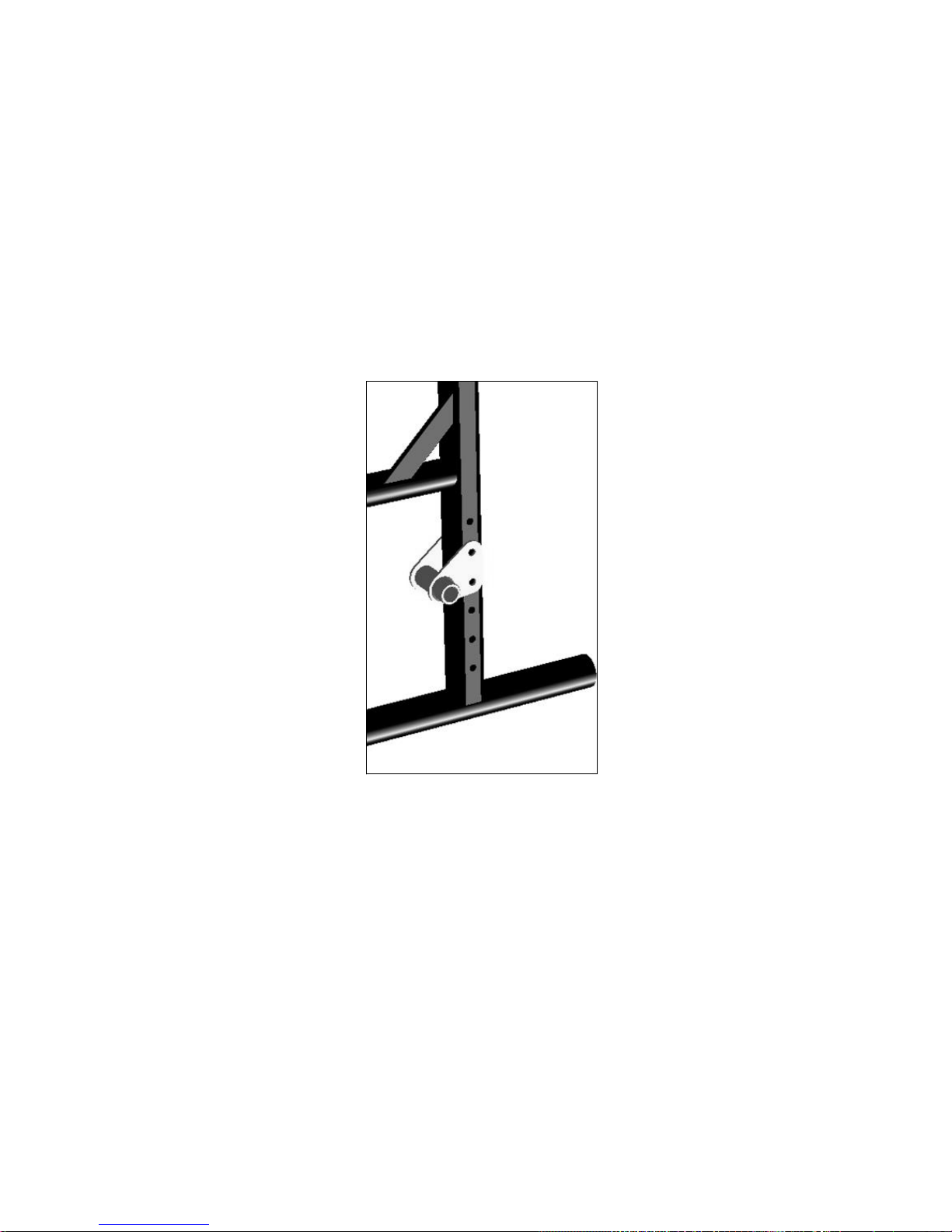
83
V. CONFIGURACIÓN Y USO
U. Catalyst 4 y 4C
1. Ajuste de Altura Trasera del Asiento (Fig. 35)
La altura trasera del asiento se puede ajustar moviendo la placa del eje vertical en los orificios
pretaladrados en el marco.
a. Retire los 2 tornillos de cabeza hexagonales con una llave de 10mm.
b. Vuelva a colocar la placa del eje hacia arriba o hacia abajo en incrementos de 1" en función
del cambio que desea hacer. Este ajuste permite un rango de ajuste de altura del asiento
vertical total de 5".
NOTA: Un ajuste de la rueda pivotante se debe hacer para que se corresponda con cualquier
cambio en la altura del asiento (Vea la Sección: Z. Horquillas de la Rueda Pivotante).
Fig. 35
Page 86

84
V. CONFIGURACIÓN Y USO
V. Spark - Marco Plegable
1. Marco Plegable
Antes de intentar doblar el marco eliminar cualquier sistema de asientos que se adjunta. También
levante hacia arriba o remover cualquier reposapiés.
a. Levante hacia arriba de la correa (Fig. 36:A). Esto desenganchará soportes de los refuerzos
transversales (Fig. 37:C) de ganchos de asiento.
b. Para volver a abrir el marco empuje hacia abajo de los refuerzos transversales (Fig. 36:B)
hasta que los soportes del refuerzo transversal (Fig. 37:C) se han enganchado por completo con los ganchos de asiento.
Fig. 37
C
Fig. 36
A
B
Page 87

85
V. CONFIGURACIÓN Y USO
W. Spark - Ajustar Ancho del Marco
1. Ajustar Ancho del Marco
Para cambiar la anchura del marco:
a. Quite los pernos que conectan los refuerzos transversales y las extensiones de los refuerzos
transversales (Fig. 38:A) en ambos lados de la estructura.
NOTA: Tenga en cuenta cual agujero el perno (Fig. 39:B) está utilizando en el soporte superior del
pivote (Fig. 39:C).
b. Retire el perno (Fig. 39:D) del centro de refuerzos transversales.
c. Deslice extensiones de los refuerzos transversales dentro o fuera para llegar a la anchura
general deseada. Cada marco está disponible con 3 anchuras de asiento en incrementos
de 1".
Para medir la anchura, tomar una medida desde el exterior del marco del asiento por un lado y la
parte exterior del marco del asiento en el otro lado.
d. Después de localizar el ancho deseado deslice el perno (Fig. 39:B) a través de los refuerzos
transversales y las extensiones del refuerzo transversal en ambos lados. Después localice el
orificio central que corresponda. Si el tornillo está en el orificio del medio de la extensión
entonces localice el orificio central en el medio, ext.
X. Tela de Tapicería
1. Debe reemplazar inmediatamente el asiento y tapizado del respaldo que ha desgastado o si
hay síntomas de defecto. Si no lo hace, el asiento o el respaldo pueden fallar.
2. El material del asiento se debilitará con el tiempo. Busque deshilache, puntos finos, o
estiramiento de los tejidos, especialmente en los bordes y costuras. Esto debe hacerse
semanalmente.
3. La acción repetida de la transferencia a la silla de ruedas va a debilitar el material del asiento y
da lugar a la necesidad de revisar y reemplazar el asiento más a menudo.
4. Tenga en cuenta que el lavado o el exceso de humedad se reduce el retardo al fuego de la
tela.
5. Póngase en contacto con su proveedor de silla de ruedas si usted tiene preocupaciones
acerca de su seguridad o el respaldo, o siente que necesita ser reemplazado.
ADVERTENCIA: El incumplimiento de estas instrucciones puede resultar en daños a su silla de
ruedas, una caídad o pérdida del control y provocar lesiones severas al usuario o otras personas.
Fig. 38
A
Fig. 39
D
C
B
Page 88

86
V. CONFIGURACIÓN Y USO
Y. Seguros de las Ruedas
La sillas de ruedas Catalyst y Spark se envían con uno de varios tipos diferentes de frenos de
ruedas pre-instalado.
• Empujar para Asegurar
• Jale para Asegurar
• Empujar para Asegurar (Montaje Rasante)
• Tipo Tijera
El conjunto de abrazadera funciona de la misma para
todos los seguros de las ruedas.
a. Utilice una llave Allen de 5mm, gire uno de los tornil-
los de la abrazadera hasta que este flojo (menos de
una vuelta).
b. Repetir el mismo proceso con el segundo de los
dos tornillos de modo que la abrazadera se puede
ajustar en el marco.
c. Ajustar la abrazadera hacia la rueda trasera para,
cuando participan, el seguro de las ruedas comprime la llanta y evita cualquier movimiento de la rueda (Fig. 40).
d. Asegúrese de que los brazos del seguro de la rueda
encajen en las llantas al menos 1/8 de pulgada
cuando está bloqueado. Si usted no lo hace, los
seguros no pueden trabajar (Fig. 41).
e. Vuelva a apretar los tornillos.
Abrazaderas de seguro de las ruedas requieren un par
de apriete de 100 pulg./lbs.
Seguros de las ruedas traseras NO están diseñados
para reducir la velocidad o parar una silla de ruedas en
movimiento. Úsalos sólo para mantener las ruedas
traseras de rodar cuando su silla esté detenida por
completo.
• NUNCA use seguros de las ruedas traseras para desacelerar o detener su silla cuando se
está moviendo. Si lo hace, puede causar que usted vire fuera de control.
• Para evitar que las ruedas traseras de rodar, siempre active ambos seguros de las ruedas
traseras cuando se transfiere desde o hacia su silla.
• Baja presión en un neumático trasero puede hacer que el seguro de las ruedas de ese lado
pueda deslizarse y puede permitir que la rueda gire cuando usted no lo espera.
• Asegúrese de que los brazos del seguro de la rueda encajen en las llantas al menos 1/8 de
pulgada cuando está bloqueado. Si usted no lo hace, los seguros no pueden trabajar.
PELIGRO: La falta de lectura o el cumplimiento de estas instrucciones puede resultar en una
caída o pérdida del control y provocar lesiones severas al usuario o otras personas.
Fig. 40
Fig. 41
Page 89

87
V. CONFIGURACIÓN Y USO
Z. Horquillas de la Ruedas Pivotante
Las horquillas de las ruedas permiten la intercambiabilidad de ruedecillas y el ajuste de la altura
delantera del asiento (Fig. 42).
Para ajustar:
a. Afloje la tuerca del eje y retire el eje.
b. Puede recolocar el eje y las ruedas hacia arriba o hacia abajo en
incrementos de ½" para cambiar la altura del asiento delantero.
c. Reemplace el eje y apriete la tuerca.
Si se desea una rueda pivotante diferente, determinar la diferencia de altura
entre la nueva y la vieja rueda (para mantener la altura del asiento: 1" más
alto del tamaño de la rueda ajusta hasta 1 posición del agujero).
Si ha cambiado la altura delantera del asiento usted debe cuadrar el
alojamiento de la rueda pivotante (Vea siguiente Instruccion).
AA. Ajuste de Angulo de Horquilla
El alojamiento de la rueda pivotante debe estar siempre en un ángulo de 90° al piso
(perpendicular al suelo). Esto se ajusta mediante un elemento de fijación especial y una tuerca
excéntrica (Fig. 43).
a. Para cambiar el ángulo del alojamiento de la rueda, lo mejor
es colocar la silla sobre una superficie plana.
b. Quite el perno de la parte interior del marco.
c. Coloque una escuadra contra la mesa y la parte frontal del
alojamiento de la rueda para realinear el alojamiento.
d. Empuje los pernos de nuevo a través del marco.
e. Girar las tuercas excéntricas de forma independiente hasta
que encajan tanto en el perno y dentro de la ranura del alojamiento de la rueda.
f. Vuelva a apretar los dos pernos asegurando lentamente que
el alojamiento sigue siendo cuadrado.
g. Repita el proceso para la otra rueda.
Desempeño de Carcasa del Caster
a. Levante la cubierta protectora (Fig. 43:A).
b. Localice los dos tornillos de cabeza hueca (Fig. 43:D). Utili-
zando una llave Allen de 5mm, afloje cada tornillo dos vueltas completas.
c. Localice el Tornillo de Ajuste (Fig. 43:B). Utilizando una llave
Allen de 5mm, gire en sentido horario para mover la horquilla
de caster hacia adelante o en sentido anti-horario para
mover la horquilla del caster hacia atras, para lograr un
ángulo de 90° con respect al piso.
d. Utilizando una escudra contra el caster (Fig. 43:C), asegure
que los mismos están posicionados perpendiculars al suelo.
Una vez logrado ésto, vuelva a ajustar los tornillos de cabeza
hueca (Fig. 43:D) hasta que estén bien firmes.
e. Vuelva a colocar la cubierta protectora (Fig. 43:A). Repita en el lado opuesto.
Fig. 42
Fig. 43
Estándar
Desempeño
A
B
C
D
Page 90
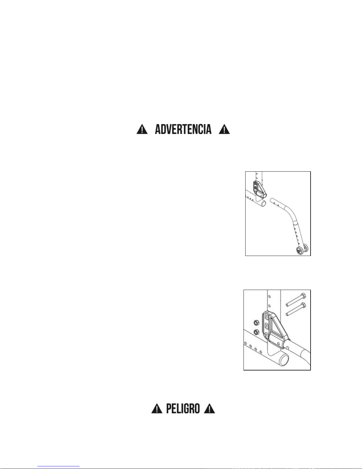
88
V. CONFIGURACIÓN Y USO
BB. Tubos Contra Volcaduras (Opcional)
Tubos antivuelco ayudan a evitar que su silla de ruedas vuelque hacia atrás. Cuando se ajusta
adecuadamente proporcionan un aumento significativo en la estabilidad posterior. Su estabilidad
puede verse afectada cuando atraviesa un terreno irregular, una rampa, pendiente o en otra
superficie que cambia su relación con la gravedad. Su estabilidad puede verse afectada también
por otras fuerzas que actúan sobre usted y su silla de ruedas, como alguien que empuja hacia
abajo o apoyándose en sus manijas u otras partes de su silla. Esto puede ocurrir incluso a los
usarios de silla de ruedas con mayor experiencia. La gente en su entorno no entiende
necesariamente que están impactando su estabilidad.
ADVERTENCIA: Ki Mobility recomienda firmemente el uso de tubos contra volcaduras!
Tubos contra volcaduras deben ser usados en todo momento. Ya sea recorriendo un terreno
irregular o sentado en una habitación llena de gente, lo inesperado puede ocurrir y su peso puede
cambiar dramáticamente provocando una caída que podría causar lesiones graves o la muerte.
1. Instalación de Tubos Contra Volcaduras (Fig. 44)
• Comprimir el segundo botón retén en el tubo contra volcadura
para que el botón de retención frontal se redacta en su interior.
• Inserte el tubo contra volcadura en receptor montado en marco
lateral.
• Gire el tubo contra volcadura hacia abajo hasta que las ruedas
pequeñas sean adyacentes al piso. El botón de retenida ahora
debe estar alineado con un agujero en el receptor. Suelte el
botón de reténida y se encajara con el receptor.
• Inserte segundo tubo contra volcadura de la misma forma.
2. Ajuste de la Posición del Receptor del Tubo Contra Volcadura (Fig. 45)
Sólo es necesario para ajustar su Receptor del Antivuelco si cambia de la silla. Si realiza cambios
que se requieren para ajustar la posición de su receptor, siga estos pasos:
• Retire los pernos que conectan el receptor del tubo contra
volcaduras al marco lateral de la silla.
• Los agujeros están en incrementos de 1" para que puedas
moverlo más arriba en el marco o bajo en el marco. Coloque el
corchete a la altura deseada.
• Vuelva a colocar pernos y apriete (Si los pernos también
conectan el reposabrazos y la placa del eje puede que tenga
que ponerse en contacto con su proveedor para hardware
adicional).
• Repita el procedimiento con el segundo receptor de tubo
contra volcadura. Ambos corchetes deben ser exactamente a
la misma altura.
• Reemplace los tubos contra volcadura según las instrucciones anteriores.
PELIGRO: El no leer y seguir estas instrucciones puede resultar en daños a su silla de ruedas,
una caída o pérdida del control y provocar lesiones severas al usuario o otras personas.
Fig. 44
Fig. 45
Page 91

89
V. CONFIGURACIÓN Y USO
BB. Tubos Contra Volcaduras
3. Ajustar Altura de la Extensión de la Rueda (Fig. 46)
La extensión de la rueda del tubo contra volcadura puede necesitar
ser levantada o bajada para lograr la separación adecuada de 1½"
a 2" por encima del suelo.
a. Comprime los botones de retención hasta que estén en el
interior de la pared del tubo. Esto permitirá que el tubo exterior se deslice arriba y hacia abajo en el tubo interior.
b. Deslice el tubo de extensión hacia arriba o hacia abajo hasta
conseguir la altura deseada.
c. Suelte los botones.
d. Ajuste la segunda extensión de la rueda de la misma forma.
Ambas ruedas deben ser exactamente a la misma altura.
4. Giro de los Tubos Contra Volcaduras Hacia Arriba (Fig. 47)
Puede que le resulte necesario girar los tubos contra volcaduras
hacia arriba cuando sea empujando por un cuidador, para subir
bordillos o superar los obstáculos.
a. Comprimir el segundo botón de reténida en el tubo contra vol-
cadura para que el botón de retención frontal se redacta en su
interior.
b. Mantén pulsado el botón y gire el tubo contra volcadura hacia
arriba.
c. Suelte el botón.
d. Repita con el segundo tubo contra volcadura.
e. Vuelva a poner los tubos contra volcadura hacia abajo a su
posición segura tan pronto como sea posible.
Fig. 46
Fig. 47
Page 92

90
V. CONFIGURACIÓN Y USO
CC. Eslinga de Asiento
Eslinga del asiento incluye una correa plegable en el asiento para ayudar a plegar la silla.
NOTA: La correa plegable de la eslinga de asiento no está diseñada como una correa de
transporte.
DD. Instalación de Cojín
a. La Catalyst y Spark fue diseñada para ser utilizada con un cojín de silla de ruedas apropi-
ado.
PELIGRO: Sentarse por largos periodos de tiempo sin un cojín de silla de ruedas apropiado
puede causar las úlceras por presión que pueden ser de naturaleza grave y causar la muerte.
b. La tapicería eslinga estándar está dotada de tiras de cierre tipo Velcro. El cojín que utilice
debe tener elementos de fijación de tipo Velcro gancho que puede involucrar el bucle de la
eslinga del asiento para mantener que el cojín no se deslice por de debajo de ti. Asegúrese
de que el cojín esté bien conectado antes de transferir o estar sentado en la silla de ruedas.
c. Una eslinga de asiento estándar no puede haber sido proporcionado con la silla. Consulte
con su proveedor de silla de ruedas si se ha proporcionado un reemplazo del mercado de
accesorios para el equipo original de eslinga. Si es así, asegúrese de seguir las instrucciones para el uso proporcionadas por el fabricante del mercado de accesorios.
ADVERTENCIA: Si no se asegura un cojín puede ocasionar que deslice hacia afuera durante el
uso o las transferencias y podría resultar en una caída o pérdida del control y provocar lesiones
graves o la muerte.
EE. Sostenedor del Tanque de Oxígeno
1. Instrucciones para el Uso:
Este soporte de tanque de oxígeno ha sido diseñado para asegurar cilindros a su silla de ruedas.
Asegúrese de que la botella está bien asentado en la parte inferior del soporte y que la abrazadera
se aprieta hasta el punto de que el cilindro no se pueda salir.
Los tanques de oxígeno pueden ser peligrosos, asegúrese de seguir todas las instrucciones para
el uso del proveedor del tanque.
PELIGRO: El incumplimiento de estas instrucciones y las instrucciones para el uso del cilindro
del proveedor de cilindros puede provocar lesiones graves o la muerte.
Page 93

91
VI. MANTENIMIENTO
A. Inspección de la Silla de Ruedas
El mantenimiento periódico y rutinario prolongará la vida de su silla de ruedas mientras mejora su
rendimiento. Reparaciones en la silla de ruedas y la sustitución de piezas debe ser realizado por
un técnico calificado de un proveedor autorizado de Ki Mobility.
1. Inspecciones Generales
a. Limpie su silla, al menos, una vez al mes. Puede que tenga que limpiar su silla con mayor
frecuencia si se opera en ambientes sucios, como un lugar de trabajo.
b. Revise para asegurarse de que todos los sujetadores estén apretados. A menos que se
indique lo contrario, los sujetadores deben apretarse a 40 in./lbs.
c. Revise Neumáticos y Ruedas Pivotantes:
• Revise el neumático para desgaste de la banda. Reemplace los neumáticos cuando la
banda de rodadura está desgastado o tiene puntos planos o grietas visibles.
• Si tiene neumáticos inflables con una espiga de válvula, comprobar la presión y ajustar a
la presión indicada en la pared lateral del neumático.
PELIGRO: Reemplace las llantas desgastadas. Los seguros de las ruedas no encajan
correctamente si usted no puede mantener la presión de aire mostrado en la pared lateral del
neumático. Esto podría resultar en una caída o pérdida del control y provocar lesiones graves o la
muerte.
d. Revise los rayos de ruedas por rayos flojos.
e. Revise sus seguros de las ruedas. Al desgastarse las llantas los seguros de las ruedas
deben ajustarse. Vea Y. Seguros de Ruedas en la página 86.
f. Revise su tapicería para desgarros o flacidez. Su tapicería está diseñada para ser apreta-
dos, ya que se estira con el tiempo. Vea X. Tela de Tapicería en la página 85.
Page 94

92
VI. MANTENIMIENTO
A. Inspección de la Silla de Ruedas
Semanal
a. Compruebe seguro de las ruedas para asegurarse de que están correctamente ajustados.
b. Compruebe manga de eje para asegurar que las tuercas de las mangas del eje están apre-
tadas.
c. Compruebe si hay rayos quebrados, doblados o sueltos.
d. Compruebe que las ruedas pivotantes puedan girar libremente.
e. Inspeccione las llantas y ruedas pivotantes para puntos de desgaste.
f. Revise neumáticos para la inflación apropiada.
Mensual
a. Inspeccione ejes de las ruedas traseras y apriete si es necesario.
b. Inspeccione los rodamientos del alojamiento de la rueda pivotante para acumulación de
cabellos y eliminar si es necesario.
c. Inspeccione seguros de las ruedas para estar seguro montaje esta apretado. Asegurarse
que seguros de las ruedas se enganchen correctamente en los neumáticos.
d. Verifique que todos los sujetadores estén ajustados y seguros.
e. Inspeccione agarres de mano para asegurarse de que no están sueltos.
f. Inspeccione el cuadro por cualquier deformidad, defecto, rotura, marca o torcedura. Esto
podría ser signo de fatiga en el cuadro, que podrían resultar en falla de la silla. Discontinúe el
uso de la silla de ruedas inmediatamente y contacte a su agente Ki Mobility autorizado.
Anualmente
a. Haga que la silla de ruedas sea comprobada y ajustada por un técnico calificado.
ADVERTENCIA: Despúes de los ajustes y antes de utilizar esta silla de ruedas, asegúrese de
que todos los sujetadores estén apretados y seguro o lesión o daño puede ocurrir.
PRECAUSIÓN: No apriete demasiado los sujetadores ya que esto podría dañar el tubo del marco.
PELIGRO: El no leer completamente estas instrucciones podría resultar en falla o pérdida del
control, causando severas lesiones o muerte al usuario o a terceros.
Page 95

93
VI. MANTENIMIENTO
B. Limpieza
1. Ejes y ruedas
a. Limpie alrededor de los ejes y ruedas semanalmente con un trapo húmedo.
b. Cabello y la pelusa se alojarán en el alojamiento de rueda pivotante. Desensamblar el aloja-
miento de rueda pivotante cada seis meses para eliminar el pelo enredado.
NOTA: No utilice WD-40 o cualquier otro aceite penetrante sobre esta silla de ruedas. Esto
destruirá los rodamientos sellados.
NOTA: No utilice ningún producto de limpieza con agentes químicos en las ruedas pivotantes o
en ruedas traseras.
2. Tapicería
a. Solo lavar a mano (lavado de la máquina puede causar daños a la tela).
b. Seque en línea solamente. NO seque a máquina, el calor de la secadora puede dañar la
tela.
ADVERTENCIA: El no leer y cumplir con estas instrucciones puede resultar en daños a su silla
de ruedas, una caída o pérdida del control y provocar lesiones severas al usuario o otras
personas.
C. Almacenamiento
a. Cuando no esté en uso, mantenga su silla en un área limpia y seca. El no hacerlo puede
resultar en que su silla se oxidada y / corroe.
b. Si su silla ha estado almacenada durante más de un par de semanas usted debe asegu-
rarse de que funciona correctamente. Usted debe inspeccionar y dar servicio si es necesario, todos los artículos en la Sección VI. A. Inspección de su silla de ruedas.
c. Si su silla ha estado almacenada durante más de dos meses, debe solicitar mantenimiento
y revisar por su distribuidor autorizado antes de usarla.
ADVERTENCIA: El no leer y cumplir con estas instrucciones puede resultar en daños a su silla
de ruedas, una caída o pérdida del control y provocar lesiones severas al usuario o otras
personas.
Page 96

94
VII. GARANTÍA
Ki Mobility garantiza el cuadro, las crucetas, las bandejas y los ejes de extración rápida de su silla
de ruedas Catalyst contra defectos en materiales y fabricación, durante la vida del comprador
original. Todas las partes y componentes de la silla de ruedas están garantizados contra defectos
de materiales y fabricación por un año desde la fecha de compra del primer usuario.
Limitaciones de la Garantía
1. No garantizamos:
a. Artículos de desgaste: Tapicería, neumáticos, almohadillas de reposabrazos, tubos, reposa-
brazos y empuñaduras de empuje de la manija.
b. Daños resultantes de la negligencia, mal uso o por la instalación o reparación inadecuada.
c. Daños por exceder el límite de peso.
2. Esta garantía será NULA si la etiqueta del número de serie original de la silla es removida o
alterada.
3. Esta garantiá será NULA si la silla original ha sido modificada desde su estado original y se
determina que la modificación resultó en fracaso.
4. Esta garantiá se aplica solamente en EE.UU. Consulte con su proveedor para averiguar si
se aplican las garantías internacionales.
Responsabilidad de Ki Mobility
La única responsabilidad de Ki Mobility es la sustitución o reparación, según nuestro criterio, de
las partes cubiertas. No hay otro remedio, expresas o implícitas.
Su Responsabilidad
a. Notifique a Ki Mobility, a través de un proveedor autorizado, antes de la finalización del
período de garantía y obtener una autorización de devolución (RA) para la devolución o reparación de las partes cubiertas.
b. Haga que el proveedor envíe la devolución autorizada, flete prepagado, a:
Ki Mobility
5201 Woodward Drive
Stevens Point, WI 54481
c. Pagar todos los cargos de mano de obra para reparar o instalar piezas.
Page 97

Page 98

Page 99

Page 100

Ki Mobility
5201 Woodward Drive
Stevens Point, Wisconsin 54481
715-254-0991
www.kimobility.com
DCN0082.5
 Loading...