

Page 1
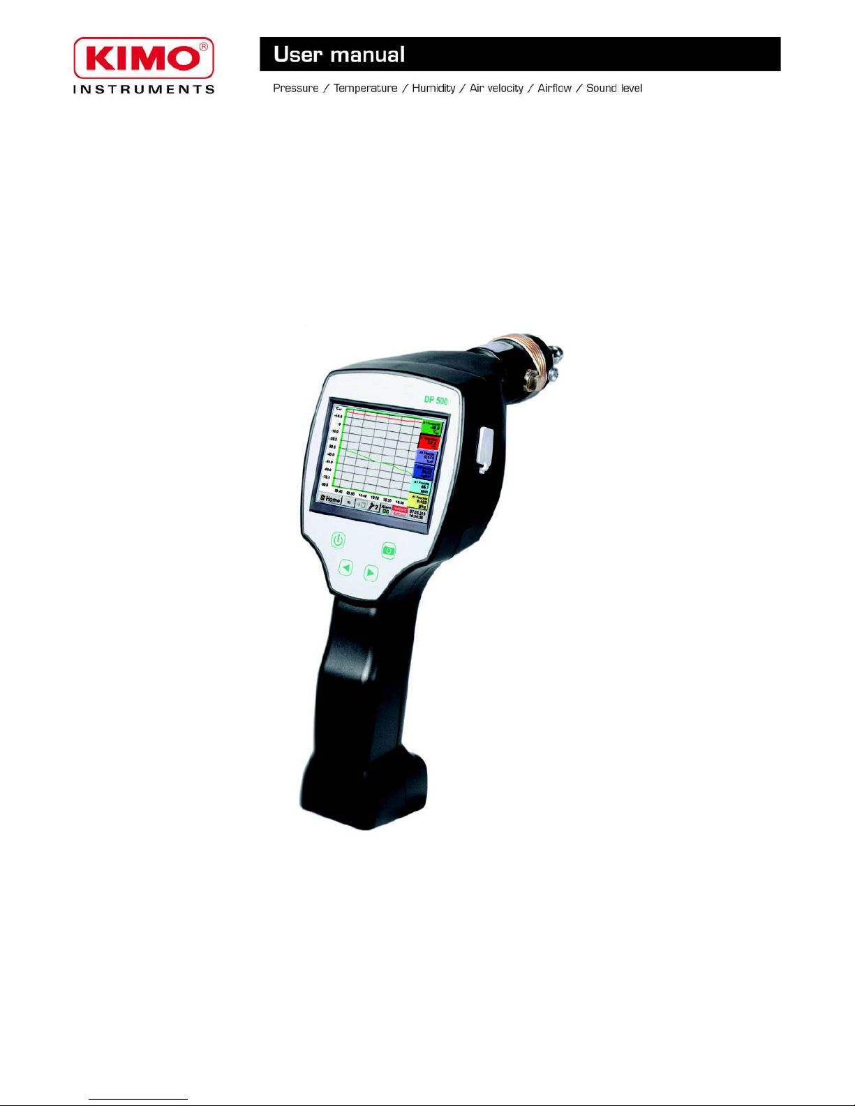
Installation and operating instructions
portable dew point meters
DP500
Page 2

DP500
Foreword
Dear customer,
thank you very much for deciding in favor of the DP 500. Please read this installation
and operation manual carefully before mounting and initiating the device and follow
our advice. A riskless operation and a correct functioning of the DP 500 are only
guaranteed in case of careful observation of the described instructions and notes
2
Page 3

DP500
Table of Contents
1 SAFETY INSTRUCTIONS......................................................................................................................................5
2 APPLICATION AREA..............................................................................................................................................6
3 TECHNICAL DATA..................................................................................................................................................7
4 INSTALLATION AND MEASUREMENTS...............................................................................................................8
4.1 Measurement with measuring chamber, connection via plug nipple....................................................................................8
4.2 Measurement without measuring chamber, connection via external thread G1/2’’...............................................................8
4.3 Dew point measuring at synthetic granules -dries................................................................................................................ 9
5 MAINTENANCE......................................................................................................................................................9
6 CALIBRATION/ ADJUSTMENT..............................................................................................................................9
7 CABLE CROSS SECTION.....................................................................................................................................9
7.1 Sensor circuit points/Output signal:...................................................................................................................................... 9
8 DP 500 OPERATION............................................................................................................................................10
8.1 Keypad............................................................................................................................................................................... 10
8.1.1 On andOff button........................................................................................................................................................ 10
8.1.2 Brightness buttons...................................................................................................................................................... 10
8.1.3 Screenshot-Button...................................................................................................................................................... 10
8.1.3.1 Storing Screenshot................................................................................................................................................................ 10
8.1.3.2 Export Screenshots................................................................................................................................................................ 11
8.2 Touchpanel......................................................................................................................................................................... 12
8.3 Main menu (Home)............................................................................................................................................................ 13
8.3.1 Initialization................................................................................................................................................................. 13
8.3.2 Main menu.................................................................................................................................................................. 14
8.3.2.1 Settings.................................................................................................................................................................................. 15
8.3.2.1.1 Password-Settings......................................................................................................................................................... 15
8.3.2.1.2 Sensor-settings.............................................................................................................................................................. 16
8.3.2.1.2.1 Settings internal Dewpoint-Sensor.......................................................................................................................... 17
8.3.2.1.2.1.1 Definition of the System pressure (relative pressure value)............................................................................. 17
8.3.2.1.2.1.2 Definition of Reference pressure (absolute pressure value)............................................................................ 18
8.3.2.1.2.2 Choice of the sensor type....................................................................................................................................... 18
8.3.2.1.2.3 Name the measurement data and define the decimal places.................................................................................. 20
8.3.2.1.2.4 Recording measurementdata.................................................................................................................................. 21
8.3.2.1.2.5 Alarm-Settings ( Alarm Popup)................................................................................................................................ 21
8.3.2.1.2.6 More Settings (scale analogue output)................................................................................................................... 22
8.3.2.1.2.7 Dew Point Sensor of type CS-Digital...................................................................................................................... 24
8.3.2.1.2.8 Label and setting the description fields................................................................................................................... 24
8.3.2.1.2.9 Type 0 - 1/10/30 Volt and 0/4 – 20 mA.................................................................................................................... 27
8.3.2.1.2.10 Type PT100x and KTY81...................................................................................................................................... 29
8.3.2.1.2.11 Type Pulse (Pulse ration)...................................................................................................................................... 30
8.3.2.1.2.12 Type„No Sensor“.................................................................................................................................................. 31
8.3.2.1.3 Data logger Settings....................................................................................................................................................... 33
8.3.2.1.4 Device Settings.............................................................................................................................................................. 37
8.3.2.1.4.1 Language............................................................................................................................................................... 37
8.3.2.1.4.2 Date &Time............................................................................................................................................................ 37
8.3.2.1.4.3 SD-Card................................................................................................................................................................. 38
8.3.2.1.4.4 System update....................................................................................................................................................... 38
8.3.2.1.4.4.1 Save System Settings..................................................................................................................................... 39
8.3.2.1.4.4.2 Check for new Software updates (USB).......................................................................................................... 39
8.3.2.1.4.4.3 Restore System Settings................................................................................................................................. 40
8.3.2.1.4.5 Factory Reset......................................................................................................................................................... 41
8.3.2.1.4.6 Calibrate touch-screen............................................................................................................................................ 42
8.3.2.1.5 Set backlight.................................................................................................................................................................. 42
8.3.2.1.6 Cleaning......................................................................................................................................................................... 43
8.3.2.1.7 System-Status................................................................................................................................................................ 43
8.3.2.1.8 About DP 500................................................................................................................................................................. 43
8.3.2.2 Chart...................................................................................................................................................................................... 44
8.3.2.3 Chart / Real time values......................................................................................................................................................... 47
8.3.2.4 Channels............................................................................................................................................................................... 49
8.3.2.4.1 Min/Max Function........................................................................................................................................................... 49
8.3.2.5 Real time values.................................................................................................................................................................... 50
3
Page 4

DP500
8.3.2.6 Alarm overview...................................................................................................................................................................... 51
8.3.2.7 Export Data............................................................................................................................................................................ 51
4
Page 5
DP500
1 Safety instructions
Please check whether this manual corresponds with the device type.
Please attend to all notes indicated in this instruction manual. It contains essential information
which has to be followed during installation, operation and maintenance. Therefore this
instruction manual has to be read categorically by the technician as well as by the responsible
user/qualified personnel before installation, initiation and maintenance.
This instruction manual has to be available at any time at the operation site of the DP 500.
Regional and national regulations respectively, have to be observed in addition to this
instruction manual if necessary.
In case of any obscurities or questions with regard to this manual or the instrument please
contact Kimo.
Warning!
Supply voltage!
Contact with supply voltage carrying non-insulated parts may cause an electric shock
with injury and death.
Measures:
• Note all applicable regulations for electrical installations (e. g. VDE 0100)!
• Carry out maintenance only in strain less state!
• All electric works are only allowed to be carried out by authorized qualified personnel.
Warning!
Inadmissible operating parameters!
Undercutting and exceeding respectively of limit values may cause danger to persons
and material and may lead to functional and operational disturbances.
Measures:
• Make sure that the DP 500 is only operated within the admissible limit values indicated on the
type label.
• Strict observance of the performance data of the DP 500 in connection with the application.
• Do not exceed the admissible storage and transportation temperature.
Further safety instructions:
• Attention should also be paid to the applicable national regulations and safety instructions during
installation and operation.
• The DP 500 is not allowed to be used in explosive areas.
Additional remarks:
• Do not overheat the instrument!
• In case of mounting by screwing please use spanner flat (SW27)!
• DP 500 is not allowed to be disassembled!
Attention!
Malfunctions at the DP 500 !
Faulty installation and insufficient maintenance may lead to malfunctions of the DP 500 /
DP 510 which may affect the measuring results and which may lead to
misinterpretations.
5
Page 6

DP500
2 Application area
The new instruments DP 500 are the ideal portable service instruments for dew point measurement for
all types of driers down to -80°Ctd dew point
The 3.5” graphic display with touch screen makes the operation very easy..
The graphic indication of colored measuring curves is unique.
Ideal for measurement of the current dew point and for graphic indication of the dew point curve/the
switching behavior of the drier over a longer period of time.
Up to 100 million measured valued can be stored with date and measuring site name. The measured
data can be transferred to the computer via USB stick or USB cable.
A part from the internal dew point measurement one further optional sensor can be connected like for
example:
Pressure sensors
Flow sensors, VA 400/420
Temperature sensors Pt 100, 4..20 mA
Further dew point sensors
Effective power meters
Optional third-party sensors with the following signals:
0...1/10 V, 0/4...20 mA, Pt100, Pt1000, pulse
Application ranges:
Compressed air: Examination of refrigeration,
membrane, adsorption driers
Technical gases: Residual moisture measurement
in gases like N2, O2 and so on
Plastics industry: Examination of
granulate driers
Medical compressed air/breathing air
6
Page 7
DP500
3 Technical data
Colour screen 3.5“-Touch panel TFT transmissive, graphics, curves, statistics
Interfaces USB
Measuringranges -80…+50 °Ctd
-20…+70 °C
0…100 % rF
Accuracy ± 0,5 °Ctd (-10…+50 °Ctd)
typical:. ± 2 °Ctd
Humiditymeasurands
g/m³, mg/m³, ppm V/V, g/kg, °Ctdatm, % rF
Response Time T95 -50°Ctd ---- -10°Ctd < 10 sec
-10°Ctd ---- -50°Ctd < 5 Minutes
Pressure range Mounting without measuring chamber: -1…50 bar Standard
Mounting with measuring chamber: : -1…16 bar
High pressure version up to 350 bar
Currents upply
Internal rechargeable Li-Ion batteries charging time approx. 4 h
DP 500 operation:approx. 12h,
Power supply unit
100 – 240 VAC/50 – 60 Hz, 12VDC – 1A
Safety class 2, only for application in dry rooms
Dimensions 125 x 96 x 245 mm
Material PlasticPC/ABS
Weight 550 g
Operating temperature
-20...70°C measuring gas temperature
0... 50°C ambient temperature
Storage temperature -20 bis +70°C
Optional
Data Logger, Memory size 2 GB SD memory card standard, optionally
up to 4 GB
EMC DIN EN 61326
7
Page 8
DP500
4 Installation and measurements
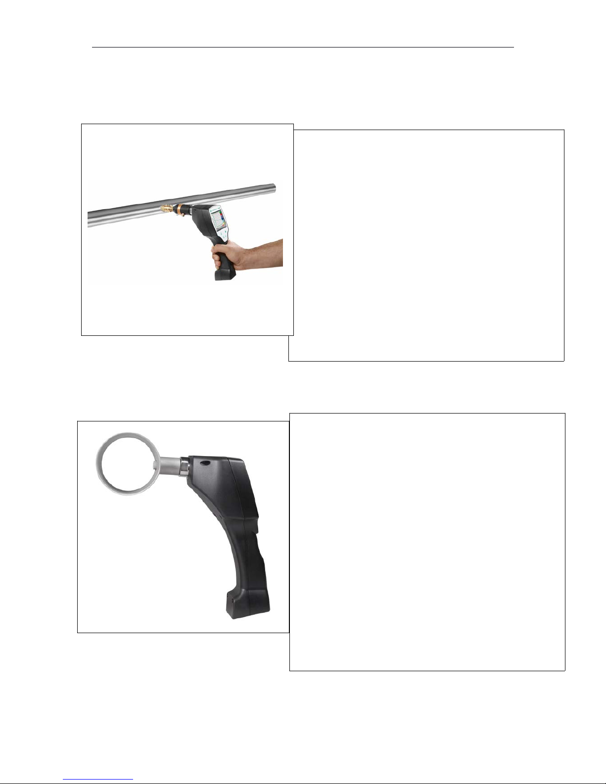
We recommend the use of a measuring chamber!
4.1 Measurement with measuring chamber, connection via plug nipple
4.2 Measurement without measuring chamber, connection via external thread G1/2’’
8
1. Preparation of the measuring point
Let compressed air flow off at the sampling point before
measurement in order to remove condensate and particles.
This avoids a soiling of DP 500 and the measuring chamber.
Stagnant air leads to long adjustment times.
If condensate occurs at the measuring point please check the
compressed-air conditioning before measurement.
2. Switch on DP 500 and wait until the initialization has been
finished.
Please observe the chapter "Operation".
3. Connect the measuring chamber screwed onto DP 500 with
the plug nipple coupling of the measuring point
4. Wait until the value in the display of DP 500 has stabilized.
Depending on the position of the measuring point this may take
up to 15 minutes.
5. Disconnect the measuring chamber from the plug nipple
coupling of the measuring point after measurement. Switch off
DP 500 if you do not want to carry out further measurements.
1. Preparation of the measuring point
Make sure that the measuring point is depressurized.
Please check the sampling point before measurement.
If condensate occurs at the measuring point you should check
the compressed-air conditioning before measurement.
2. Screw the DP 500 (without mounted measuring chamber)
into the measuring point (with internal thread G1/2“). For
mounting you should use the spanner flat (SW27)!
3. Switch on DP 500 and wait until the initialization has been
finished.
Please observe the chapter "Operation".
4. Charge the measuring point slowly with pressure.
5. Wait until the value in the display of DP 500 / DP 510has
stabilized. Depending on the position of the measuring point
this may take up to 15 minutes.
6. After measurement please drain the pressure slowly from the
measuring point.
7. Remove DP 500 from the measuring point. For demounting
the instrument you should use the spanner flat (SW 27)!
8. If you do not want to carry out further measurements please
switch off DP 500.
Page 9
DP500
4.3 Dew point measuring at synthetic granules - dries
5 Maintenance
Cleaning of thesensor
The sensor can be cleaned by careful swinging in distilled water or isopropanol.
Remark:
Do not touch the surface of the sensor pad.
Avoid mechanical impact to the sensor (e. g. by means of a sponge or a brush).
If the sensor is very polluted the only possibility will be an examination and maintenance by the
manufacturer.
6 Calibration/ Adjustment
We recommend an annual calibration and if necessary adjustment of the measuring instrument at the
manufacturer.
Please observe the enclosed inspection certificate.
7 Cable cross section
7.1 Sensor circuit points/Output signal:
AWG16 – AWG28, cable cross-sections: 0,14 - 1,5 mm2
9
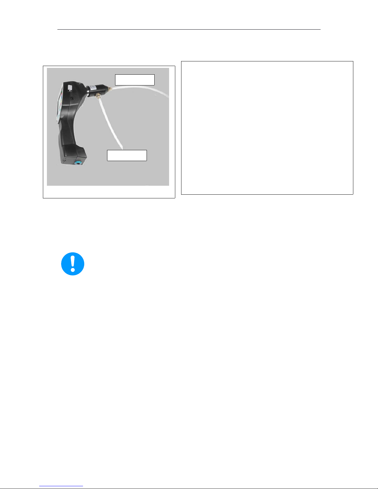
Synthetic granules-dries usually work with a slight positive
pressure in the millibar range. Usein this application,witha slight
excess pressure, the measuring chamber forsynthetic granules
dryer.
Since the air temperature in the synthetic granules dryer is also
very high, the air supply from the synthetic granules dryer to the
measuring chamber via a correspondingly long PFA tube
(recommended length of 1-2 m), which serves as a cooling
section. Note that the measured air temperature in the DP 500
if possible remains below 40 ° C, otherwise please use a longer
PFA tube as a cooling section.
The supply of airinto the measuring chamberviaport A (air
input). On the air output, a PFA tube isconnectedwith a length
ofat least 80 cm. Thisprevents theback flow ofhumidambient
airbackinto the measuring chamber.
Air input
Air output
Page 10
DP500
8 DP 500 operation
The operation of the DP 500 by means of a keypad and a touch panel
8.1 Keypad
8.1.1 On andOff button
On-or Off switching by long press buttons.
8.1.2 Brightness buttons
With the button and the display brightness can be changed.
8.1.3 Screenshot-Button
By pressing the Screenshot-button the actual display content will be stored.
Storage is possible either to a USB Stick or on to the internal SD-card
8.1.3.1 Storing Screenshot
10
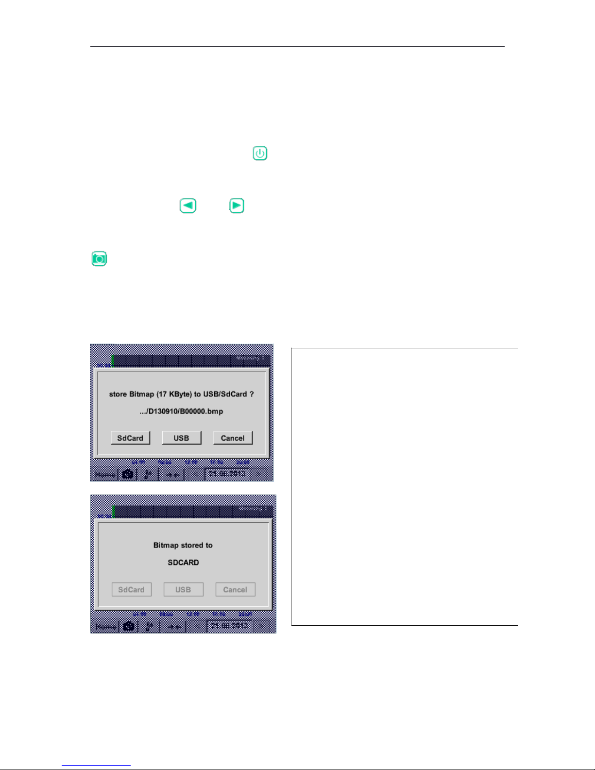
After pressing the Screenshot button a menu (see
left) appears where the storage target, USB Stick or
internal SD-card, could be selected.
The screens are stored as bitmap and the naming is
a consecutively number. For new every day a new
folder is created.
Folder definition : DJJMMTT
D=fix(for date)
JJ = year
MM= month
TT= day
Path: DEV0003/DP500/Bitmap
Example: first picture 10. September 2013
\\DEV0003/P500/Bitmap/D130910/B00000.bmp
Page 11
DP500
8.1.3.2 Export Screenshots
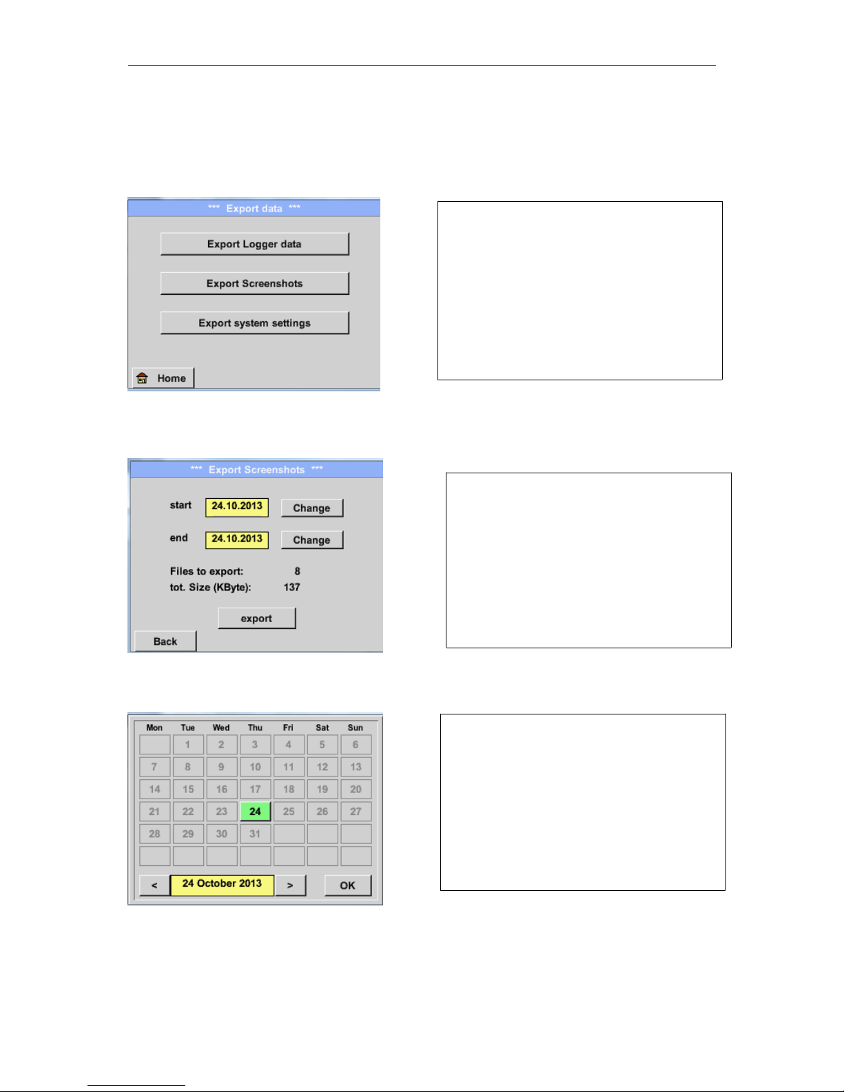
The stored bitmaps on the SD-card could be exported to a USB –Stick.
Main menu Export Data
Main menu Export Data Export Screenshots
Main menu Export Data Export ScreenshotsChange
11
With Export Screenshots the stored
Screenshots will be transferred to a USBStick.
Use the Change buttons to adjust a period
between start and end. Stored bitmaps data in
this period are exported.
The selected date is always green, and the
date numbers of the Sundays are red, like in
the calendar.
On days, where bitmaps were recorded, the
date numbers are optical highlighted.
Page 12
DP500
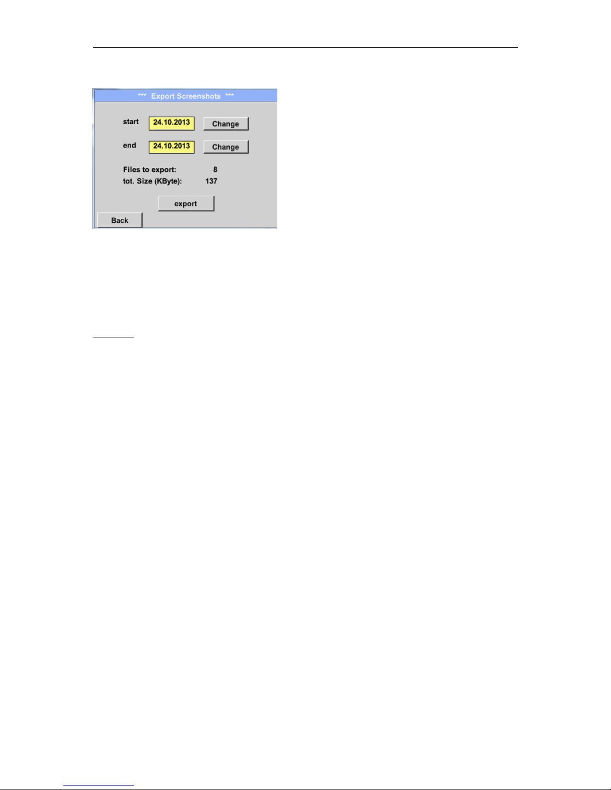
Main menu Export Data Export Screenshots Export
The Screenshots of the selected period are exported to the USB-Stick.
8.2 Touchpanel
The operation is largely self-explanatory and menu-driven via the touch panel.
The selection of the respective menu items occur via short "tapping" with the finger or a soft round
pen.
Attention: Please use no pens or other objects with sharp edges!
The foil can be damaged!
After sensors are connected, they also have to be configured.
Inputs or changes can be made with all white deposit fields.
The measured values can be represented as a curve or values.
Words in green font refer mainly to the pictures in the section of the chapter, but also on important
menu paths or menu items that are related to are in green font.
The menu navigation is generally in a green font!
The table of contents and chapter references in blue font contain links to the respective chapter title.
12
Page 13
DP500
8.3 Main menu (Home)
From the main menu, you can reach every available item.
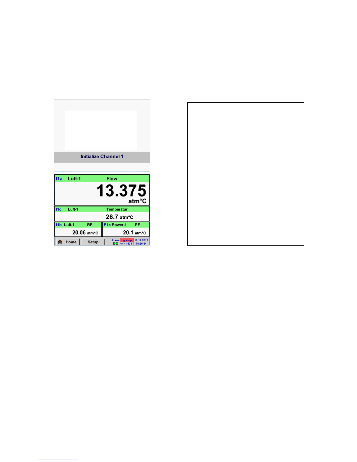
8.3.1 Initialization
Pleas see chapter 10.3.2.1.2 Sensor Settings then select appropriate configurations and set!
13
After switching on the DP500 all channels
are initialized and the menu „ Real time
values „ appears.
DP 500
Page 14
DP500
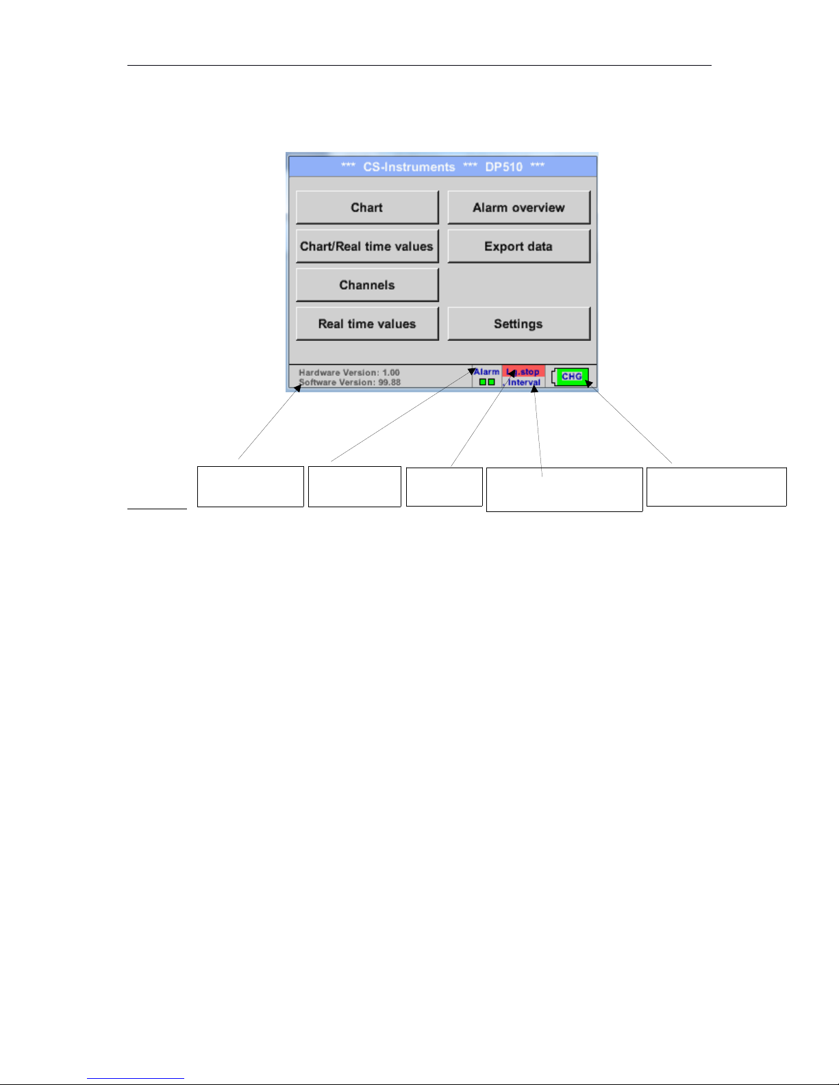
8.3.2 Main menu
Home
Important:
Before the first sensor setting is made, the language and time should be set!
Remark:
Chapter 10.3.2.1.3.1 language
Main Settings Device Settings Set Language)
Chapter 10.3.2.1.3.2 Date & Time
Main Settings Device Settings Date & Time)
14
Hard- and
Software-Version Alarm display
Date & Time
(Battery status every 30s)
Status
Datalogger
Intervall Datalogger and
remaining memory capacity
Page 15
DP500
8.3.2.1 Settings
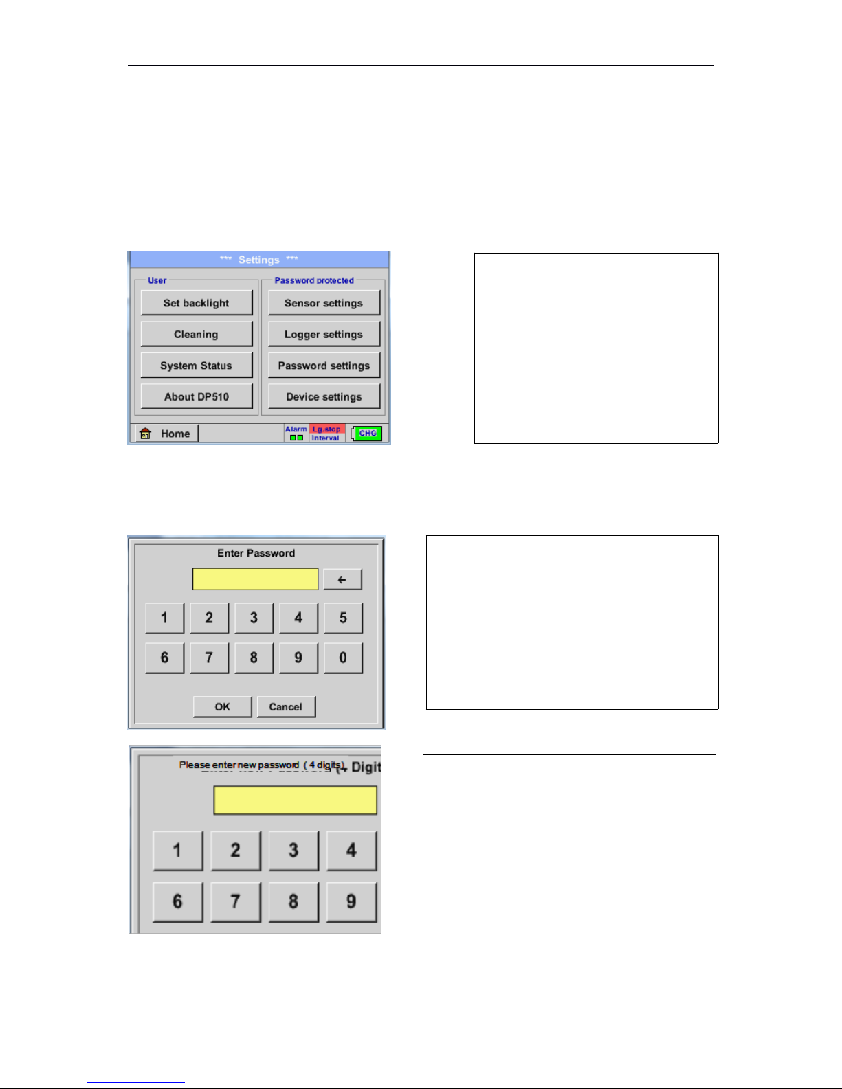
The settings are all protected by a password!
Settings or changes are generally confirmed with OK!
Remark:
If you go back to main menu and then again one of the setting menus is called, you must enter the
password again.
Hauptmenü Settings
8.3.2.1.1 Password-Settings
Main menu Settings Password settings
15
OverviewoftheSettings
Factory settings for password at the time of
delivery: 0000 (4 times zero).
If required, the password can be changed in the
Password settings.
The new password must be entered two times
in a row and in each case confirmed with OK
If an incorrect password is entered there
appears Enter password or New password
repeat in red font.
If you can’t remember the password, please
use Master password in order to enter a new
password.
Remark:
The master password is supplied together with
the instrument’s documentation.
Page 16
DP500
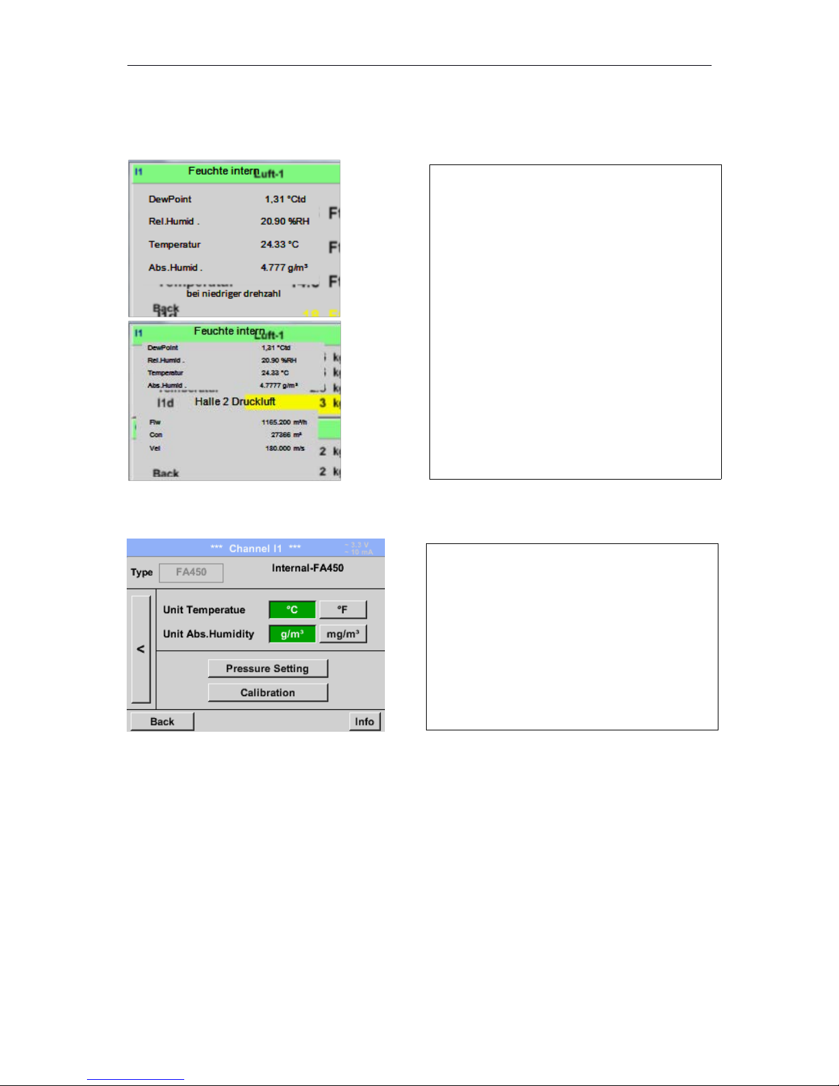
8.3.2.1.2 Sensor-settings
Main menu Settings Sensor settings
Main menu Settings Sensor settings I1 arrow right (2.page)
16
An overview of the available channels appears
after entering the password.
Depending on the version DP 500 without or
with the external sensor channel.
Remark:
Usually there is no preset for the external
channel!
In the upper block it the units for the
temperature, °C and °F, as well as for the
absolute humidity, g/m³ and mg/m³,can be
selected.
Page 17
DP500
8.3.2.1.2.1 Settings internal Dewpoint-Sensor
With the DP 500 the pressure dew point in the pressure line is measured automatically. The pressure
dew point is always related to the pressure in the line.
A pressure input is not necessary, because the measuring principle measures independent of
pressure.
The DP 500 is able simultaneously to the pressure dew point alsocalculate the atmospheric dew point
or dew point at reduced pressure.
For the calculation of the atmospheric dew point (if the gas would be expanded to ambient pressure)
or the dew point at reduced pressure, it is necessary to define the reference pressure and the system
pressure.
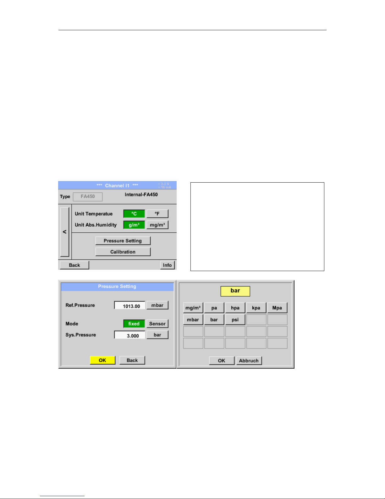
8.3.2.1.2.1.1 Definition of the System pressure (relative pressure value)
Main menu Settings Sensor settings I1 arrow right (2.page)Pressure Setting Fixed
17
By activatingthe button fixed the value of the
system pressure could be inserted in the
corresponding text field.
Pressure unit is freely selectable. Selection
menu is opened by pressing the button
corresponding units
Confirm the settingsby pressing the OK button.
Page 18
DP500
8.3.2.1.2.1.2 Definition of Reference pressure (absolute pressure value)
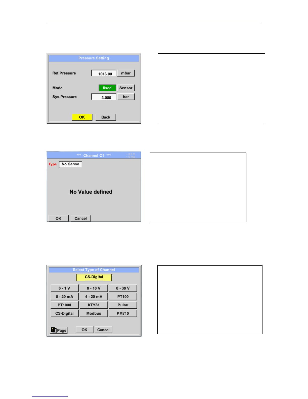
Main menu Settings Sensor settings I1 arrow right (2.page)Pressure Setting
Text field Ref.Pressure
8.3.2.1.2.2 Choice of the sensor type
Main menu Settings Sensor settings C1
Main menu Settings Sensor settings C1Type description field CS-Digital
18
Reference pressure is the pressure for that the
dew point in relaxation will be back calculated.
Default- Value is 1013 mbar (Atm. Pressure).
Confirm the settingsby pressing the OK button.
If still no sensor has been configured, the
Type No Sensor appears.
By pushing the description field Type No
Sensor the list of sensor types appears
(see next step).
Now the Type CS-Digital is selected for the
VA/FA 400 series and confirmed by pressing
the OK button.
Page 19
DP500
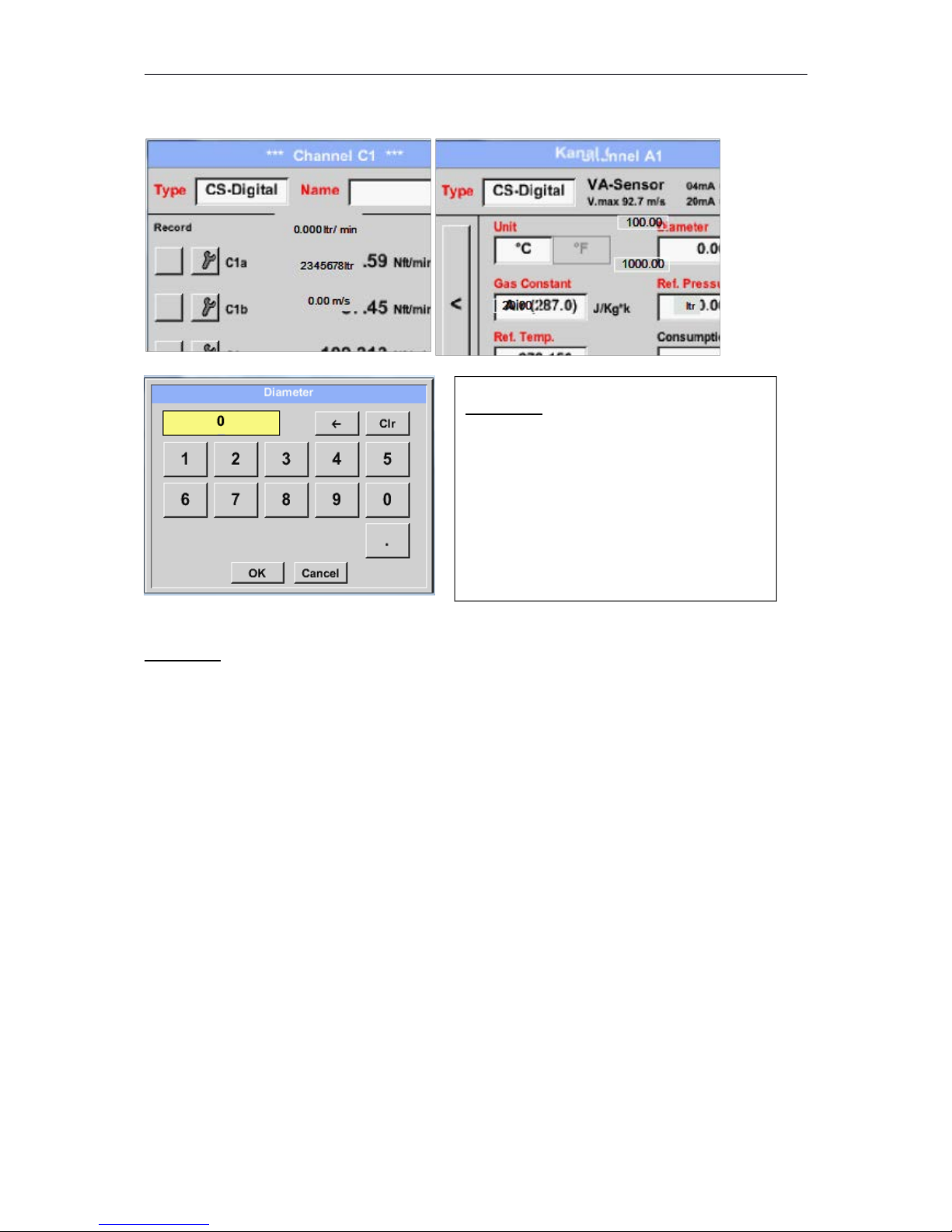
Main menu Settings Sensor settings A1 arrow right (2.page) diameter description field
Important:
The inner diameter should be entered as precisely as possible, because otherwise the
measurement results are not correct!
There is no uniform standard for the tube inner diameter!
(Please, inquire at the manufacturer or measure by your own !)
19
Important:
The inner diameter of flow tube can be
entered here, if this was not automatically
correctly set.
In case of a sensor change the consumption
value of the old sensor could be transferred.
Please confirm by pressing the OK button and
go back with arrow left (1.page).
Page 20
DP500
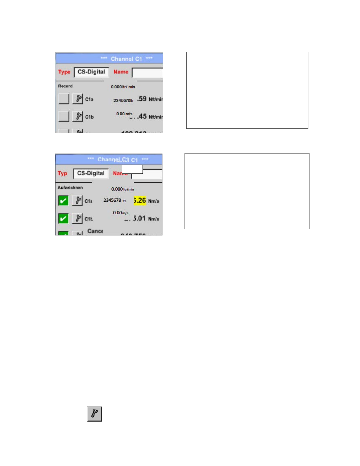
Main menu Settings Sensor settings C1
Main menu Settings Sensor settings C1
More options of sensor settings, see Chapter!
See also chapter10.3.2.1.2.8 label and setting the description fields
Remark:
After confirm with OK, the font is black again and the values and settings are accepted.
Attention:
Reference temperature and reference pressure (factory setting 20 °C, 1000 hPa):
All volume flow values (m³/h) and consumption values indicated in the display are
related to 20 °C, 1000 hPa (according to ISO 1217 intake condition)
0 °C and 1013 hPa (= standard cubic meter) can also be entered as a reference.
Do not enter the operation pressure or the operation temperature under reference
conditions!
8.3.2.1.2.3 Name the measurement data and define the decimal places
Remark:
The Resolution of the decimal places, the Short Name and Value Name are found under the Tool
button!
Tool Button:
20
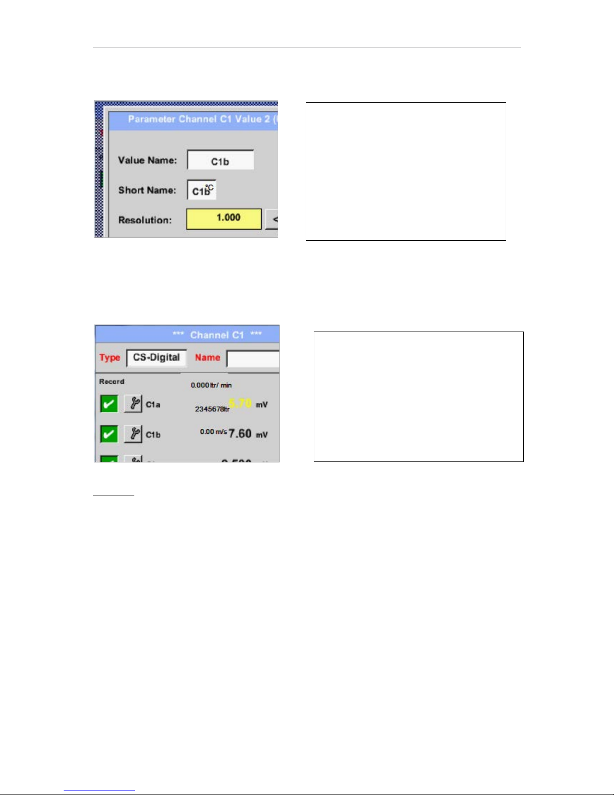
Now you can enter a Name.
After defining the name and confirmation with
OK, the sensor configuration is completed.
Page 21
DP500
Main menu Settings Sensor settings C1 Tool Button
See chapter 10.3.2.1.2.8 label and setting the description fields
8.3.2.1.2.4 Recording measurementdata
Main menu Settings Sensor settings C1 Record Button
Attention:
Before the selected measurement data are recorded, the data logger must be activated after the
settings(See chapter 12.2 Logger-Settings(Datalogger)).
8.3.2.1.2.5 Alarm-Settings ( Alarm Popup)
Main menu Settings Sensor settings C1 Alarm-Button
By pushing an alarm button, the following window appears:
21
For the recorded Value there can be entered
a Name with 10 characters and later in
menu item Graphics/Real time values it is
easier to identify it.
Otherwise the Name is, for example, C1b.
The channel name is C1 and a is the first
measurement data at the channel,
the Second b and the Third c.
The Resolution of the decimal places is
simply adjustable by pushing right and left
(0 to 5 decimal places).
Use the Record buttons to select the
measurement data that will be stored by
activated data logger.
Page 22
DP500
Main menu Settings Sensor settings C1 Alarm-Button Alarm-1- und Alarm-2-buttons +
Popup-buttons
Main menu Settings Sensor settings C1
Remark:
After confirm with OK, the font is black again and the values and settings are accepted
8.3.2.1.2.6 More Settings (scale analogue output)
Main menu Settings Sensor settings A1arrow right (2.page) More settings
22
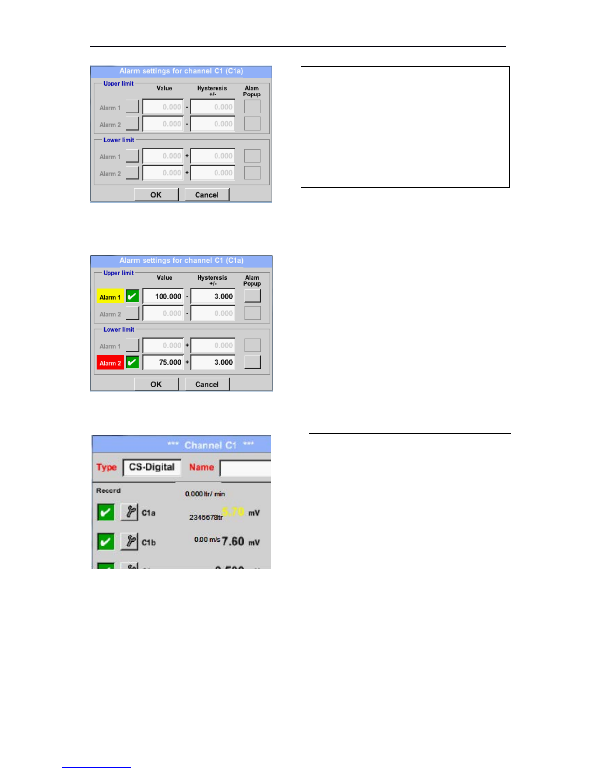
In the alarm settings an Alarm 1and Alarm 2
incl. Hysteresis can be entered for each
channel.
In the menu Alarm overview (can be reached
from the main menu), the alarm settings are
clearly represented.
Here for example the Alarm-1 yellow and the
Alarm-2 red.
After alarm setting for Channel C1a.
Page 23
DP500
The settings are completed after pressing the OK button!
Remark:
After confirming with OK, the font is black again and the values and settings are accepted.
23
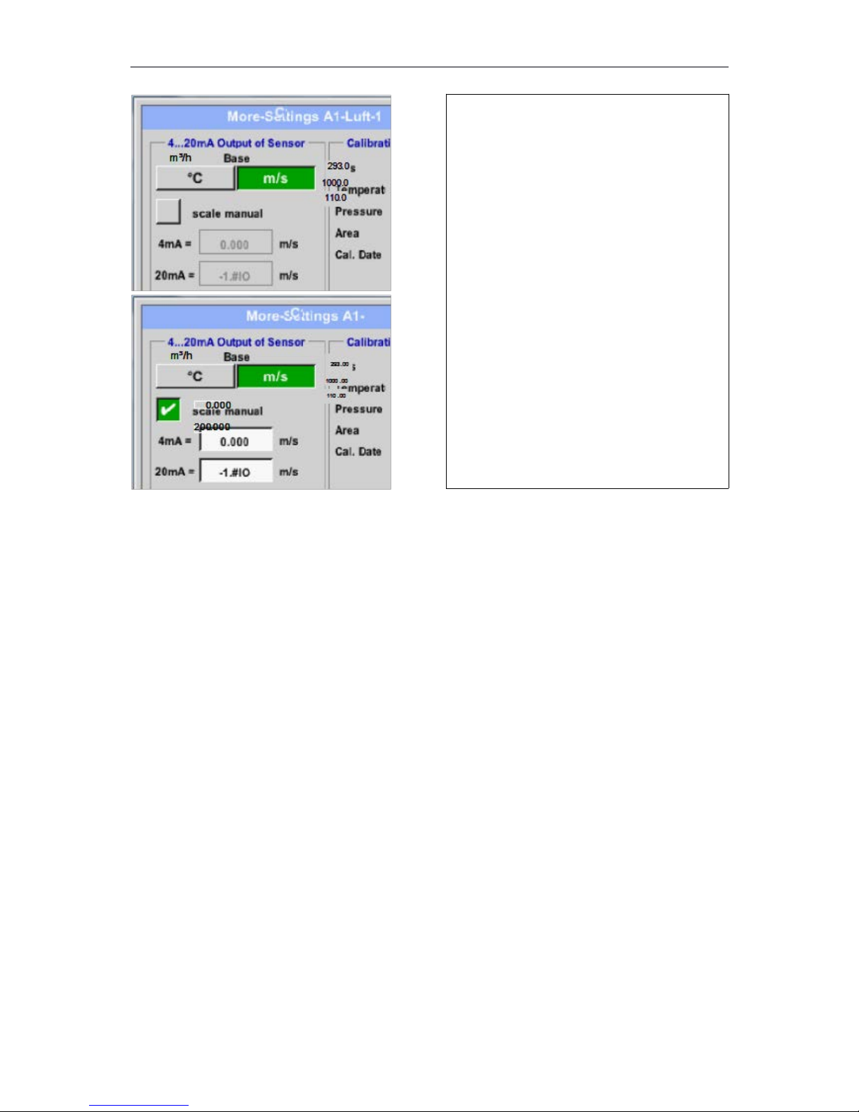
In More-Settings, you can define whether the
4 - 20 mA analogue output of the sensor
based on the flow rate or velocity.
The green highlighted description field is
selected!
In addition, you can push the scale manual
button and set the measuring range.
After confirming with OK, the settings are
assumed.
Remark:
More-Settings only for type CS-Digital
available!
Page 24
DP500
8.3.2.1.2.7 Dew Point Sensor of type CS-Digital
First step: choose an unused sensor channel
Main menu Settings Sensor settings A1
Second step: choose type CS-Digital
Main menu Settings Sensor settings A1 Type description field CS-Digital
Third step: confirm with OK two times
Now, a Name(see Chapter 10.3.2.1.2.8 panel and setting the description fields), the alarm settings (see Chapter
10.3.2.1.2.5 Alarm-Settings) and the recording-settings (see Chapter 10.3.2.1.2.4 Recording measurement
data) and the Resolution of the decimal places (see Chapter 10.3.2.1.2. 3Name measurement data and define
the decimal places) can be determined.
8.3.2.1.2.8 Label and setting the description fields
Main menu Settings Sensor settings C1
The Alarm-(See chapter 10.3.2.1.2.5Alarm-Settings) and Record-Buttons (See chapter 10.3.2.1.2.4
Recording measurement data), the Resolution of the decimal places and the Short name or the
Value-Name (See chapter 10.3.2.1.2.3name measurement data and define decimal places) and the
More-Settings (See chapter 10.3.2.1.2.6 More settings) are all described in Chapter 10.3.2.1.2Sensor-
Settings.
Main menu Settings Sensor settings C1description field Name
24
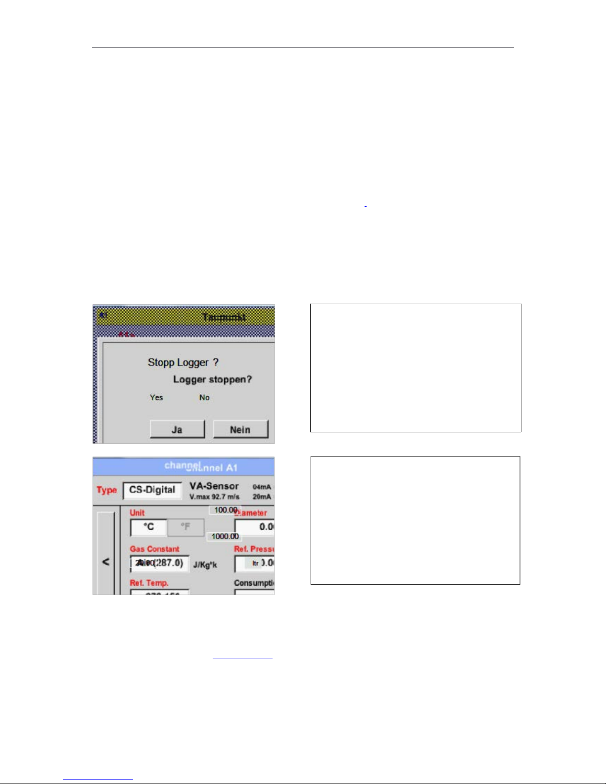
If the data logger is activated, the following
window will appear and via pushing Yes it can
be disabled.
(Only activated, if already settings and recordings are
made)
Remark:
If sensor settings are defined or changed, the
data logger must be stopped.
Changes or entries can be made by
pressing the highlighted white fields
Page 25
DP500
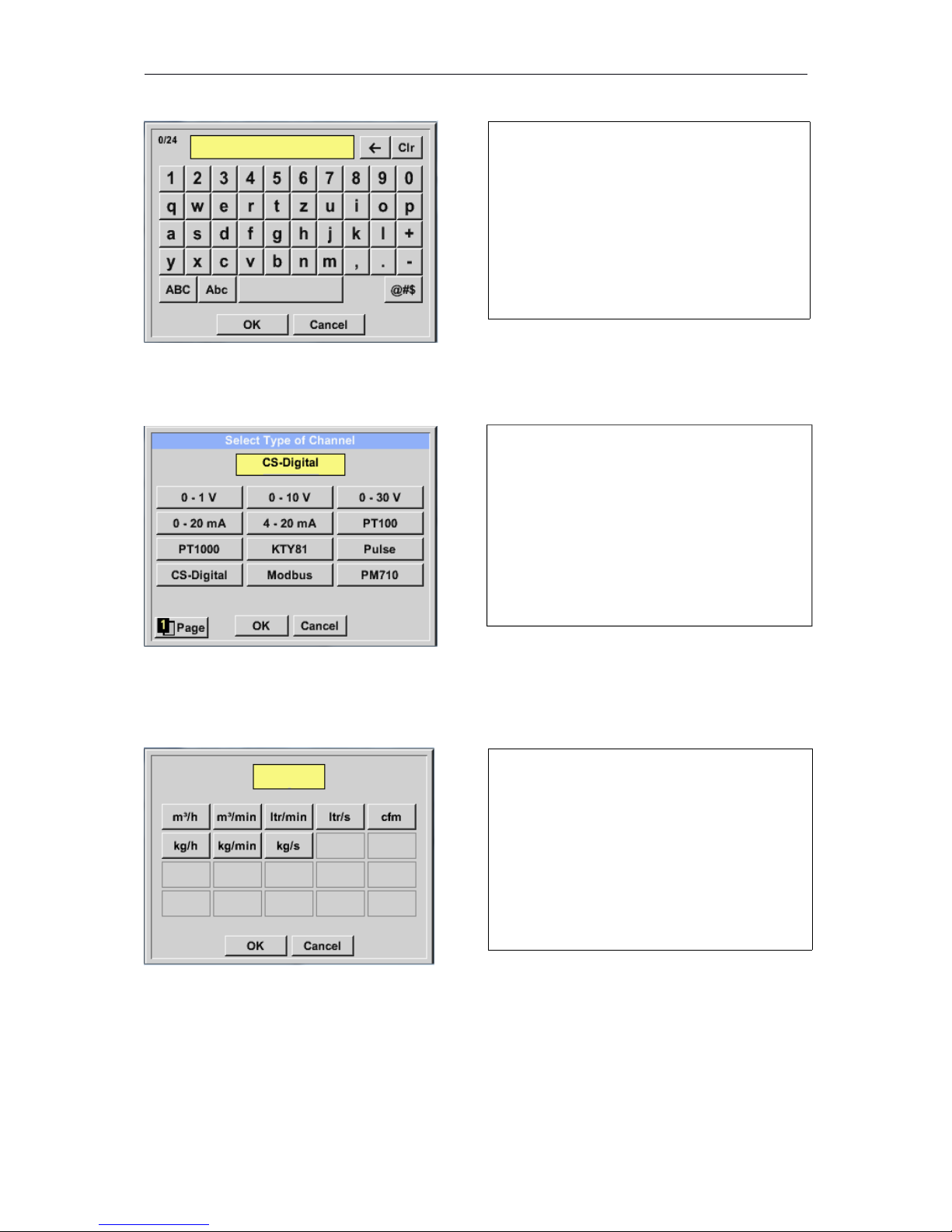
Main menu Settings Sensor settings C1description field Type
See also chapter 10.3.2.1.2.9 Configuration of analogue sensors
Main menu Settings Sensor settings C1description field Unit
Main menu Settings Sensor settings A1 arrow right (2.page) description field of
numerical value
25
It is possible to enter a name with
24 characters.
You can choose the following options, after
pushing the Type description field.
(shown in figure)
A preset selection of suitable Units.
Page 26
DP500
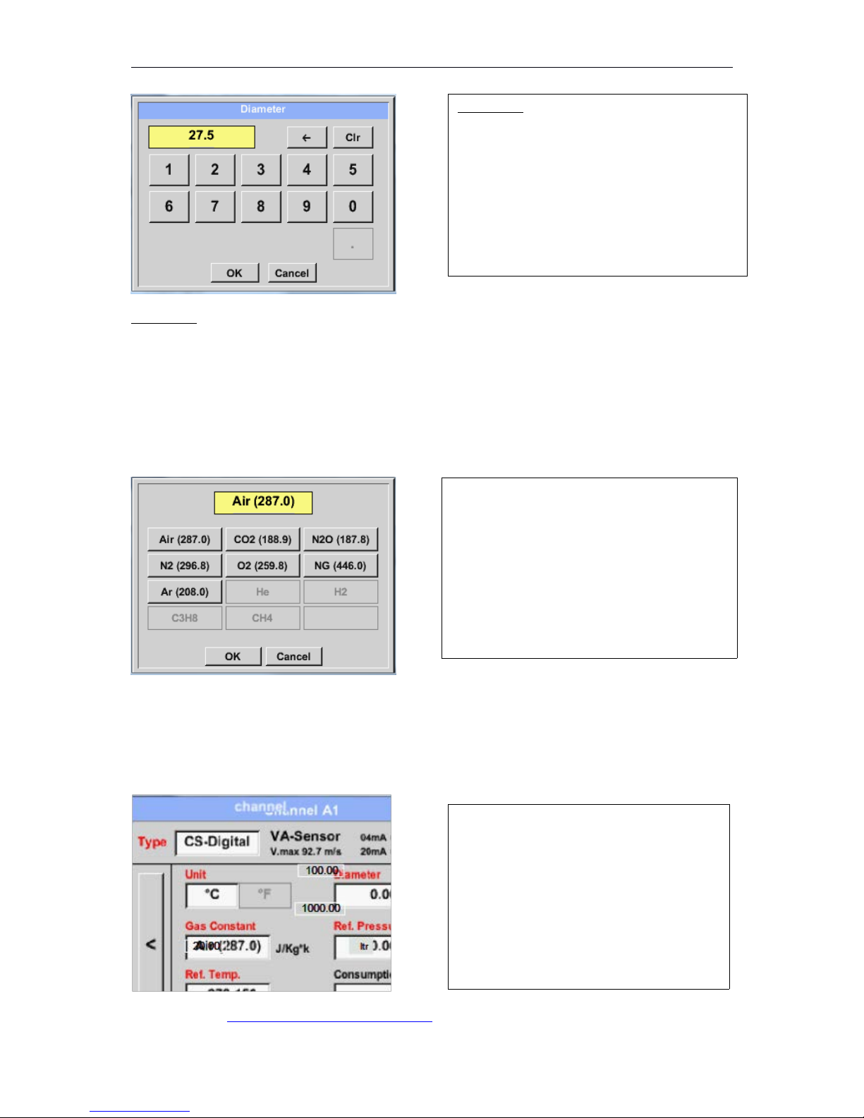
Important:
The inner diameter should be entered as precisely as possible, because otherwise the
measurement results are not correct!
There is no uniform standard for the tube inner diameter!
(Please, inquire at the manufacturer or measure by your own!)
Main menu Settings Sensor settings A1 arrow right (2.page Gas Constant description
field
In the same way as here in chapter 10.3.2.1.2. 8 Label and setting the description fields described,
the remaining description fields can be labelled.
Main menu Settings Sensor settings C1 arrow right (2.page)
See also Chapter 10.3.2.1.2.2 Choice of the sensor type
Remark:
26
Important:
The inner diameter of flow tube can be
entered here, if this was not automatically
correctly set.
Inner diameter is entered here for example
27.5 mm.
A preset selection of suitable Gas Constants.
The red labeled description fields indicate,
that different values, such as the Diameter
and the Type, have been changed or added.
Page 27
DP500
After confirming with OK, the font is black again and the values and settings are accepted.
Attention:
Reference temperature and reference pressure (factory setting 20 °C, 1000 hPa):
All volume flow values (m³/h) and consumption values indicated in the display are
related to 20 °C, 1000 hPa (according to ISO 1217 intake condition)
0 °C and 1013 hPa (= standard cubic meter) can also be entered as a reference.
Do not enter the operation pressure or the operation temperature under reference
conditions!
8.3.2.1.2.9 Type 0 - 1/10/30 Volt and 0/4 – 20 mA
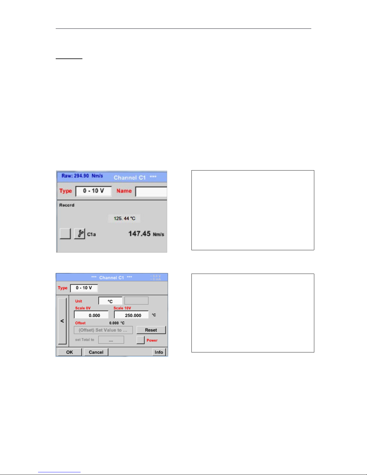
Main menu Settings Sensor settings C1 Type description field 0 - 1/10/30 V
Main menu Settings Sensor settings C1 arrow right (2.page)
27
Please see the scale of the sensor (here for
example Type 0 – 10V corresponds to
0 - 250 ° C) from the data sheet of the
connected sensor.
By Scale 0V enter the lower and by Scale10V
the upper scale value.
By Scale 0Venter the lower and by Scale10V
the upper scale value
The Sensor Supply Voltage is switched On,
if it´s required by the sensor type, otherwise
off (no green hook).
Please confirm by pressing the OK button
Page 28
DP500
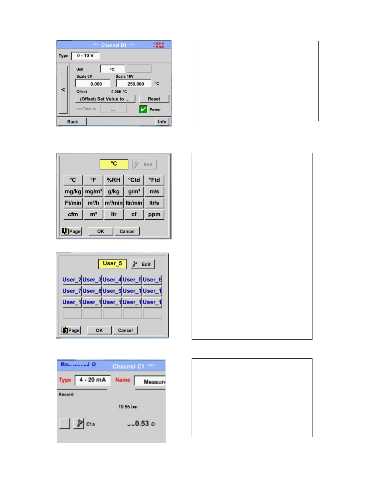
Main menu Settings Sensor settings C1 arrow right (2.page)description field Unit
Main menu Settings Sensor settings C1 Type description field 0/4 - 20 mA
28
It is possible to define a Offset-Value. With
the Set Value to-button (Offset) you enter it.
The positive or negative difference of the
Offset will be displayed.
By pressing the Reset-button the Offset will
be deleted
A preset selection of suitable units by Type0
- 1/10/30 V and 0/4...20 mA.
The different pages could be displayed by
pressing the Page-button.
In addition User specific units could be
defined
Here with the Edit button could analog to
description field a User unit be defined.
Here for example Type 4 - 20 mA.
Page 29
DP500
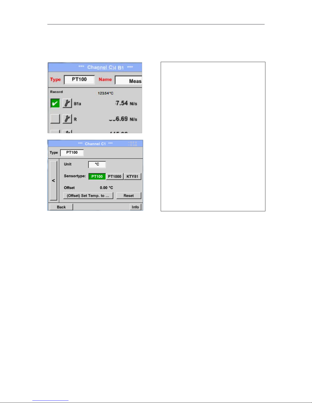
8.3.2.1.2.10 Type PT100x and KTY81
Main menu Settings Sensor settings B1 Type description field PT100x
29
Here the sensor type PT100 and the Unit in
°C are chosen, alternatively the sensor types
PT1000 and KTY81, as well as the Unit °F
can be selected.
More setting options, see chapter
10.3.2.1.2.10 Type 0 - 1/10/30 Volt and 0/4 20 mA!
Page 30
DP500
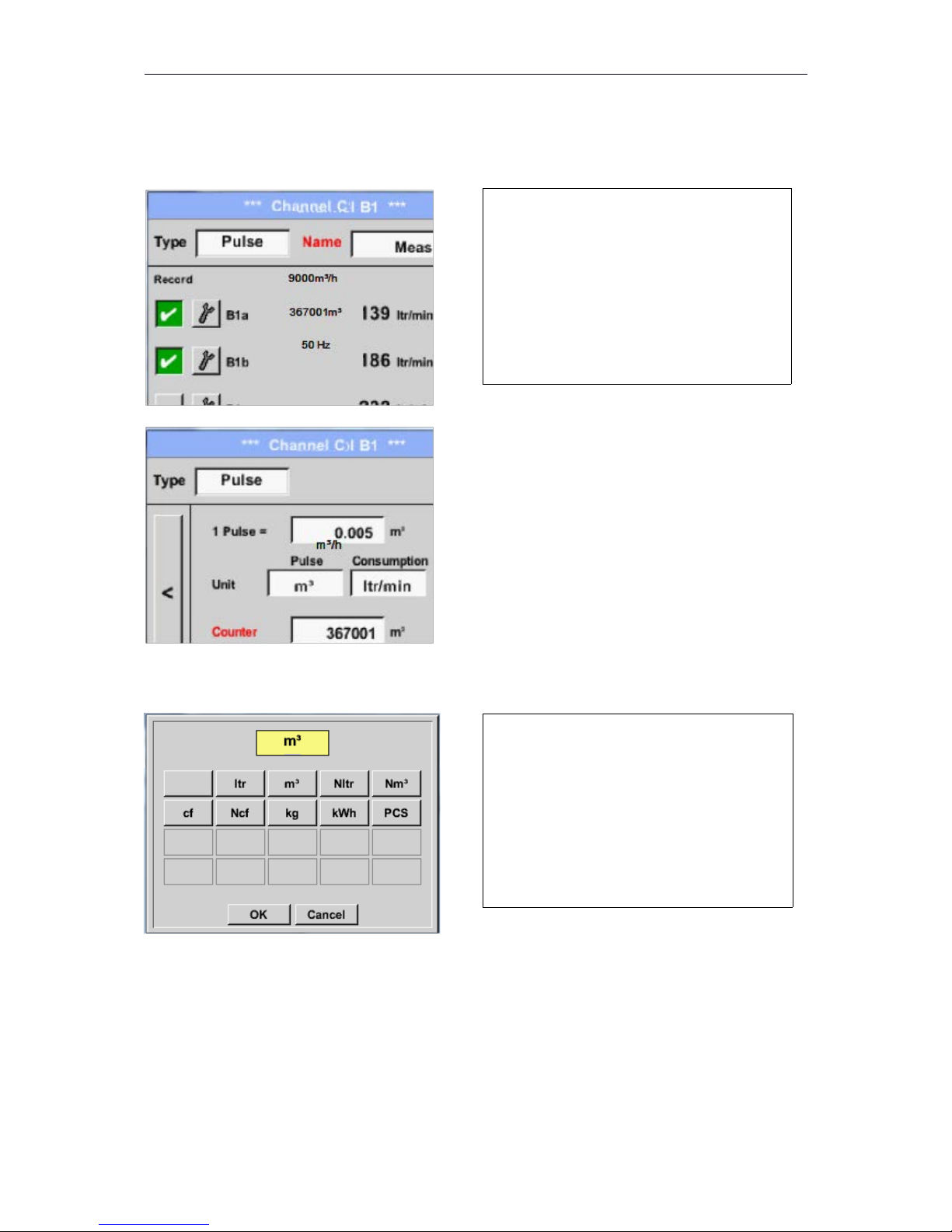
8.3.2.1.2.11 Type Pulse (Pulse ration)
Main menu Settings Sensor settings B1 Type description fieldPulse
Main menu Settings Sensor settings B1 arrow right (2.page) Unit Pulses
30
Typically the value with unit of 1 Pulse is
standing on the sensor and can directly
entered to the 1 Pulse = description field.
Remark:
Here, all description fields are already
labeled or occupied.
By Unit Pulse you can choose between a
flow volume or a power consumption unit.
Page 31
DP500
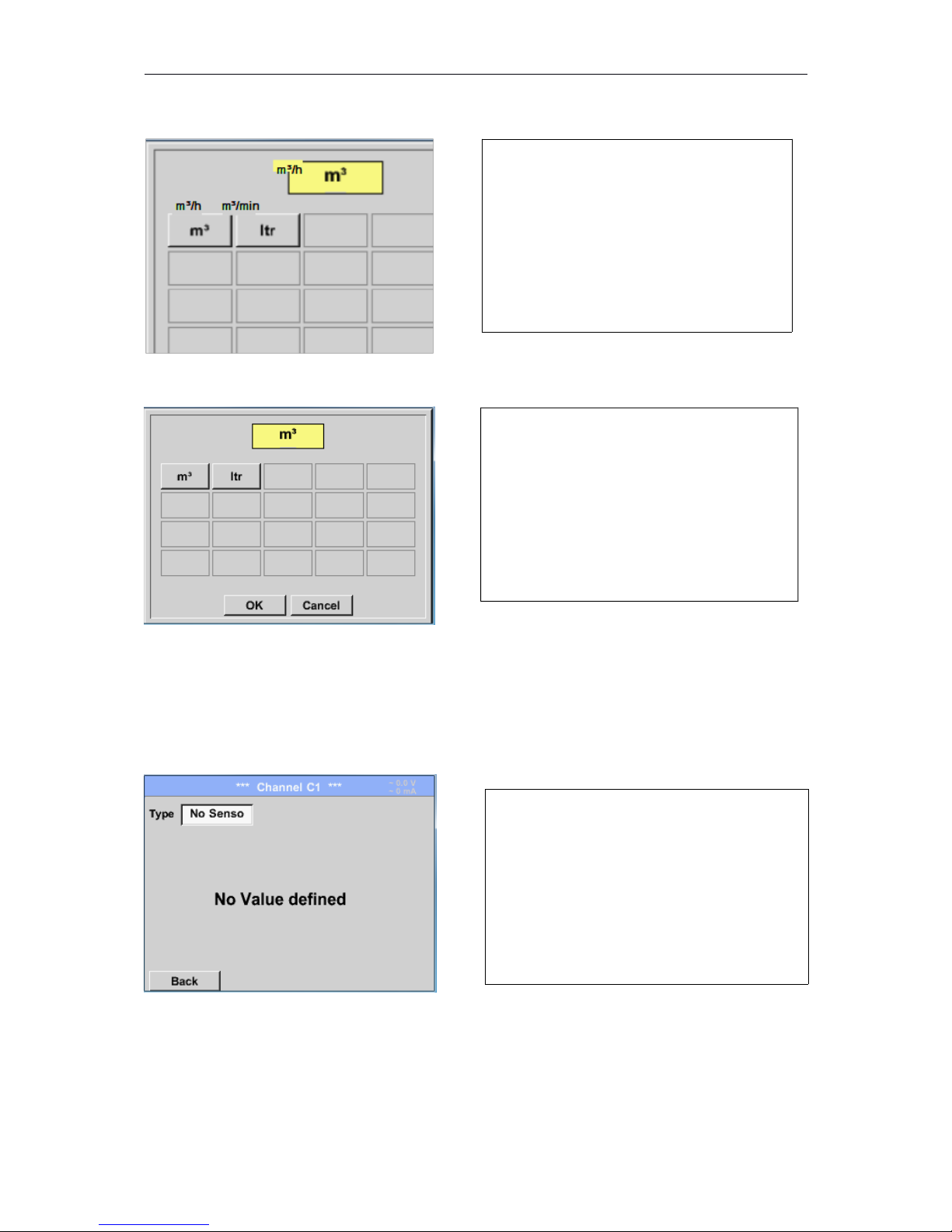
Main menu Settings Sensor settings B1 arrow right (2.page)Unit Consumption
Main menu Settings Sensor settings B1 arrow right (2.page) Unit Counter
More setting options, seechapter10.3.2.1.2.10Type 0 - 1/10/30 Volt and 0/4 - 20 mA!
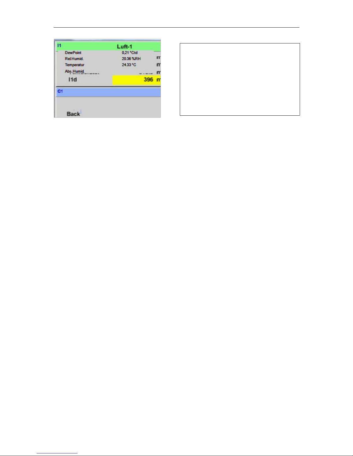
8.3.2.1.2.12 Type„No Sensor“
Main menu Settings Sensor settings C1Type description field No Sensor
31
Unit of current Consumption by Type Pulse
Remark:
Example with the unit cubic meters / hour
The available Units for the Unit of Counter by
Type Pulse
The counter can be set any time to any
value you need.
Is used to declare a not currently needed
channel as No Sensor defined.
Page 32
DP500
32
If you go to Type No Sensor Back, the
channel will appear as unused.
Page 33
DP500
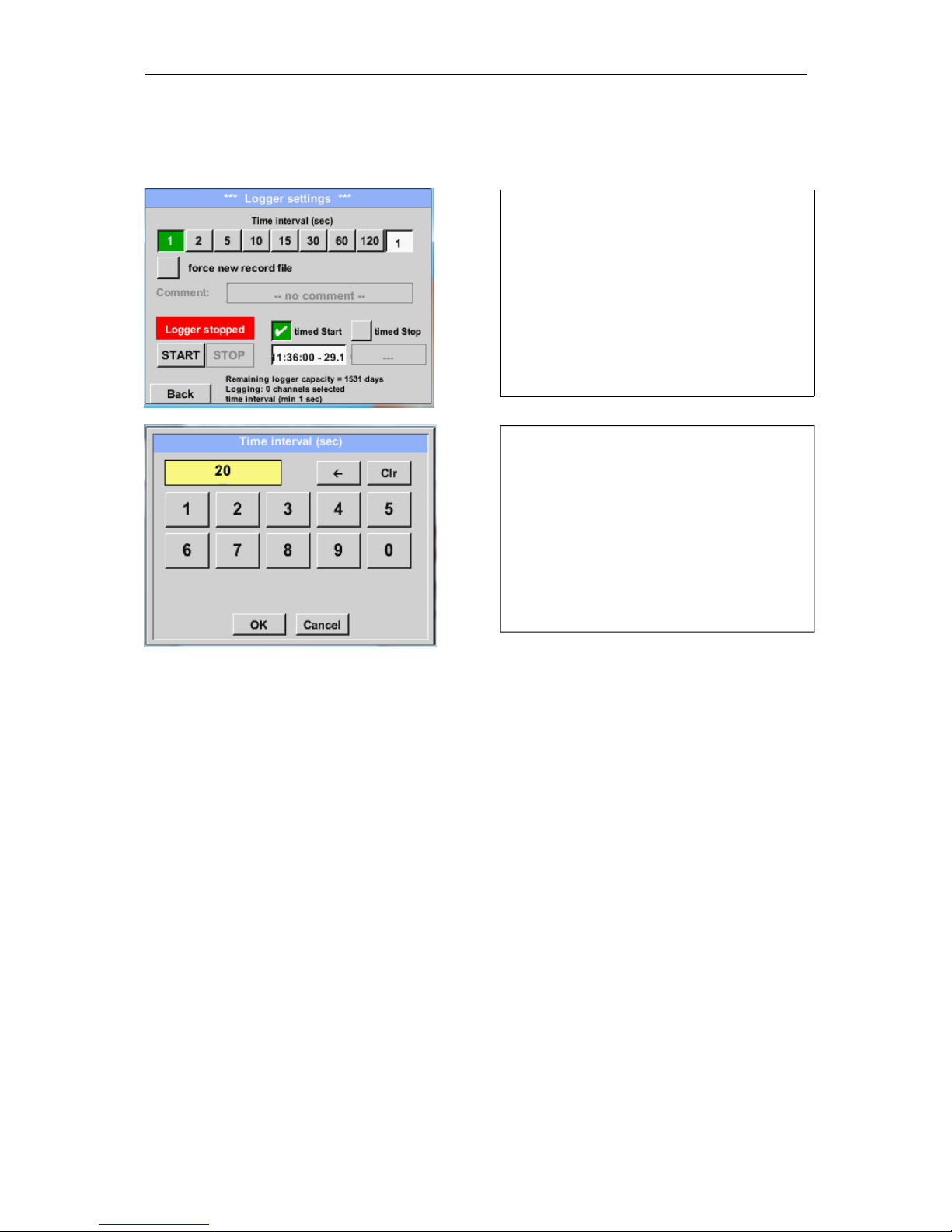
8.3.2.1.3 Data logger Settings
Main menu Settings Logger settings
Remark:
If more than 12 measurement data are recorded at the same time, the smallest possible time
interval of the data logger is 2 seconds.
And if more than 25 measurement data are recorded at the same time, the smallest possible
time interval of the data logger is 5 seconds.
33
In the top row you can select the predefined
Time intervals1, 2, 5, 10, 15, 30, 60 and 120
seconds for recording.
A different, individual Time interval can be
entered in the highlighted white description
field right at the head, where the currently
set Time interval is always displayed.
Remark:
The largest possible Time interval is 300
seconds.
Page 34
DP500
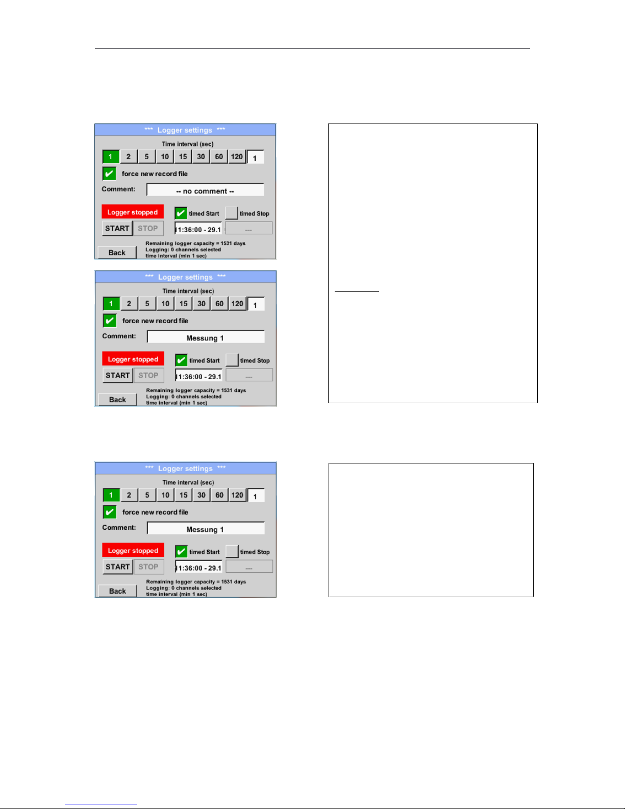
Main menu Settings Logger settings force new Record File button
or
Main menu Settings Logger settings force new Record File button Comment description
field
Main menu Settings Logger settings timed Start button
34
A new recording file will be created by
pushing the force new record file button
and a name or comment can be entered by
the choice of the Comment description field.
Important:
If a new recording file should be created,
the force new record file button must be
activated.
Otherwise, the last applied recording file
is used.
By pushing the timed Start button and then
the date/time description field below, the
date and the start time can be set for a data
logger recording.
Remark:
If the start time is activated, it will
automatically be set at the current time plus
a minute.
Page 35
DP500
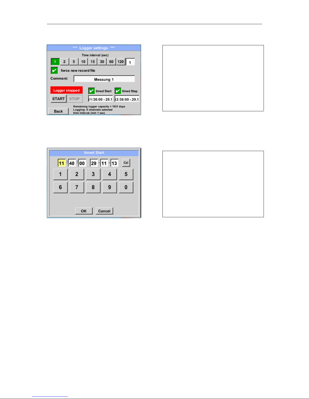
Main menu Settings Logger settings timed Stop button
Main menu Settings Logger settings timed Start button/timed Stop button
Date/Time description field
35
By pushing the timed Stop button and then
the date/time description field below, the
date and the stop time can be set for a data
logger recording.
Remark:
If the stop time activated, it will automatically
be set to the current time plus an hour.
After pushing the date/time description field
a window will appear where the yellow
marked area of the time or date can always
be set and changed.
Page 36
DP500
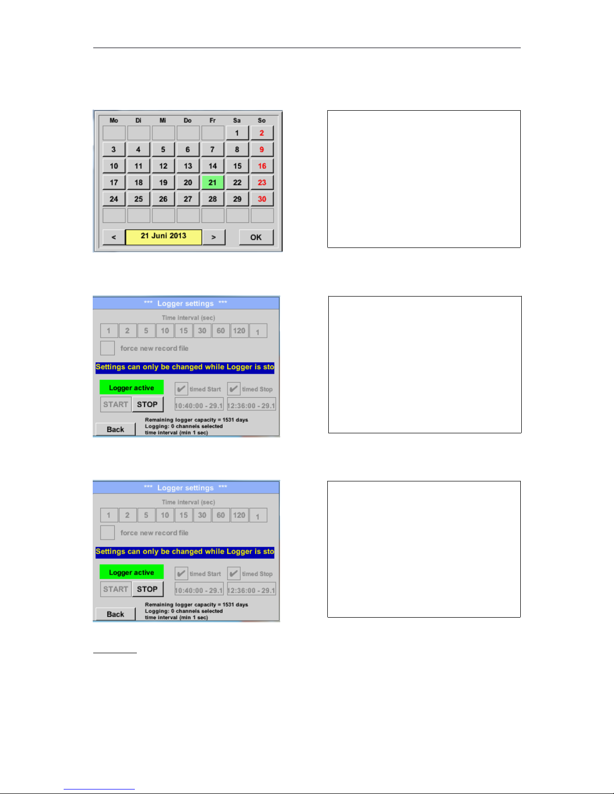
Main menu Settings Logger settings timed Start button/timed Stop button
Date/Time description field Cal button
Main menu Settings Logger settings Start button
Main menu Settings Logger settings Start button/Stop button
Important:
If a new recording file should be created, the force new record file button must be activated.
Otherwise, the last applied recording file is used.
36
With the Cal button the desired date can
be easily select from the calendar.
After the start and stop time activation and
the created settings, the Start button will
be pushed and the data logger is armed.
The data logger starts the recording at the
set time!
The data logger can be started without
activated time settings, use the Start and
Stop buttons for activate and disable.
Left below there will be shown how many
values are recorded and how long there
still can be recorded.
Remark:
The settings cannot be changed, if the
data logger runs.
Page 37
DP500
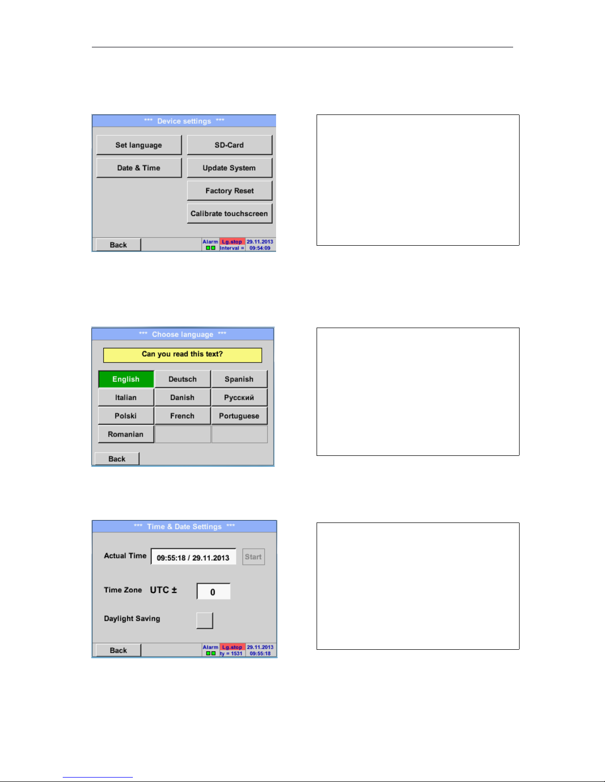
8.3.2.1.4 Device Settings
Main menu Settings Device settings
8.3.2.1.4.1 Language
Main menu Settings Device settings Set language
8.3.2.1.4.2 Date &Time
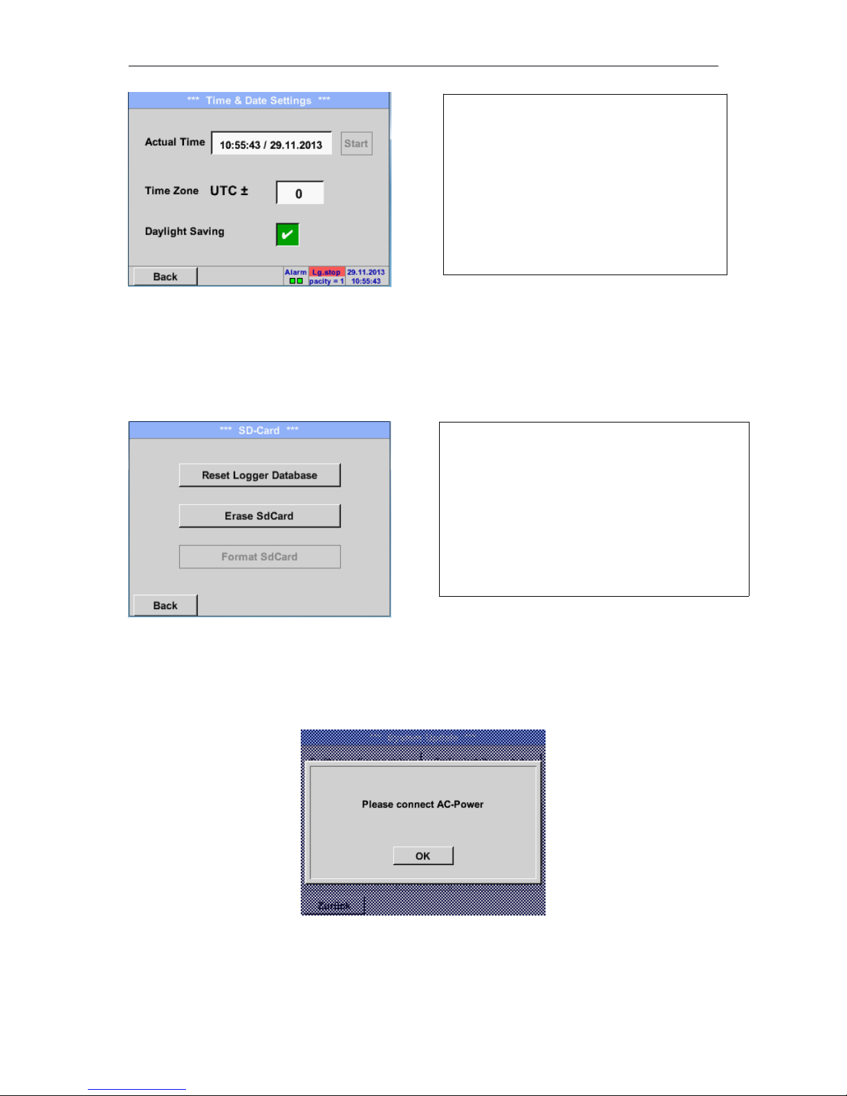
Main menu Settings Device settings Date & Time
37
Overview of Device settings
Here you can select one of 10 languages for
the 500.
By pushing the Time Zone description field
and enter the correct UTC, you can set the
correct time all over the world.
Page 38
DP500
8.3.2.1.4.3 SD-Card
Main menu Settings Device settings SD-Card Reset Logger Database
Main menu Settings Device settings SD-Card Erase SdCard
8.3.2.1.4.4 System update
Important!
System update can only be done with power supply connected to ensure there is a continuous
power supply during the update.
38
The summer and winter time switchover is
realized by pushing the Daylight Saving
button.
By pressing Reset Logger Database all actual
stored data on SD-Card will be blocked for use in
DS 400. Nevertheless all data are still stored and
available for external use only.
By pressing EraseSdCard all Data on the SDCard will be deleted.
Page 39
DP500
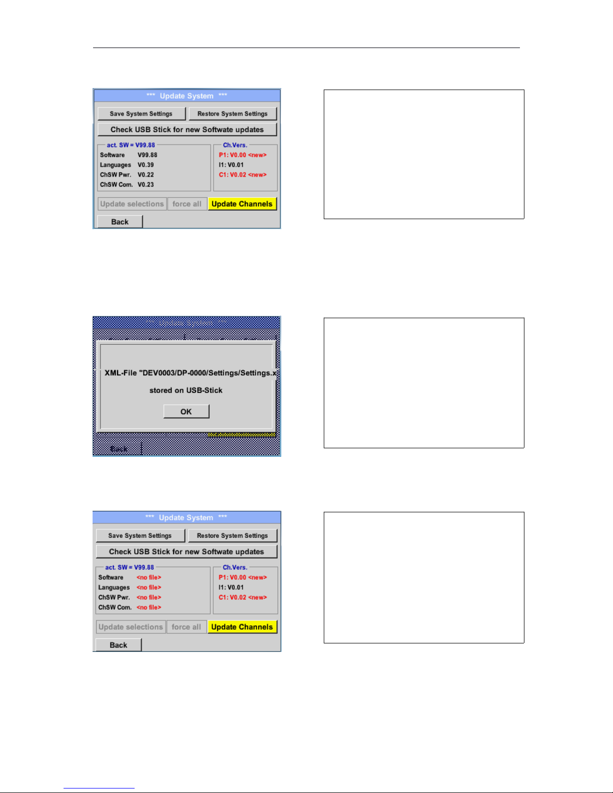
Main menu Settings Device settings System-Update
8.3.2.1.4.4.1 Save System Settings
Main menu Settings Device settings System-Update Save System Settings
8.3.2.1.4.4.2 Check for new Software updates (USB)
Main menu Settings Device settings Update System Check USB Stick for new Software
updates
39
Overview of the Update System features
Stores the channel and system settings in
XML format on a USB stick.
If after pushing the Check USB Stick for new
Software updates button the following
messages in the window appears, then
DP 500 DP 510 is not connected properly
with the USB stick or no files are available.
Page 40
DP500
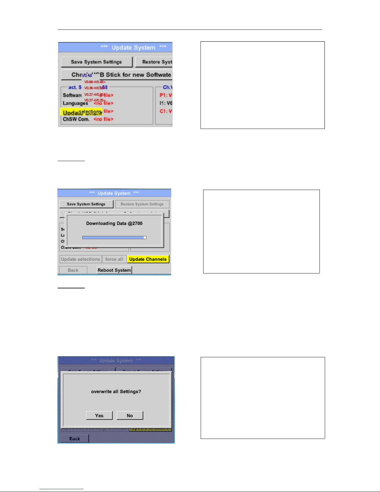
Main menu Settings Device settings System UpdateUpdate selections
Important:
If the Reboot system button after the update appears, he must be pushed to restart the DP 500!
Main menu Settings Device settings System UpdateUpdate channels
Important:
If after the channel update the Reboot system button appears, it has to be pushed to restart the
DP 500.
Update of the channels maybe requires a repeating this procedures with a reboot of the
system. In that case after reboot of the system a popup is displayed.
8.3.2.1.4.4.3 Restore System Settings
Main menu Settings Device settings Update System Restore System Settings
40
Update for the available channels of the
DP 500
With the help of the Restore System
Settings button the channel and system
settings can be reset to the last saved
version.
If the DP 500 is correctly connected to USB,
and new version available it will displayed.
Right aside it shows the current (old) and
another (new) available versions
Page 41
DP500
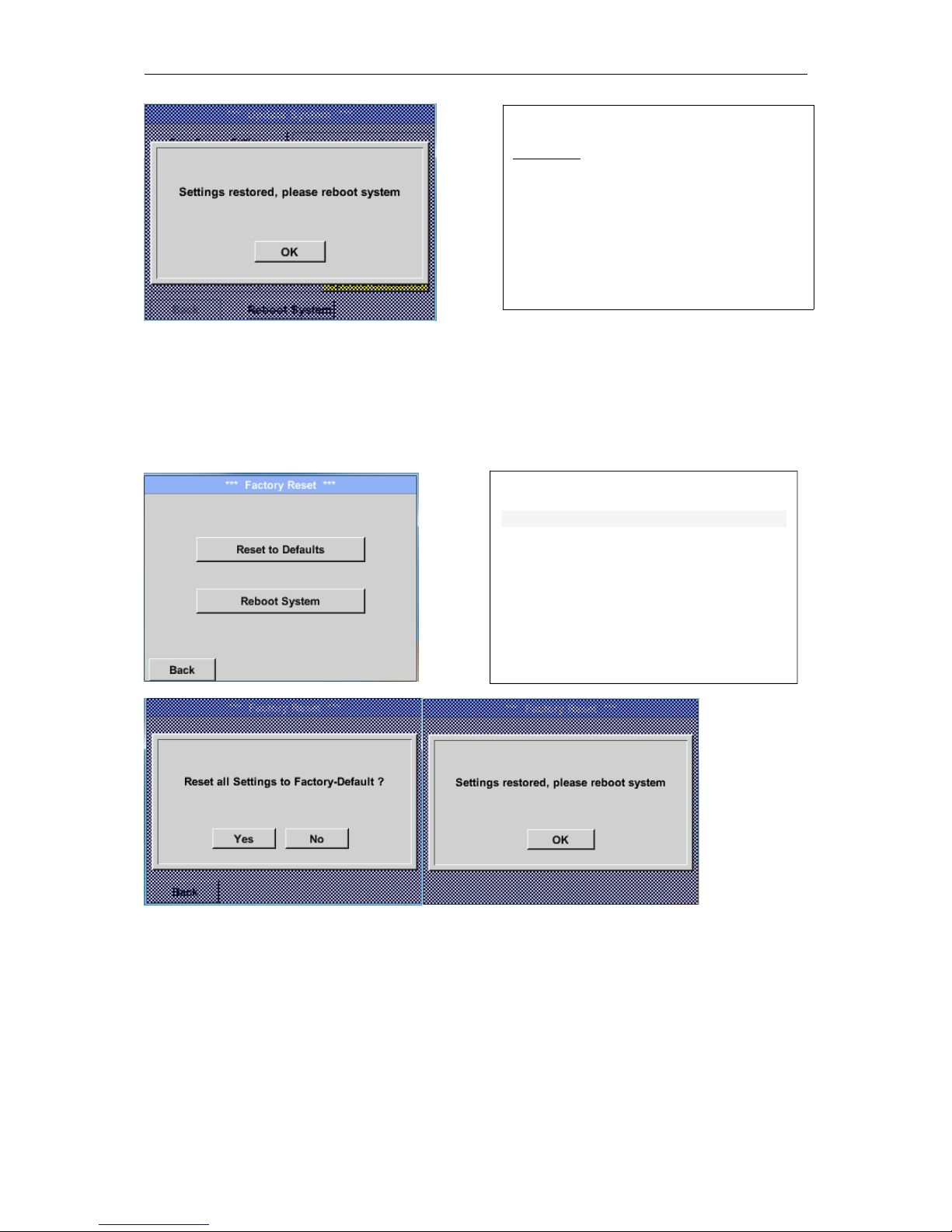
8.3.2.1.4.5 Factory Reset
Main menu Settings Device settings Factory ResetReset to Defaults
41
Important:
If the channel and system settings have
been reset you have to push OK and then
the Reboot system button.
If necessary or required, by pressing the
Reboot System-button the DP 500 could be
rebooted.
Page 42
DP500
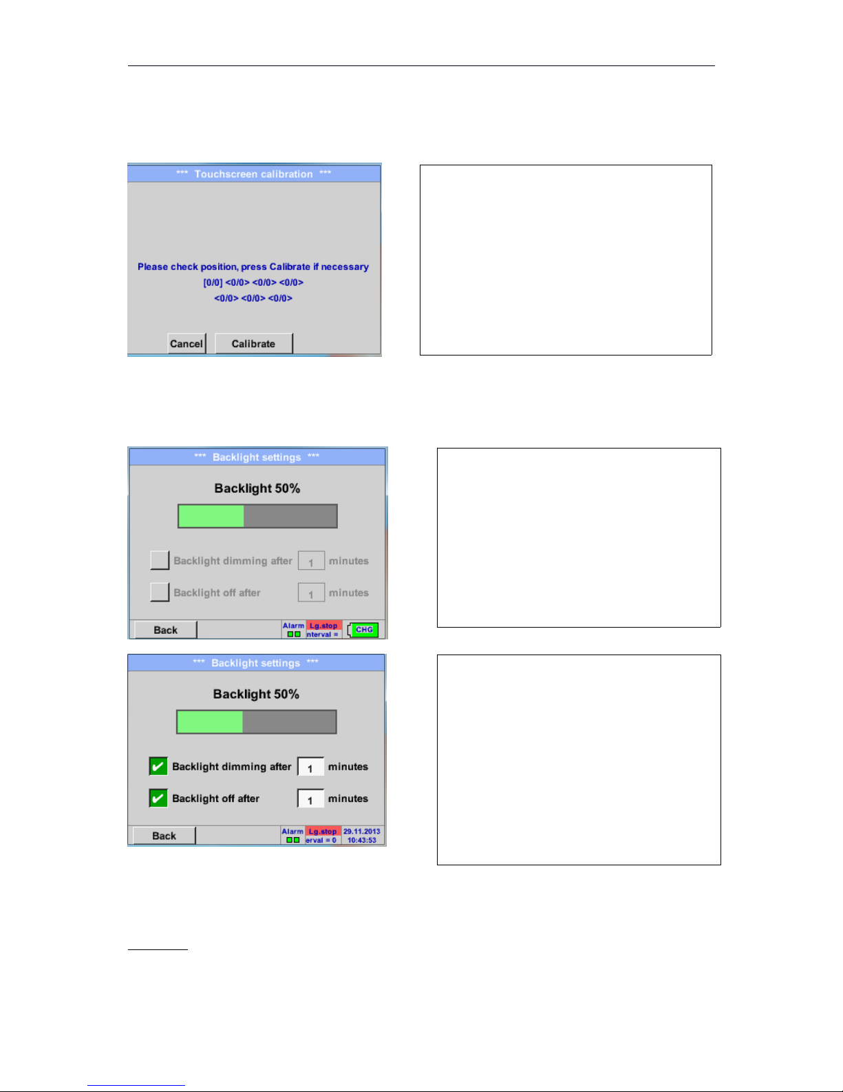
8.3.2.1.4.6 Calibrate touch-screen
Main menu Settings Device settings calibrate touchscreen
8.3.2.1.5 Set backlight
Hauptmenü Einstellungen Helligkeit
Remark:
At the first touch, the Backlight in our example is reset to 50%, after that a "normal" function
operation is possible.
Important:
If the Backlight dimming after button is not activated, then the Backlight stays permanently on,
in the currently set brightness.
42
If necessary, the touch-screen calibration can
be changed here.
Push Calibrate and it appears, 1. left above,
2. bottom right and 3. in the middle, a
calibration cross that must be pushed
consecutively.
If the calibration finished and the touch-screen
display averaged, you can confirm with OK.
Is this not the case, so you can repeat the
calibration with the help of the Cancel and
Calibrate buttons.
Here you adjust the desired Backlight
(15-100%) of the display directly.
e.g. Backlight to 50 %
With the help of the Backlight dimming after
button, after a definable time interval (here
after 15 minutes), the Backlight can be
reduced to the minimum.
In addition, for a longer battery runtime, the
backlight could be switched off completely
after the defined time (here 1 minutes) by
pressing backlight off after button.
As soon as the dimmed screen is operated
again, the Backlight is committed
automatically on the last set value before
dimming.
Page 43
DP500
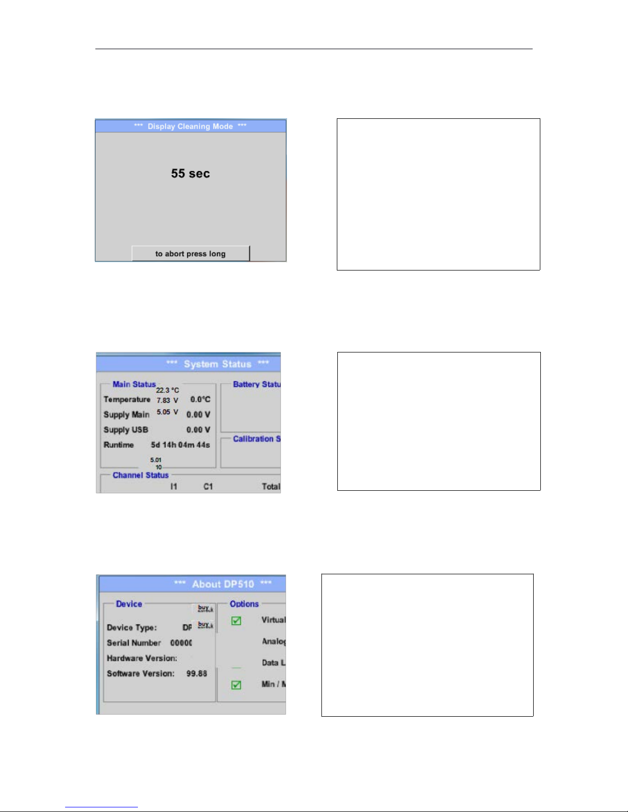
8.3.2.1.6 Cleaning
Main menu Settings Cleaning
8.3.2.1.7 System-Status
Main menu Settings System-Status
8.3.2.1.8 About DP 500
Main menu Settings About DP 500
43
This function can be used for cleaning the
touch panel during running measurements.
If one minute is not enough time to clean,
the process can be repeated at any time.
Is the cleaning faster finished, then you can
push the to abort press long button (for one
or two seconds) to cancel.
The function System Status offers an
overview, fitting voltages and currents on
the individual and the entire channel, as well
as the power supply of the power supply
unit.
By the Runtime, you always know how long
the DP 500 was in total in operation
Brief description of the Hardware and
Software Version, as well as the Serial
Number of the DP 500.
Page 44
DP500
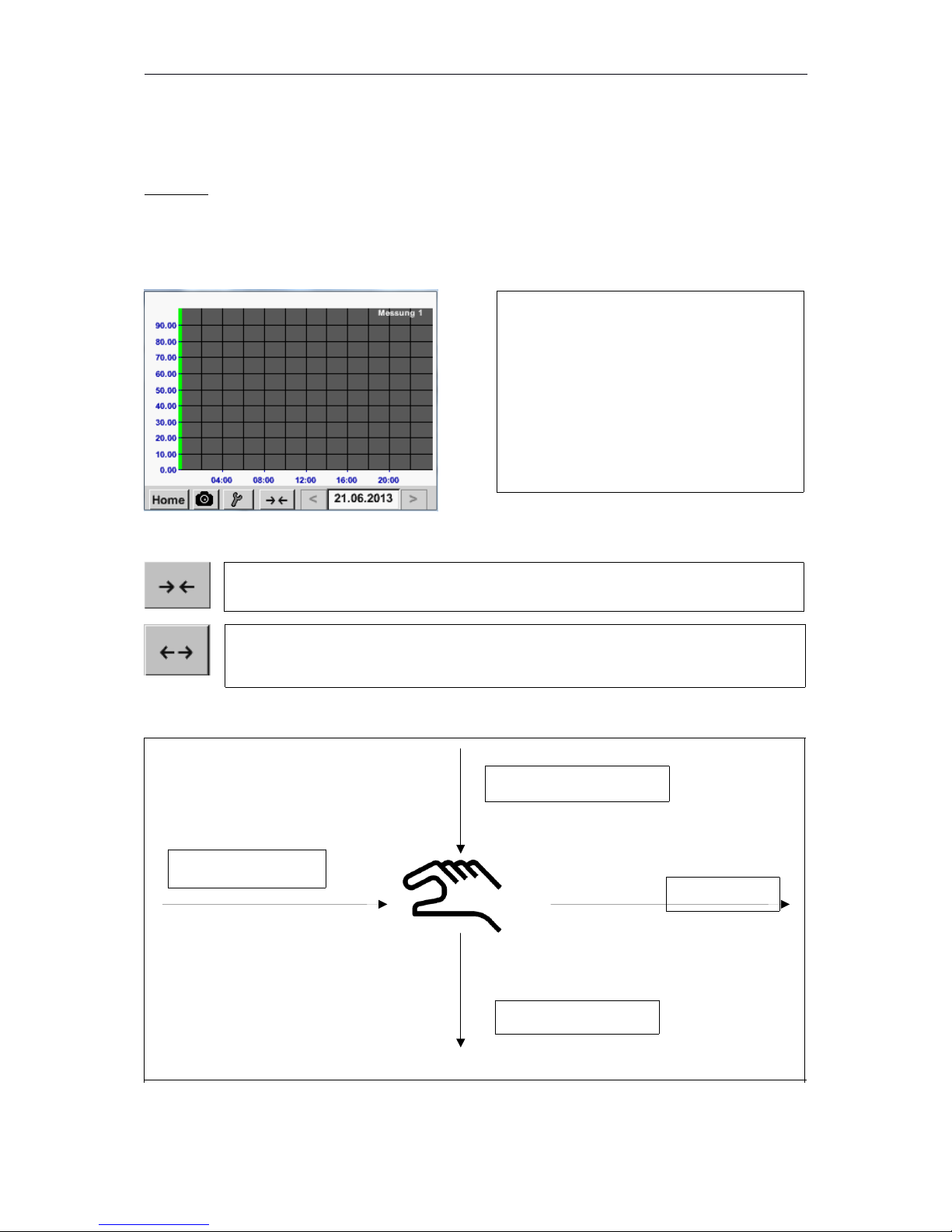
8.3.2.2 Chart
Main menu Chart
Attention:
In the Chart there can be represented only records that have already finished!
Current records can be seen in Chart/Real time values.
(See chapter 10.3.2.3 Chart/real time values)
Zoom and scroll options in the time domain of the Chart:
Additional zooming and scrolling options in Chart and Chart/Real time values
Main menu Chart Date description field
44
Running measurement, there are no values
represented!
time earlier
Maximal an entire day can be represented (24h).
The smallest possible range is represented, depending on the time interval of the
recording.
Bigger period of time
Time later
Smaller period of time
Page 45
DP500
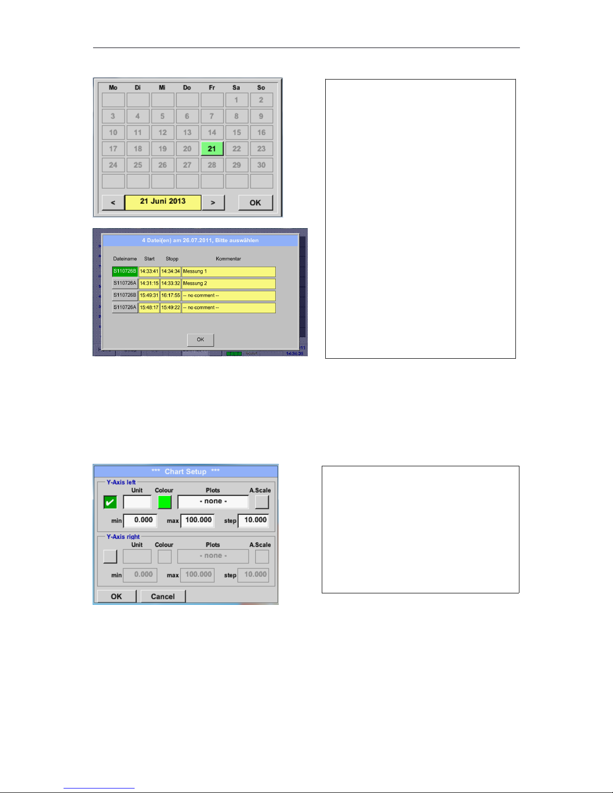
Main menu Chart Setup
In the Setup, you can make up to four different y-axis labels and in addition choose a Unit, the grid
(min, max, step) and several channels (Plots) and a Colour.
45
By pushing the date description field
(center bottom) the calendar, from which
the appropriate date can be selected
conveniently, appears.
Stored measuring data can be select here
by time (START and STOP), Comment
and File name (contains English date).
The y-axis left.is already enabled, you
can choose a Colour for it.
Remark:
Grid setting is already possible at this
point, but later when a record is
selected it is more reasonable!
Page 46
DP500
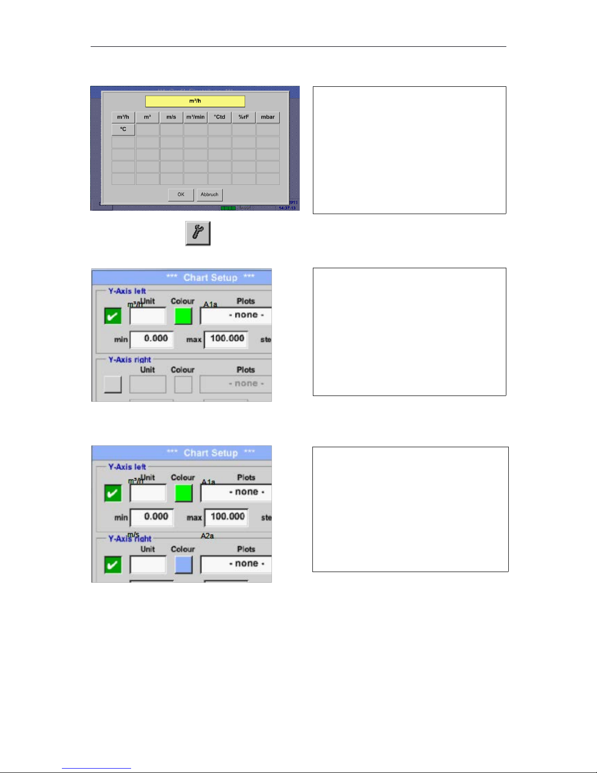
Main menu Chart Setup Unit description field
Main menu Chart
In the same way the remaining y-axes can be labelled!
46
Select the Unit of the represented recording
from the menu.
Now, the grid can be set with min, max, and
step.
By pushing the A.Scale-button a calculated
auto-scaling will be defined.
Two different grid settings with various Units
and Colours.
Page 47
DP500
Main menu Chart
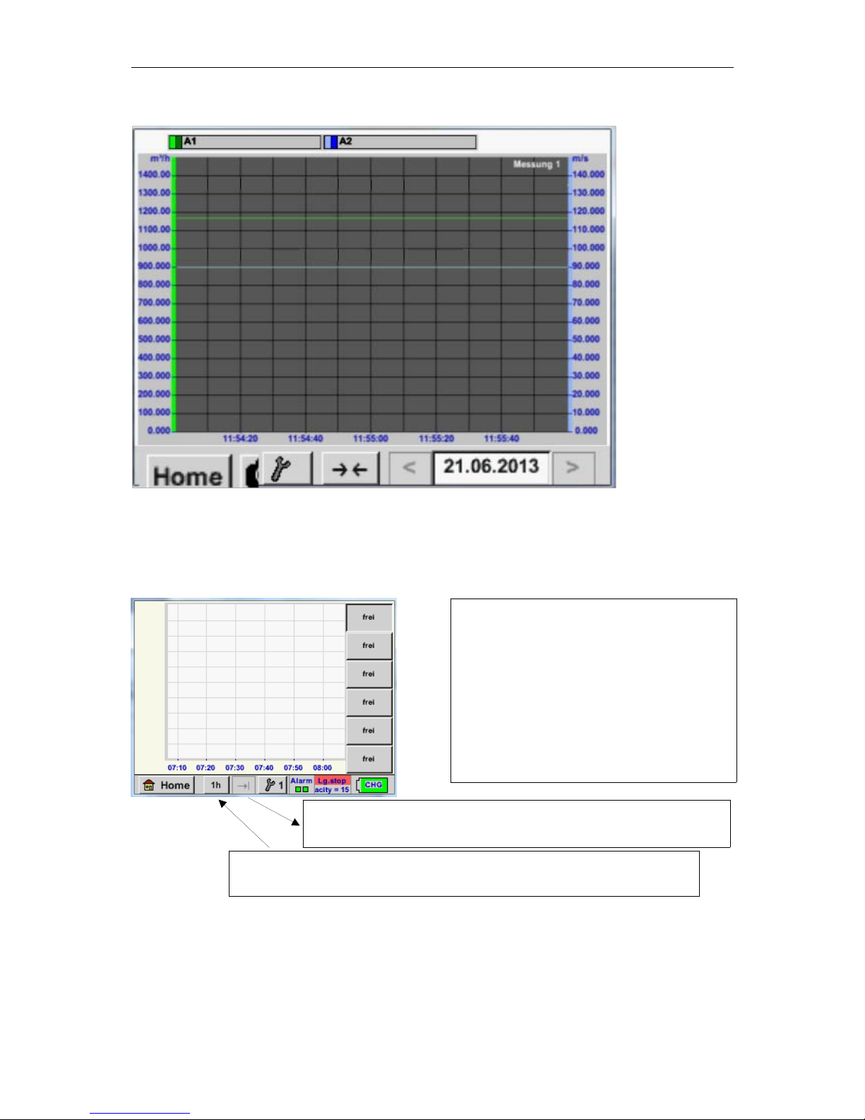
8.3.2.3 Chart / Real time values
Main menu Chart/Real time values
47
One or more channels for the recording and
presentation of measured data can be
selected here, such as a dew point sensor or
several different sensors.
After pushing this button currently recorded measurement data in the
current time range are represented.
Quick access to predefined time periods 24 h, 8 h, 1 h, 15 min and 2 min.
At the push of a button the chart for the selected time range is displayed.
Page 48
DP500
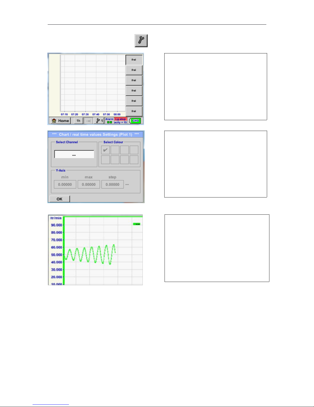
Main menu Chart/Real time values #1- #6
In the same way the remaining setups can be set!
48
In this menu item, up to twelve channels
(depending on the version of the DS 400)
can be activated at the same time and
viewed in Main Chart/Real time values.
Here the channel C1 chosen.
For each channel, you can select a value to
be represented in the Chart and one to
display (2. values).
In addition, it can be set, like in Main
Chart, a colour and the grid (min, max, step)
of the y-axis.
Channel C1:
Elected the flow as Chart
.
If several channels are logged, all charts will
be displayed, but there is only the y-axis of
the selected channel visible.
If there is no grid entered in the setup ,min
will be 0, max 100 and step 10
Page 49
DP500
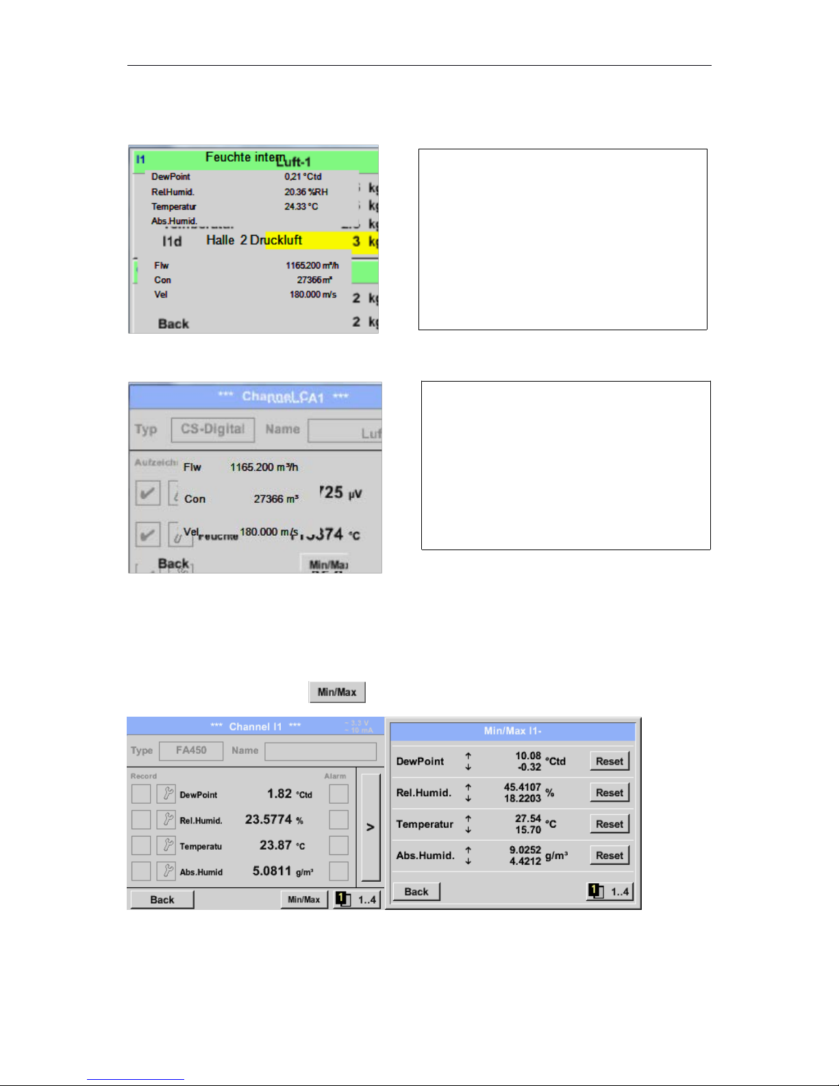
8.3.2.4 Channels
Main menuChannels
Main menu Channels C1
8.3.2.4.1 Min/Max Function
This feature allowsto read out theminimum or maximumvalues of thecurrentmeasurement for each
connected sensor.Start of recordingisimmediately after setting of the sensor, but there is always
thepossibilityto resetthe Min andMaxvalues.
Main menu Channels I1
49
The overview of Channels shows the current
measured values of all connected sensors.
Exceeds or falls below the set alarm limits, the
respective measured value flashes yellow
(alarm 1) or red (alarm 2).
.
Each channel can be selected and the settings
viewed and checked, but no changes can be
made here.
Remark:
Please, make changes in the Settings!
Page 50
DP500
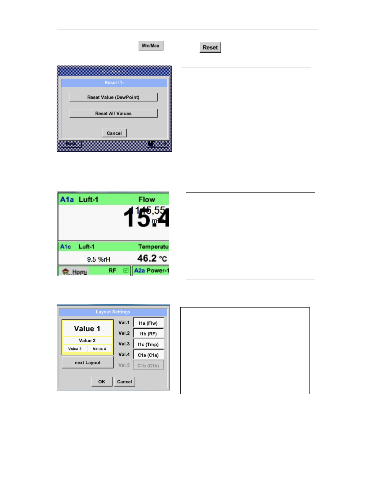
Main menu Channels I1 Dew point
8.3.2.5 Real time values
Main menu Real time values
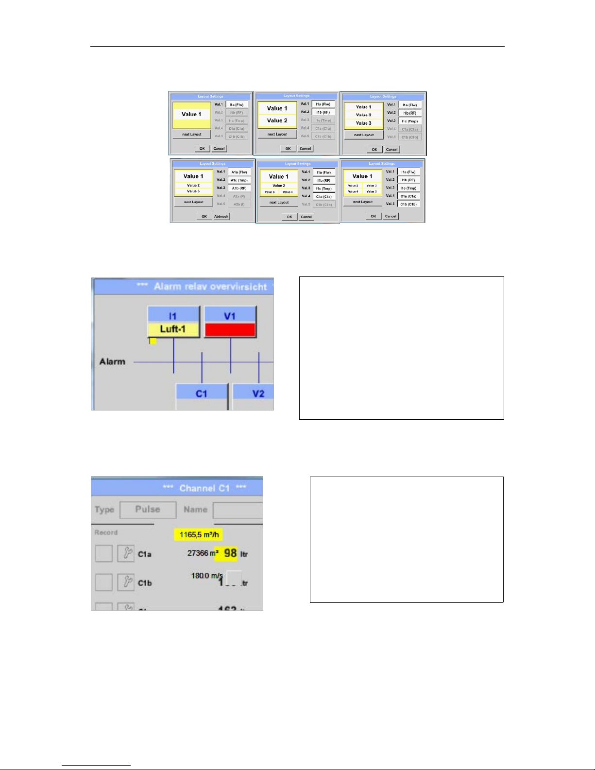
Main tmenu Real time values Setup next Layout
50
It is possible to reset a singlemeasurement
value, here it is the dew pointor ifneeded to
reset allminimum and maximumvalues of the
sensor.
For resetting the single value the Reset
Value –Button for all Min/Max-Values the
Reset All Values –Button has to be pressed.
The view Real time values allows to display of
1 to 5 free definable measurement values.
By exceeding the upper- or lower alarm levels
the respective measurement value flashes
yellow for Alarm-1or red for Alarm-2.
Remark:
Changes for display settings have to be done
in the Setup menu!
Here, by pressing next Layout –button it is
possible to select the wanted layout.
You can choosebetween6
differentlayoutsshowing1-5 measurements.
seebelow.
The values tobe displayed could be selected in
the Val.1 to Val.5 description fields.
Page 51
DP500
Different variantes :
8.3.2.6 Alarm overview
Main menu Alarm-Overview
Here Alarm-1 for Channel I1!
Main menu Alarm-OverviewC1
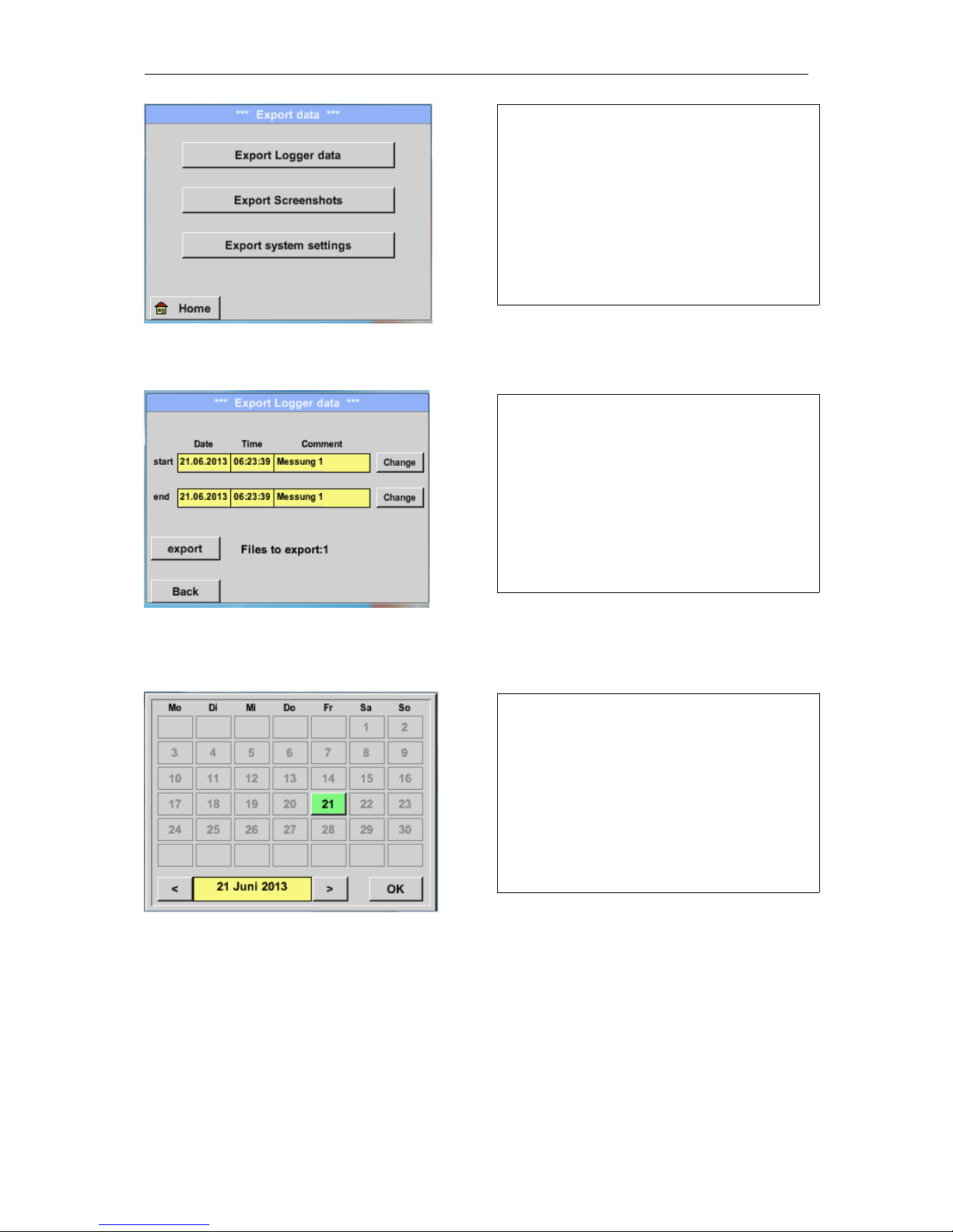
8.3.2.7 Export Data
Recorded data can be transferred to a USB stick, by using Export Data.
Main menu Export data
51
In the Alarm overview, you can immediately
see whether there is an alarm 1or alarm 2.
You can see also in other menu items:
Main Real time values and
Main Settings Sensor settings
The channel name will appear yellow invers
(alarm 1) or inverse red (alarm 2).
In addition, you can see which popup had been
set for the channel as the alarm 1or alarm 2.
Like in Main Real time values,individual
channels can be selected here,
to detect which and how much the value has
exceeded or below the alarm range.
Remark:
The alarm parameters can be set and/or
modified here.
Page 52
DP500
Main menu Export data Export Logger data
Main menu Export data Export Logger data Change
52
With Export Logger data and Export system
settings the recorded measurement data and
saved settings can be transferred to a USB
stick.
Use the Change buttons to adjust a period
between start and end. Stored measurement
data in this period are exported
The selected date is always green, and the
date numbers of the Sundays are red, like in
the calendar.
On days, where measurement data were
recorded, the date numbers are optical
highlighted.
Page 53
DP500
Main menu Export data Export Logger data export
The measurement data of the selected period are exported to a USB stick.
Main menu Export data Export system settings
By using Export system settings, all existing sensor settings can be exported to a USB stick.
53
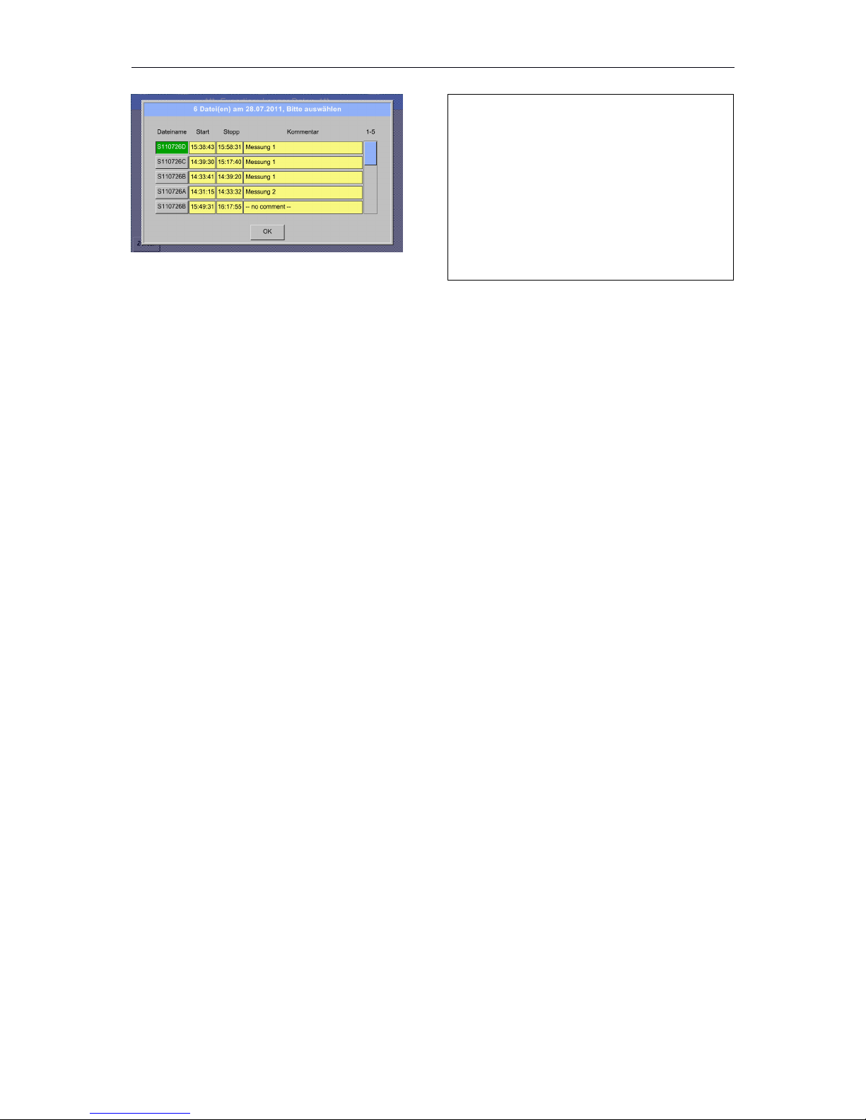
If there have been recorded several
measurements on the same date, they
appear after the date selection with OK.
Now a recording can be selected
comfortable.
Page 54

Page 55

Page 56

NT - DP500 – 12/05/17 - RCS (24) Périgueux 349 282 095 Non-contractual document – We reserve the right to modify the characteristics of our products without prior notice.
 Loading...