

DBM610
AIRFLOW METER
Rugghölzli 2
CH - 5453 Busslingen
Tel. +41 (0)56 222 38 18
Fax +41 (0)56 222 10 12
mailbox@sentronic.com
www.sentronic.com
Produkte, Support und Service
SEN
TRONIC
AG

Rugghölzli 2
CH - 5453 Busslingen
Tel. +41 (0)56 222 38 18
Fax +41 (0)56 222 10 12
mailbox@sentronic.com
www.sentronic.com
Produkte, Support und Service
SEN
TRONIC
AG

Table of contents
1. Introduction..........................................................................................................................................5
1.1. Key points............................................................................................................................................... 5
1.2. Technical features................................................................................................................................... 5
1.3. General technical features...................................................................................................................... 6
2. Presentation of airflow meter..............................................................................................................7
2.1. Base........................................................................................................................................................ 7
2.2. Grid......................................................................................................................................................... 8
2.3. Electronic housing................................................................................................................................... 8
2.3.1. Airflow meter mode........................................................................................................................................... 9
2.3.2. Micromanometer mode..................................................................................................................................... 9
2.3.3. Power supply of electronic housing................................................................................................................... 9
2.4. Hoods.................................................................................................................................................... 10
3. Mounting the airflow meter................................................................................................................10
3.1. Mounting of frame................................................................................................................................. 10
3.2. Setting of the cloth................................................................................................................................. 11
3.3. Setting of rods....................................................................................................................................... 12
4. Using DBM610 in airflow meter mode..............................................................................................12
4.1. Starting up............................................................................................................................................. 12
4.2. Configure the airflow meter................................................................................................................... 12
4.2.1. Set the correction coefficient........................................................................................................................... 12
4.2.2. Set measurement units................................................................................................................................... 13
4.2.3. Set a damping................................................................................................................................................. 13
4.2.4. Activate or deactivate standardized airflow..................................................................................................... 13
4.3. Perform averages.................................................................................................................................. 13
5. Using DBM610 in micromanometer mode........................................................................................14
5.1. Starting up............................................................................................................................................. 14
5.2. Set the micromanometer....................................................................................................................... 14
5.2.1. Select the airflow sensor................................................................................................................................. 14
5.2.2. Set the surface................................................................................................................................................ 14
5.2.3. Set measurement units................................................................................................................................... 15
5.2.4. Set a damping................................................................................................................................................. 15
5.2.5. Activate or deactivate the solenoid valve........................................................................................................ 15
5.2.6. Set the thermocouple type.............................................................................................................................. 15
5.2.7. Set the compensation temperature................................................................................................................. 15
5.2.8. Activate or deactivate the standardized airflow............................................................................................... 15
5.3. Activate or deactivate air velocity and airflow........................................................................................16
5.4. Perform averages.................................................................................................................................. 16
5.4.1. Automatic average.......................................................................................................................................... 16
5.4.2. Point/point average......................................................................................................................................... 16
5.4.3. Point/point automatic average......................................................................................................................... 16
5.5. Perform an autozero............................................................................................................................. 17
6. Manage dataset recordings..............................................................................................................17
6.1. Get to recorded datasets....................................................................................................................... 17
6.2. Delete recorded datasets...................................................................................................................... 17
7. Set the device....................................................................................................................................17
7.1. Set date and time.................................................................................................................................. 17
7.2. Set language......................................................................................................................................... 17
7.3. Set automatic shut-off........................................................................................................................... 18
7.4. Set brightness....................................................................................................................................... 18
7.5. Set contrast........................................................................................................................................... 18
7.6. Activate or deactivate beep................................................................................................................... 18
8. Information about the device.............................................................................................................18
8.1. Identification.......................................................................................................................................... 18
8.2. Calibration............................................................................................................................................. 18
8.3. After sales service................................................................................................................................. 18
Rugghölzli 2
CH - 5453 Busslingen
Tel. +41 (0)56 222 38 18
Fax +41 (0)56 222 10 12
mailbox@sentronic.com
www.sentronic.com
Produkte, Support und Service
SEN
TRONIC
AG

Rugghölzli 2
CH - 5453 Busslingen
Tel. +41 (0)56 222 38 18
Fax +41 (0)56 222 10 12
mailbox@sentronic.com
www.sentronic.com
Produkte, Support und Service
SEN
TRONIC
AG

1. Introduction
DBM610 airflow meter allows control and balancing of airflow in air conditioning system. Thanks to the interchangeable
hoods, the airflow can be used on any type of grids or diffusers in air supply or exhaust.
Easy to handle, lightweight, it allows accurate, sturdy and fast measurements.
It is supplied in standard with a 610 x 610 mm hood. Four other dimensions are available as options :
• 1020 x 1020 mm
• 720 x 720 mm
• 720 x 1320 mm
• 420 x 1520 mm
These hoods are airtight and have a transparent part on each side, allowing the user to see through the vent and
ensure that the hood is in a good position. The rods, made of fiberglass, provide a sturdiness of hoods.
The measurement grid, attached to the base, allows the measurement through 48 points all over the surface of the
grid. Measurement is performed using a differential pressure sensor, calibrated and compensated in atmospheric
pressure and temperature.
The measuring unit of the airflow meter, removable, can be used as a micromanometer.
Real addition to airflow measurement, this instrument allows, by connecting a Pitot tube, to measure airflow velocity in air
duct or, by connecting two silicone tubes, to check filter fouling of air station.
1.1. Key points
• Measuring range from 40 to 3500 m3/h
• Quick and simple hood changes
• Software for data processing on computer (datalogger 10)
• Sturdy, lightweight and easy to handle
• Removable measuring unit
• Interchangeable hoods
1.2. Technical features
• Airflow :
Measuring range................from 40 to +3500 m3/h
Accuracy............................3% of measuring ±10 m3/h
Resolution..........................1 m3/h
• Temperature (on the base)
Measuring range................ from 0 to 50 °C
Accuracy............................2% of measuring ±0.1 °C
Resolution..........................0.1°C
• Thermocouple Temperature (on the micromanometer)
Thermocouple type...........K, J, T, S
Measuring range................K : from -200 to 1300°C
J : from -100 to 750°C
T : from -200 àto400°C
S : from 0 to 1760°C
Resolution..........................K : ±1,1°C or ±0,4% of reading value
J : ±0,8°C or ±0,4% of reading value
T : ±0,5°C or ±0,4% of reading value
S : ±1°C or 0,4% of reading value
• Pressure :
Measuring range................from -2500 to +2500 Pa
Accuracy............................±0,2% of measuring ±2Pa
Resolution........................from 0.01 to 0.1 Pa
Rugghölzli 2
CH - 5453 Busslingen
Tel. +41 (0)56 222 38 18
Fax +41 (0)56 222 10 12
mailbox@sentronic.com
www.sentronic.com
Produkte, Support und Service
SEN
TRONIC
AG

1.3. General technical features
Display
Large graphic back-lighted LCD
Sizes : 86 x 51 mm
Connectors
ABS connectors, Ø 7 x 4 mm
Housing
Shock-proof made of ABS, IP54 protection
Keypad
12 keys
Conformity
Electromagnetical compatibility (NF EN 61326-1 guideline)
Power supply
4 alkaline batteries LR6 - Rechargeable battery Li-ion, 3.7 V 4400 mhA (optional)
Environment
Neutral gases
Operating temperature
From 0 to +60 °C
Storage temperature
From -20 to +70 °C
Auto shut-off
Adjustable from 0 to 120 min
Weight
3600 g
Languages
French, English
Rugghölzli 2
CH - 5453 Busslingen
Tel. +41 (0)56 222 38 18
Fax +41 (0)56 222 10 12
mailbox@sentronic.com
www.sentronic.com
Produkte, Support und Service
SEN
TRONIC
AG
2. Presentation of airflow meter
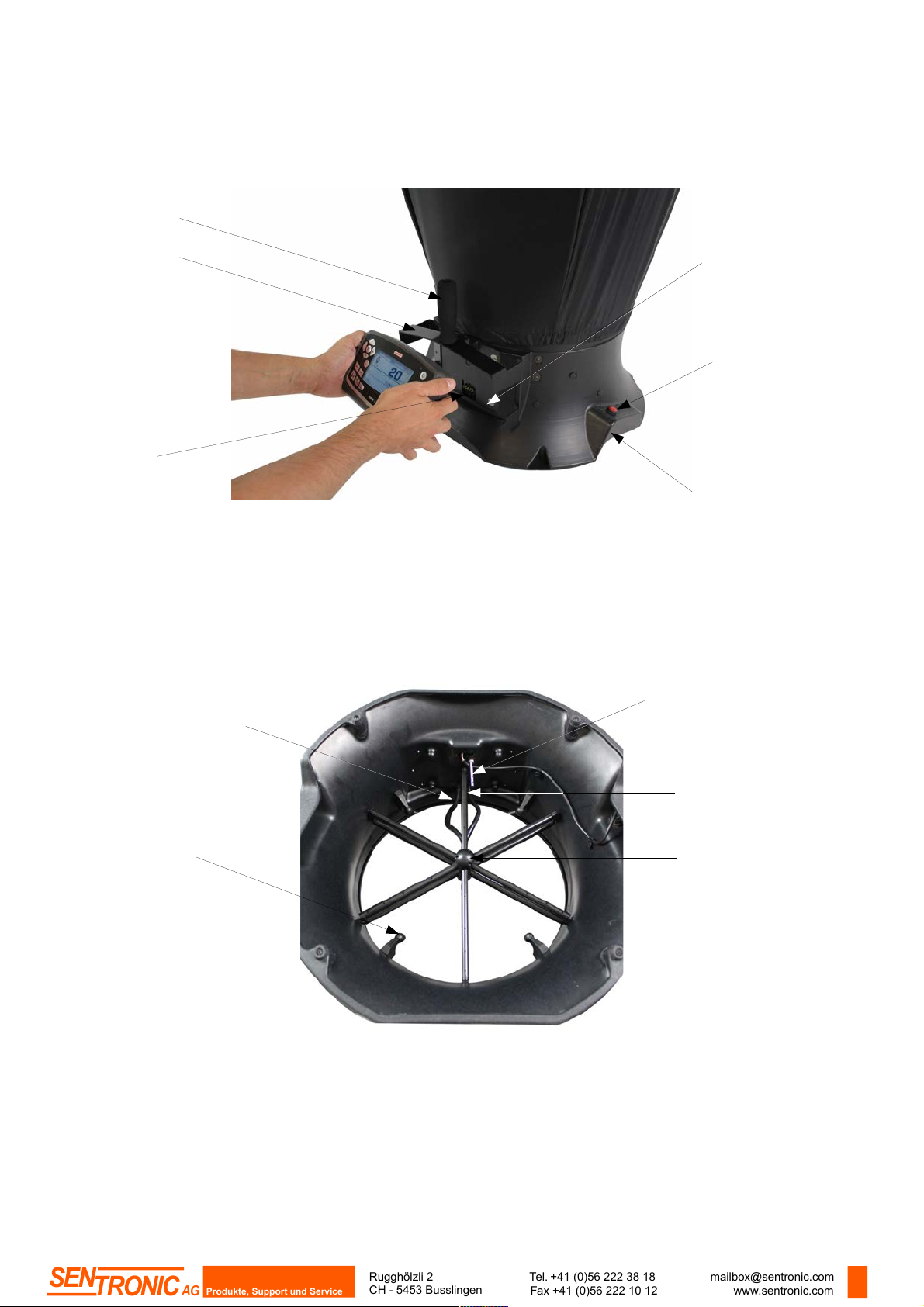
2.1. Base
• Outside of the base :
• Inside the base :
7
Carrying handle
Protective cover
Location for the
electronic housing
Integrated ergonomic handle
Button of point/point
measurement start
Electronic card
Silicone tube for pressure
routing
Receipt cup hood rods
Measurement grid
Temperature probe
Two pressure connectors
Rugghölzli 2
CH - 5453 Busslingen
Tel. +41 (0)56 222 38 18
Fax +41 (0)56 222 10 12
mailbox@sentronic.com
www.sentronic.com
Produkte, Support und Service
SEN
TRONIC
AG

2.2. Grid
The measurement grid is fixed to the base in 6 points and is made up of the following elements :
• 1 core made up of two chambers (for total pressure and for static pressure)
• 12 tubes tapped of 4 holes
• 2 pressure connectors
The measurement grid allows to measure differential pressure. It takes into account atmospheric pressure and temperature
compensation and works automatically in supply or exhaust.
2.3. Electronic housing
Features :
• Shock-proof made of ABS
• IP54 protection
• Large graphic back-lighted LCD (86 x 51 mm)
• Auto shut-off adjustable from 0 to 120 min
• Manual or automatic autozero
• Removable housing for micromanometer function
• 4 magnets at the back allow the mounting on the base (airflow meter mode)
• 2 pressure plugs allow to set the housing on the base and the connection of silicone tube for the measurement with
a Pitot tube
• 1 thermocouple plug on the top of the housing (micromanometer mode)
8
Central core
Threaded holes
2 pressure
connectors
Validation button
Front side
On/Off button
Save button
Average button
Autozero button
Hold button
Menu button
Escape button
Low battery signal
Back side
Pressure plugs
Magnet
Thermocouple
plug
Battery trap
Rugghölzli 2
CH - 5453 Busslingen
Tel. +41 (0)56 222 38 18
Fax +41 (0)56 222 10 12
mailbox@sentronic.com
www.sentronic.com
Produkte, Support und Service
SEN
TRONIC
AG

2.3.1. Airflow meter mode
In airflow meter mode, the device has following functions :
• Simultaneous display of airflow, pressure and temperature
• Automatic airflow direction (supply or exhaust)
• Automatic average and point by point average
• HOLD function (measurement is fixed)
• USB interface for PC operation
• Languages choice
2.3.2. Micromanometer mode
In micromanometer mode, the device has following functions :
• Measurement of air velocity with Pitot tube S, L or Debimo blades
• Measurement of thermocouple temperature
• Automatic average and point by point average
• HOLD function (measurement is fixed)
• USB interface for PC operation
• Languages choice
2.3.3. Power supply of electronic housing
The airflow meter is supplied in standard with 4 batteries type AA LR6 1.5V. Rechargeable batteries and Li-Ion battery are
available as options.
To replace batteries (rechargeable or not) :
➢ Remove the batteries cover then used batteries.
➢ Disconnect the batteries support.
➢ Replace batteries then reconnect the support.
➢ Replace the batteries cover.
To put the Li-Ion battery (optional) :
➢ Remove the batteries cover then the batteries support.
➢ Connect the battery.
➢ Replace the batteries cover.
9
Respect the connections (see below).
Connection for LR6 batteries
support (rechargeable or not)
Connection for
Li-Ion battery
Back view
Side view
Connection for
main
adapter/charger
USB connection
Rugghölzli 2
CH - 5453 Busslingen
Tel. +41 (0)56 222 38 18
Fax +41 (0)56 222 10 12
mailbox@sentronic.com
www.sentronic.com
Produkte, Support und Service
SEN
TRONIC
AG

To load the device :
• If the device is on Li-Ion battery : connect the main adapter/charger on the side of the device
• If the device is on rechargeable batteries : remove batteries load them an external charger
It is also possible to load the electronic housing with the main adapter/charger supplied with Li-Ion battery.
2.4. Hoods
3. Mounting the airflow meter
3.1. Mounting of frame
To mount the different optional frames of airflow meter, just fit together the elements of the frame.
Stickers numbered from 1 to 8 are stuck on each end of the elements :
Example with 720 x 720 mm frame :
10
Transparent mica allowing a good
visibility and making easy the position
of the hood
Elastic to hold the
hood on the base
Frame with a foam to ensure a
good airtight with ceiling
Frame rods
1
1
2
2
3
3
4
4
5
5
6
6
7
7
8
8
Step 1
Cloth of the hood
Rugghölzli 2
CH - 5453 Busslingen
Tel. +41 (0)56 222 38 18
Fax +41 (0)56 222 10 12
mailbox@sentronic.com
www.sentronic.com
Produkte, Support und Service
SEN
TRONIC
AG

3.2. Setting of the cloth
Before set the cloth on the frame, frame must be mounted.
➢ First, insert a corner of the frame inside a corner of the cloth.
➢ Insert the opposite corner of the frame in the corresponding corner of the cloth.
The color mark must be in the middle of the frame side. (1).
➢ Press on the corresponding side of the cloth to put it in the rail of the frame.
➢ Proceed the same way for the rest of the cloth.
When the cloth is fixed on the frame :
➢ Place the cloth on the base.
The mark on the cloth and the Velcro tape are opposed to the carrying handle of the base.
➢ Put the elastic of the cloth around the DBM base.
➢ Tighten the Velcro tape of the cloth on the base.
➢ If necessary, turn the cloth to match the mark of the cloth with the mark on the base.
11
Zoom on elastic of the cloth around the base
Zoom on the back of the
base with tightened Velcro
tape
Elastic to be set
around the base
Mark on the cloth
Mark on the
base
Cloth on the base
1
Rugghölzli 2
CH - 5453 Busslingen
Tel. +41 (0)56 222 38 18
Fax +41 (0)56 222 10 12
mailbox@sentronic.com
www.sentronic.com
Produkte, Support und Service
SEN
TRONIC
AG

3.3. Setting of rods
➢ Place the 4 holding rods inside the hood.
➢ Take a rod and insert the rounded end of the rod in the reception holding cup of the base.
➢ Slightly bend the rod and insert the flat end of the rod on the opposite corner of the holding cup.
➢ Proceed the same way for the three other rods.
Note :
• The airflow meter has 4 rods. Some of them have extensions (airflow meters of 1020 x 1020, 720 x 1320 and
420 x 1520 dimensions ). It is necessary to put the extensions on each rod before put them in the device.
• Rods are placed face-to-face ; they intersect only on the following sides : housing side and cloth mark side.
4. Using DBM610 in airflow meter mode
4.1. Starting up
When the airflow meter is correctly set and the housing mounted on the base,
press On/Off button :
The device directly displays the data below (see photo) :
• airflow
• delta pressure
• temperature
The solenoid valve is active and flaps every second.
4.2. Configure the airflow meter
➢ Press " Menu " button.
➢ Press " Left arrow " or " Right arrow " key until reach " Configuration ".
➢ Press " Ok " button.
The sub-menu " Configuration " appears with following data :
• Correction coefficient : allows to set the correction coefficient
• Units : allows to set unit for airflow, pressure and temperature
• Damping : allows to smooth the measurement and avoid unwanted
• Standard airflow : allows to activate or not the standardized airflow as per DIN1343 standard
4.2.1. Set the correction coefficient
➢ Go to " Correction coef " line then press OK button.
➢ Select the required correction coefficient with up and down arrows then press OK.
Screen displays the selected coefficient. It is possible to modify it with arrow keys.
➢ Press OK to validate and back to " Configuration " menu.
12
Rounded end in the
holding cup
Rounded end in
the holding cup
Flat end in the
opposite corner
Rugghölzli 2
CH - 5453 Busslingen
Tel. +41 (0)56 222 38 18
Fax +41 (0)56 222 10 12
mailbox@sentronic.com
www.sentronic.com
Produkte, Support und Service
SEN
TRONIC
AG

4.2.2. Set measurement units
➢ Go to " Unit " line then press OK key.
➢ Go to the required line (airflow, temperature or pressure) then press OK.
➢ Select unit with up and down arrows then press OK.
Available units are :
• Airflow : m3/h, L/s, cfm
• Pressure : Pa, mmH2O, mmHg, inWg
• Temperature : °C, °F
➢ Press Esc to quit " Units " sub-menu and back to " Configurations " menu.
4.2.3. Set a damping
➢ Go to " Damping " line then press OK.
➢ Select the required coefficient (from 0 to 9) then press OK.
4.2.4. Activate or deactivate standardized airflow
The standardized airflow allows to have a calculation of airflow as per DIN 1343 standard.
➢ Go to " Standard airflow" then press OK.
➢ Select ON or OFF with up and down arrows then press OK.
When standardized airflow is activated, " NORMO " indication is shown on screen on the left of time.
4.3. Perform averages
During measurement, it is possible to perform an automatic average.
➢ Press " Moy/Avg " button.
➢ Press OK or the red button on the right of the base to launch measurement.
Measurement duration appears at the lower right of the screen.
➢ Press OK or the red button on the right of the base to display the results when required measurement duration is
reached.
➢ Press up and down arrows to get to results of the different parameters.
Screen displays results on two columns :
• 1st column : measurement results
• 2nd column : results average ; here, values will be the same in both columns.
➢ Press OK or the red button on the right of the base to go to measurement screen.
➢ Press OK again or the red button on the right of the base to launch a new measurement.
➢ Press OK again or the red button on the right of the base to display results when required measurement duration is
reached.
➢ Press up and down arrows to get to results of the different parameters.
Screen displays results on two columns :
• 1st column : measurement results
• 2nd column : results average of the 1st point and 2nd point and airflow aggregate.
During measurement :
➢ Press " Esc " to cancel and back to measurement screen.
On measurement screen :
➢ Press " Esc " to cancel and not include these results. It will be possible to launch a new measurement.
➢ Press " Save " to save results.
13
Rugghölzli 2
CH - 5453 Busslingen
Tel. +41 (0)56 222 38 18
Fax +41 (0)56 222 10 12
mailbox@sentronic.com
www.sentronic.com
Produkte, Support und Service
SEN
TRONIC
AG

5. Using DBM610 in micromanometer mode
5.1. Starting up
The device is disconnected from airflow meter base.
➢ Press On/Off button.
The device directly displays data below (see photo) :
• Airflow
• Air velocity
• Pressure delta
• Temperature compensation
• Type of airflow sensor used and size of the surface
5.2. Set the micromanometer
➢ Press " Menu " button.
➢ Press " Left arrow " or " Right arrow " button until reach " Configuration ".
➢ Press " Ok " button.
The sub-menu " Configuration " appears with following data :
• Airflow sensor : allows to select the airflow sensor used for the measurement : Pitot tube L, S,
Debimo blade or Coefficient
• Surface : allows to define the of surface and its size
• Units : allows to define unit for airflow, air velocity, pressure and temperature
• Damping : allows to smooth the measurement and avoid unwanted variations
• Solenoid valve : allows to activate or not the solenoid valve
• Thermocouple : allows to set the thermocouple type : K, J, T ou S
• Temp Compen : allows to set the compensation temperature
• Standard airflow : allows to activate or not the standardized airflow as per DIN1343 standard
5.2.1. Select the airflow sensor
➢ Go to " Airflow sensor " line then press OK.
➢ Press OK on the " Element ".
➢ Select the airflow sensor (Pitot tube L, Pitot tube S, Debimo blade or Coefficient) with up arrow and down arrow
then press OK.
It is also possible to select the corresponding coefficient to the airflow sensor :
➢ Go to " Airflow sensor " line then press OK.
➢ Press OK on the " Coefficient ".
➢ Select the coefficient from 0 to 9 with up arrow and down arrow then press OK.
Screen displays the required coefficient. It is possible to modify it with arrow buttons.
➢ Press OK to back to " Airflow sensor " sub-menu .
➢ Press Esc to quit " Airflow sensor " sub-menu and back to " Configurations " menu.
5.2.2. Set the surface
Set length and width of the surface :
➢ Go to " Surface " and press OK.
➢ Go to " Type " line then press OK.
➢ Press OK on Lxl line.
➢ Select the required dimensions with up and down arrows then press OK.
➢ If necessary, modify the length then the width with arrows then press OK (if no modification, just press OK).
14
Rugghölzli 2
CH - 5453 Busslingen
Tel. +41 (0)56 222 38 18
Fax +41 (0)56 222 10 12
mailbox@sentronic.com
www.sentronic.com
Produkte, Support und Service
SEN
TRONIC
AG

Set diameter of the surface :
➢ Go to " Surface " then press OK.
➢ Go to " Type " line then press OK.
➢ Press OK on Diameter line.
➢ Select the required dimension with up and down arrows then press OK.
➢ If necessary, modify the diameter with arrows then press OK (if no modification, just press OK).
Set surface unit :
➢ Go to " Surface " then press OK.
➢ Go to " Type " line then press OK.
➢ Press OK on Unit line.
➢ Select the unit (mm or in) with arrows then press OK.
Set K factor :
➢ Go to " Surface " then press OK.
➢ Go to " K factor " line then press OK.
➢ Select the K factor with up and down arrows then press OK.
➢ If necessary, modify the value of K factor with arrows then press OK (if no modification, just press OK).
➢ Press Esc to quit " Surface " sub-menu and back to " Configurations " menu.
5.2.3. Set measurement units
➢ Go to " Units " line then press OK.
➢ Go to the required line (airflow, air velocity, pressure or temperature) then press OK.
Available units are :
• Airflow : m3/h, L/s, cfm
• Air velocity : m/s, fpm, km/h, mph
• Pressure : Pa, mmH2O, mmHg, inWg
• Temperature : °C, °F
➢ Press Esc to quit " Units " sub-menu and back " Configurations " menu.
5.2.4. Set a damping
➢ Go to " Damping " line then press OK.
➢ Select the required coefficient (from 0 to 9) then press OK.
5.2.5. Activate or deactivate the solenoid valve
➢ Go to " Solenoid valve " line then press OK.
➢ Select ON or OFF with up and down arrows then press OK.
5.2.6. Set the thermocouple type
➢ Go to " Thermocouple " line then press OK.
➢ Select thermocouple type : K, J, T or S with up and down arrows then press OK.
5.2.7. Set the compensation temperature
➢ Go to " Temp Compens " line then press OK.
➢ Set the temperature with arrows then press OK. This temperature must be between -20 and 80°C.
5.2.8. Activate or deactivate the standardized airflow
The standardized airflow allows to have a calculation of airflow as per DIN 1343 standard.
➢ Go to " Standard airflow " line then press OK.
➢ Select ON or OFF with up and down arrows then press OK.
When standardized airflow is activated, " NORMO " indication is shown on screen on the left of time.
15
Rugghölzli 2
CH - 5453 Busslingen
Tel. +41 (0)56 222 38 18
Fax +41 (0)56 222 10 12
mailbox@sentronic.com
www.sentronic.com
Produkte, Support und Service
SEN
TRONIC
AG

5.3. Activate or deactivate air velocity and airflow
It is possible to activate or deactivate measurement in air velocity and/or airflow.
➢ Press " Menu " button.
➢ Go to " Measurement " with left and right arrows then press OK.
➢ Go to " Airflow " or " Air velocity " then press OK.
➢ Select ON or OFF then press OK.
5.4. Perform averages
The micromanometer can perform 3 types of averages : automatic average, point/point average and automatic point/point
average.
➢ Press " Moy/Avg " button.
➢ Select the type of required average then press OK.
5.4.1. Automatic average
This function allows the calculation of the average value measured by the device in a selected time interval.
First, select " Auto average ", the device displays measurement screen.
➢ Press OK to launch measurement.
The device displays measured values and measurement duration.
➢ Press OK to stop measurements and get results.
➢ Press up and down arrows to get to results of different parameters.
➢ Press " Save " button to save dataset or Esc to cancel and back to measurement screen.
5.4.2. Point/point average
This function allows the calculation of the average between different measurement points selected by the user.
First, select " Pt/Pt average ", the device displays measurement screen.
➢ Press OK to validate the 1st point.
The device displays measured values and the number of measurement points.
➢ Press OK to add measurement points.
➢ Press " Moy/Avg " button to get to screen results when the required number measurement points has been
reached.
➢ Press up and down arrows to get to results of different parameters.
➢ Press " Save " button to save dataset or Esc to cancel and back to measurement screen.
5.4.3. Point/point automatic average
This function allows the calculation of average value of different measurement points which are calculated on a given
duration. It is necessary to give the duration while each point will be calculated.
First, select " Auto Pt/Pt average ", the device displays measurement screen.
➢ Press OK to validate the 1st point.
➢ Enter the duration in minute and second with arrows then press OK.
➢ Press OK to launch the measurement of the 1st point.
The device displays measurements and the remaining measurement duration.
➢ Press OK to add measurement points.
➢ Press " Moy/Avg " button to get to screen results when the required number measurement points has been
reached.
➢ Press up and down arrows to get to results of different parameters.
➢ Press " Save " button to save dataset or Esc to cancel and back to measurement screen.
16
Rugghölzli 2
CH - 5453 Busslingen
Tel. +41 (0)56 222 38 18
Fax +41 (0)56 222 10 12
mailbox@sentronic.com
www.sentronic.com
Produkte, Support und Service
SEN
TRONIC
AG
5.5. Perform an autozero
The autozero allows to offset from time to time any drift of the sensitive element during time by a manual adjustment of the
zero. The autozero is made automatically when the solenoid valve is activated.
➢ Press " Zero " button during measurement.
6. Manage dataset recordings
This part allows to display or delete recorded dataset in the device.
To get to dataset from " Measurement " screen :
➢ Press " Menu " or " Save " button.
➢ Go to " Savings " with left and right arrows.
➢ Press OK.
6.1. Get to recorded datasets
➢ Go to " Display " line then press OK.
Dataset list is displayed.
➢ Go to the required dataset then press OK.
Dataset opens with following features :
• Number of points
• Dataset type
• Date and time of beginning and end
➢ Press OK to display values.
Values table opens.
➢ Use left and right arrows to change of page.
➢ Use up and down arrows to change parameters.
➢ Press Esc to back to the recorded dataset list.
6.2. Delete recorded datasets
➢ Press " Delete " line then press OK.
A message is displayed asking to all erase.
➢ Press OK to all erase or Esc to cancel.
7. Set the device
This part allows to set the different general parameters of the device.
➢ Go to " Menu ".
➢ Go to " Settings " with left and right arrows.
➢ Press OK.
7.1. Set date and time
➢ Go to " Date/Time " line then press OK.
➢ Set date and time with arrows.
➢ Press OK to validate and back to " Settings " sub-menu.
7.2. Set language
➢ Go to " Languages " line then press OK.
➢ Select the required language (French or English) with up and down arrows.
17
Totality of recordings will be definitively deleted
Rugghölzli 2
CH - 5453 Busslingen
Tel. +41 (0)56 222 38 18
Fax +41 (0)56 222 10 12
mailbox@sentronic.com
www.sentronic.com
Produkte, Support und Service
SEN
TRONIC
AG

➢ Press OK to validate.
7.3. Set automatic shut-off
➢ Go to " Extinction " line then press OK.
➢ Select OFF to deactivate it or the time before automatic shut-off (15, 30, 45 min or 1h).
➢ Press OK to validate.
7.4. Set brightness
➢ Go to " brightness " line then press OK.
➢ Select the required level of brightness (from 1 to 9 or AUTO) with up and down arrows.
➢ Press OK to validate.
7.5. Set contrast
➢ Go to " Contrast " line then press OK .
➢ Select the required level of contrast (from 0 to 3) with up and down arrows.
➢ Press OK to validate.
7.6. Activate or deactivate beep
➢ Go to " Beep " line then press OK.
➢ Select ON to activate or OFF to deactivate beep of the keyboard of device
➢ Press OK to validate.
8. Information about the device
This part allows to have any information about identification, calibration and after sales service.
To get to it from measurement screen :
➢ Press " Menu ".
➢ Go to " Informations " with left and right arrows.
8.1. Identification
➢ Go to " Identification " then press OK.
Screen displays software version number and device serial number.
➢ Press Esc to back to " Informations " menu.
8.2. Calibration
➢ Go to " calibration " then press OK.
Screen displays calibration date of the device.
➢ Press Esc to back to " Informations " menu.
8.3. After sales service
➢ Go to " After sales service " then press OK.
Screen displays Kimo after sales services phone number and email.
➢ Press Esc to back to " Informations " menu.
18
Rugghölzli 2
CH - 5453 Busslingen
Tel. +41 (0)56 222 38 18
Fax +41 (0)56 222 10 12
mailbox@sentronic.com
www.sentronic.com
Produkte, Support und Service
SEN
TRONIC
AG
 Loading...