

Page 1

Sound level meter
DB 200
Page 2

Table des matières
1 Introduction...........................................................................................................................................4
2 Vocabulary............................................................................................................................................5
3 Presentation of the sound level meter.................................................................................................6
3.1 Overview.......................................................................................................................................6
3.2 Presentation of the screen-keyboard group.................................................................................7
4 Settings.................................................................................................................................................8
4.1 Configuration.................................................................................................................................8
4.2 I/O.................................................................................................................................................8
4.3 Contrast - backlight.......................................................................................................................9
4.4 Autonomy......................................................................................................................................9
4.5 Instrument.....................................................................................................................................9
4.6 About.............................................................................................................................................9
5 Make some measurements................................................................................................................10
5.1 Conventional sound level meter function....................................................................................10
5.1.1 Adjustment prior to measurement.......................................................................................10
5.1.2 Launch the measurement....................................................................................................10
5.1.3 During measurement...........................................................................................................10
5.2 Conventional sound level meter with storage function...............................................................11
5.2.1 Adjustment prior to measurement........................................................................................11
5.2.2 Launch the measurement....................................................................................................11
5.2.3 During measurement...........................................................................................................11
5.2.4 Stop the measurement........................................................................................................12
5.2.5 Store data............................................................................................................................12
5.3 Classical sound level meter and averager integrator function...................................................13
5.3.1 Adjustment prior to measurement.......................................................................................13
5.3.2 Launch the measurement....................................................................................................13
5.3.3 During measurement...........................................................................................................13
5.3.4 Stop the measurement........................................................................................................14
5.3.5 Store data............................................................................................................................14
5.4 Sound level meter and averager integrator with storage function..............................................15
5.4.1 Adjustment prior to measurement.......................................................................................15
5.4.2 Launch the measurement....................................................................................................15
5.4.3 During measurement...........................................................................................................15
5.4.4 Stop the measurement........................................................................................................16
5.4.5 Store data............................................................................................................................16
5.5 Calculate two sound sources......................................................................................................17
5.5.1 Adjustment prior to measurement.......................................................................................17
5.5.2 Make calculation of two sound sources...............................................................................17
5.5.3 Store data............................................................................................................................18
5.6 Determine a sound source among two.......................................................................................18
5.6.1 Adjustment prior to measurement.......................................................................................19
5.6.2 Make the measurement.......................................................................................................19
5.6.3 Store data............................................................................................................................19
5.7 Sound level meter in I/O mode...................................................................................................20
5.7.1 Launch a measurement in I/O mode...................................................................................20
6 Read the stored files..........................................................................................................................21
6.1 Access to files.............................................................................................................................21
6.2 Read all data file.........................................................................................................................21
6.2.1 L-St mode file.......................................................................................................................21
6.2.2 L-Leq mode file....................................................................................................................22
6.2.3 Leq-St mode file...................................................................................................................22
6.2.4 S1+S2 mode file..................................................................................................................23
7 Transfer files to a PC..........................................................................................................................24
8 Reset memory....................................................................................................................................25
Page 3

9 Directions for use and sound level meter maintenance.....................................................................26
9.1 Use warnings..............................................................................................................................26
9.2 Directions for use........................................................................................................................26
9.3 Calibration...................................................................................................................................26
9.4 Maintenance...............................................................................................................................27
9.5 Regular checking........................................................................................................................27
9.6 Change batteries.........................................................................................................................27
9.7 Replace the batteries with a battery pack...................................................................................27
9.8 Load the battery..........................................................................................................................28
9.9 AC adapter..................................................................................................................................28
10 Running informations.......................................................................................................................29
10.1 Over-range................................................................................................................................29
10.2 Power........................................................................................................................................29
11 Technical features.............................................................................................................................30
11.1 Microphone................................................................................................................................30
11.1.1 Sheet..................................................................................................................................30
11.1.2 Frequency response type – reference direction of the sound level meter........................30
11.2 Windscreen...............................................................................................................................30
11.3 Measured and displayed values...............................................................................................31
11.4 A – C – Z weightings and free field response...........................................................................31
11.5 Metrology...................................................................................................................................32
11.5.1 Main features.....................................................................................................................32
11.6 Plugs and connections..............................................................................................................32
11.6.1 I/O Interface.......................................................................................................................33
11.6.2 Transfer plug / load / mains voltage adaptor.....................................................................33
11.7 Memory and storage autonomy................................................................................................33
11.8 Power and storage autonomy...................................................................................................34
12 Packaging and accessories.............................................................................................................35
12.1 Supplied with.............................................................................................................................35
12.2 Optional.....................................................................................................................................35
13 LDB200 software..............................................................................................................................36
Page 4

1 Introduction
The DB200 sound level meter is an acoustic measurement instrument with main features of a conventional and integrating-averaging
sound level meter.
With its memory, DB200 sound level meter stores measurement datasets. Then they are transferred to a computer and processed
through LDB200 software.
According to international standards, sound level meter calculates and displays on its graphical backlight LCD-screen values used for a
fast and complete study of the noise environment.
To simplify and make nice its use, 5 measurement modes have been preselected :
• Mode 1 : Conventional sound level meter (See p.10)
• Mode 2 : Conventional sound level meter with storage (See p. 11)
• Mode 3 : Conventional and integrating-averaging sound level meter (See p. 13)
• Mode 4 : Integrating-averaging sound level meter with storage (See p. 15)
• Mode 5 : Sound level meter « calculator » of two sound sources (See p 17)
In the different modes, in addition to measured values, the sound level meter can display :
• results for a better definition of the acoustic environment :
Maximum and minimum values, peak values, statistics distribution of measured levels
• Indications required for the proper validation of the measurement :
Presence and percentage of overload input stages, duration of the measurement
• other information :
Battery autonomy, remaining measuring capacity
The sound level meter also communicates with an automaton through I / O plugs :
• 0-10 V DC analog output
• Control bit activated as per pre-programmed threshold
• Launching and stop of measurement by the automaton
Introduction 4
Page 5

2 Vocabulary
The terms and abbreviations listed below will be used throughout this user manual.
L : represents the measurement mode: conventional sound level meter
L-St : represents the measurement mode : conventional sound level meter with storage function. The sound pressure level is stored into the
memory at a sampling rate which is defined and planned.
L-Leq : represents the measurement mode : conventional and integrating-averaging. Values are measured simultaneously.
L-St : represents the measurement mode : integrating-averaging sound level meter with storage function The equivalent continuous sound level on
the logging time (DI) is stored into the memory.
S1+S2 : denomination for measuring or calculating the levels of 2 sound sources.
LXeq : X-weighted equivalent continuous sound level on the logging time or on the total time of the measurement.
LXeqM : Maximum X-weighted equivalent continuous sound level on the logging time, on the total time of the measurement.
LXeqm : Minimum X-weighted equivalent continuous sound level on the logging time, on the total time of the measurement.
LXE : X-weighted sound exposure level.
LXY : X-weighted acoustic pressure level ; time weighting : Y
LXYmax : Maximum X-weighted sound pressure level ; time weighting : Y
LXYmin : Minimum X-weighted sound pressure level ; time weighting : Y
LUpK : U-weighted peak sound level.
Echant. : time between two successive storages of the sound pressure level into the memory, also called : Sampling rate.
DI : Programmable logging time for the calculation of the equivalent continuous sound level stored into the memory, also called : elementary
integration time.
X : generic marking for frequency weightings, A – C or Z standardized (L, Leq, LE values)
U : generic marking for frequency weightings, C or Z standardized (Lpk values)
Y : generic marking for time weightings with : « F » for Fast, « S » for Slow or « I » for Impulse.
Man : manual mode of measurement launching
I/O : Launching mode of the measurement controlled by I/O plugs.
SXX : order number of the measurement sessions. Limited to 25.
RST : reset of calculations of maximum or minimum values memorized – erasing of measurement session or of the whole memory.
Sto. : storage of measurement session into the memory.
S1 : name for measuring or calculating the equivalent continuous sound level of a first sound source.
S2 : name for measuring or calculating the equivalent continuous sound level of a second sound source.
S1+S2 : name for measuring or calculating the equivalent continuous sound level of the two sound sources.
00/00:00:00 : format of the measurement time in Days/hours:minutes:seconds
00/00:00 : format of the measurement time in Days/hours:minutes
00:00:00 : format of the measurement time in Days/hours:minutes:seconds or format of the current time
18/11 : format of date
00:00 : format of current time in hours/minutes
Pond. : A, C or Z frequency weightings
Cte : time weighting or time constant : Fast – Slow - Impulse
S/S : integration time controlled in Manuel mode : Start/Stop
C.Cl : free field correction term in calibration mode.
Corr. : corrective term of nominal benefit in calibration mode.
L01 – L10 – L50 – L90 – L95 : Normalised statistics distribution, used in environmental studies
5 Vocabulary
Page 6

3 Presentation of the sound level meter
3.1 Overview
The back of the instrument contains a battery compartment door, a threaded hole for mounting on a tripod, a location for the nameplate
and a location for the calibration label.
Presentation of the sound level meter 6
Preamplifier
Graphical backlighted LCDscreen : 240 x 160 pixels.
It displays both reserved areas
for the setting of the
measurement and areas for
results presentation.
Monochrome, with 16 grey/blue
levels, it participates to the
intuitive manipulation of the
sound level meter .
Bottom part : protected by a flexible and removable
rubber breastplate, it contains all input/output and
external power plugs.
Windscreen : essential to
reduce the noise induced by air
currents.
Keyboard : it consists of only 8
sensitive keys. Its ergonomy allows
an immediate and easy use of the
sound level meter.
Electret microphone
Severable from the preamplifier
(inside the windscreen).
Page 7

3.2 Presentation of the screen-keyboard group
The screen/keyboard group gives to the instrument a modern ergonomy. It mainly participates to the quick
familiarization of the sound level meter.
A press, a touch or a very light finger slipped on keyboard icon is enough to trigger the corresponding action of
the sensitive key.
The measurement configuration is made by moving a reversed video cursor in reserved areas, then by
choosing the concerned parameter or function.
For instance :
• Time weighting choice : Slow, fast or Impulse.
• Frequency weighting choice : A, C or Z.
• Measurement mode choice : L, L-St, L-Leq or Leq-St.
Reserved areas appear according to two 3D type formats :
• Inner shadow to the frame : simulates a shifted back area in which parameters can be modified or displayed
measurement results.
• External shadow to the frame : simulates a shifted forward area in which different propositions of the menu
can be chosen to go to an other configuration or validation screen.
7 Presentation of the sound level meter
A push on each arrow moves the cursor on the horizontal left-right axis.
A push on each arrow moves the cursor on the vertical up-down axis.
scrolling knob key : increases or decreases suggestions in the area according the principle of front or back circular
permutation. The finger must slide from an arrow to the other one, simulating a scroll wheel action.
From the bottom to the top to increase or from the bottom to the top to back to the previous proposal.
Validate a suggestion or an action to lead present in an outer shaded frame.
Go to the main menu to return to the previous screen.
Exit a menu screen to return to the previous screen.
Launch a measurement, then pause it if necessary .
Finally stop measurement
Enable-disable the backlight.
On-Off
Page 8
4 Settings
From the key a screen lists the different settings or informations about the instrument.
To have access to one of those screens, scroll with the scrolling knob key and validate with OK key.
To quit each screen and back to main menu, use key.
4.1 Configuration
This screen allows configuration for some functions. To have access to those functions :
Press key then choose CONFIGURATION with the scrolling knob key and OK key to validate.
From this screen, use arrow keys to move the cursor in the desired area and modify with the scrolling knob key the proposition. Various
parameters to adjust are :
• Run : systematic measurement mode when starting the device : L, L-St, L-Leq, Leq-St or S1+S2.
• Lang. : user language : French or English.
• Bip : the presence or absence of tone when pressing on the keyboard. The beep disappears by itself if it interferes with the
measurement.
• Date / Hour : Set date and time
To return to main screen, press .
4.2 I/O
The I/O input/output allows to connect 2.5 mm jacks. It is located at the bottom of the unit behind the rubber breastplate.
I/O 1 corresponds to input for the launch and stop measurement from an industrial controller and is for measurement modes L-St, LLeq and Leq-St. Launching of the measurement is made for a continuous high level and stopping the measurement is made for a
continuous low level.
I / O 1 also corresponds to the detection output compared to a preset sound level and is for all modes of measurement. A high level
appears in output when the value of the acoustic pressure level reaches and exceeds a certain value.
For this type of output following items must be configured :
• The level type: choose L, Leq or LPK depending on the mode of measurement.
Settings 8
Menu
Menu
Configuration
Page 9

• Programming with scrolling knob key the desired level of detection by 1 dB steps.
• Set a timer for maintaining the continuous signal detection after sub-overshoot sound level (from 1s to 10s by 1s pitch).
I/O 2 : DC continuous analogue output : 0-10V for connection to a recorder or industrial controller.
4.3 Contrast - backlight
To optimize reading of the display:
➢ Position the cursor on Cont. and adjust the contrast by choosing with scrolling knob key a level
of 1 to 7.
➢ Position the cursor on Retro. and adjust backlight by choosing with scrolling knob key a level of
1 to 3.
4.4 Autonomy
Autonomy provides information on the remaining memory capacity and allows time measurement according to the
chosen method of measurement and acquisition speed measurement (logging time or sampling rate).
➢ Select measurement mode among L-St or Leq-St.
➢ Specify the sampling rate or logging time according to the method of measurement used.
The measurement time is calculated automatically based on the remaining memory capacity. It is immediately compared to the
remaining capacity of the power system : batteries, battery or AC adapter.
A warning appears in case of incompatibility between measurement time and power capacity.
4.5 Instrument
This screen reminds main components of the sound level meter :
• microphone and its serial number
• sound level meter housing
• version number of the firmware.
4.6 About
This screen shows the various European standards and the accuracy class of the instrument.
It also specifies the date of the last checking and recalled next.
9 Settings
Menu
I/O features
Contrast
Backlight
Instrument
Menu
Autonomy Autonomy
About
Page 10
5 Make some measurements
5.1 Conventional sound level meter function
The sound level meter processes the signal and displays sound pressure and at the same time following informations :
• Temporally weighted sound pressure level.
• Maximum and minimum values of levels on the measurement time.
• Level of maximum peak sound level on the measurement time.
5.1.1 Adjustment prior to measurement
1 – Select L mode : move the cursor with arrow keys to 1 and select 'L' with the scrolling knob key.
2 – Select the weighting frequency and the time weighting.
For each weighting frequency, the sound level meter proposes the measurement according to three time
weightings : Fast (F) – Slow (S) – Impulse (I). Possible choices are :
A frequency weighting : LAF – LAS – LAI
C frequency weighting : LCF – LCS – LCI
Z frequency weighting : LZF – LZS – LZI
Place the cursor with arrow key on the area 2 and select with scrolling knob identified measurement
criteria among the possibilities listed above.
3 – Select the weighting frequency of peak level of sound pressure : move the cursor with the arrows
to 3 and select C or Z with the scrolling knob key.
5.1.2 Launch the measurement
The measurement is immediate, yet it is interrupted and reset with each change.
5.1.3 During measurement
During the measurement, two actions are possible :
• Reset memorized levels.
• Fix the measurement thanks to Pause function.
To reset all the values :
➢ Press OK icon, RAZ function is activated and concerns :
• LAF maximum and minimum levels
• Value of the maximum peak pressure
• Informations about overload
Pause function allows to stop the current measurement to avoid an unwanted event or to make a manual
record of results.
Press icon to stop the measurement then press it again to resume measuring.
Note : When the sound level meter is paused, no action is specified in the "Peak" at the top of the
screen.
Make some measurements 10
1
2
3
Procedure
RAZ activation
Pause
Page 11
5.2 Conventional sound level meter with storage function
The sound level meter processes the sound pressure signal and stores with a sampling rate results in a saved memory.
Data measured and stored at a sampling rate :
• Temporally weighted sound pressure level
• Maximum and minimum levels on the measurement time.
• Level of maximum peak sound pressure on the measurement time.
Sampling rate :
Stored data is made at a rate to choose from:
1s, 2s, 3s, 5s, 10s, 15s, 30s, 60s.
5.2.1 Adjustment prior to measurement
1 – Select L-St mode : move the cursor with arrow keys to 1 and select 'L-St' with the scrolling knob key.
2 – Select the weighting frequency and the time weighting.
For each weighting frequency, the sound level meter proposes the measurement according to three time
weightings : Fast (F) – Slow (S) – Impulse (I). Possible choices are :
A frequency weighting : LAF – LAS – LAI
C frequency weighting : : LCF – LCS – LCI
Z frequency weighting : : LZF – LZS – LZI
Place the cursor with arrow key on the area 2 and select with scrolling knob identified measurement
criteria among the possibilities listed above.
3 – Select the weighting frequency of peak level of sound pressure : move the cursor with the arrows to 3 and select C or Z with the
scrolling knob key.
4 – Select sampling rate : move the cursor to 4 and select with scrolling knob key among 1s, 2s, 3s, 5s, 10s,15s, 30s, 60s.
5.2.2 Launch the measurement
In manual mode : directly press icon
In I/O mode : see chapter « Launching a measurement in I/O mode »
5.2.3 During measurement
During measurement, three screens inform the current measurement. They are accessible through the
scrolling knob key.
E1 : it is the main screen that displays the instantaneous measurements.
E2 : This screen contains results of values that will be stored in memory at the end of measurement:
• LUpk : maximum peak level of sound pressure.
• LXYmax : maximum value of sound pressure level weighted temporally met since the beginning of
the measurement.
• LXYmin : minimum value of sound pressure level weighted temporally met since the beginning of
the measurement.
• D : measurement time in DD/HH:MM:SS
• % : percentage of saturation of the input stage.
• Statistics indices : L01 – L10 – L50 – L90 – L95. They are calculated from stored samples.
11 Make some measurements
Procedure
1
2
3
4
Screen 2
Screen 1
Page 12
E3 : this screen reminds the general format of the session of measurement:
• Start : date of measurement start
• End : date of measurement end (here, not entered because measurement is still ongoing).
• Time : measurement time (here, not entered because measurement is still ongoing).
• Mode : measurement mode type (here, L-Stock)
• Weig. : weighting frequency type (here, A)
• Cst : time weighting (here, F)
• Lpk : weighting frequency type of the peak sound level (here, C)
• Samp. : sampling rate (here, 01s)
5.2.4 Stop the measurement
We stopped the measurement manually through the pictogram.
Note : The manual command (Start - Stop) has priority over the I/O command (even if the initial choice is a start from the I/O
command).
The pause function is inoperative.
5.2.5 Store data
At the end of the measurement, in manual mode, a screen of all results is displayed. It is then possible to :
➢ Accept measurements and store them : move the cursor on Sto. and press once on OK key to confirm. A banner displays the
storage phase.
➢ Reject measurements and not store them : move the cursor on RST and press twice on OK key to confirm. A banner displays
the phase of suppression of data.
Make some measurements 12
Screen 3
Ongoing
measurement
Results
Storage
Results
Deletion
Ongoing
measurement
RST active
Page 13

5.3 Classical sound level meter and averager integrator function
The sound level meter processes the signal sound pressure and simultaneously provides the following information :
• LXY : the sound pressure level weighted temporally.
• LXYmax and LXYmin : maximum and minimum values of the levels on measurement time.
• Lupk : level of maximum peak of sound pressure on the measurement time.
• LXeq : equivalent continuous level of acoustic pressure frequency weighted on measurement time.
5.3.1 Adjustment prior to measurement
1 – Select L-Leq mode : move the cursor with arrow keys to 1 and select 'L-Leq' with the scrolling knob key.
2 – Select the weighting frequency and the time weighting.
For each weighting frequency, the sound level meter proposes the measurement according to three time
weightings : Fast (F) – Slow (S) – Impulse (I). Possible choices are :
A frequency weighting : LAF – LAS – LAI
C frequency weighting : LCF – LCS – LCI
Z frequency weighting : LZF – LZS – LZI
Place the cursor with arrow key on the area 2 and select with scrolling knob identified measurement
criteria among the possibilities listed above.
3 – Select the weighting frequency of peak level of sound pressure : move the cursor with the arrows to 3
and select C or Z with the scrolling knob key.
5.3.2 Launch the measurement
In manual mode : directly press icon ,the timer starts and shows the measurement time. This time is
limited to 24 hours.
In I/O mode : see chapter « Launching a measurement in I/O mode ».
5.3.3 During measurement
During measurement, three screens inform the current measurement. They are accessible through the
scrolling knob key.
E1 : it is the main screen that displays the instantaneous measurements.
• LXY : the sound pressure level weighted temporally.
• LXeq : equivalent continuous level of sound pressure frequency weighted on measurement time.
• LUpk : level of maximum peak of sound pressure on the measurement time.
• Duration of the measurement expressed in DD / HH: MM: SS
E2 : This screen contains results of values that will be stored in memory at the end of measurement :
• LUpk : level of maximum peak of sound pressure on the measurement time.
• LXYmax : maximum value of sound pressure level weighted temporally met since the beginning of
the measurement.
• LXYmin : minimum value of sound pressure level weighted temporally met since the beginning of
the measurement.
• LXeq : equivalent continuous level of acoustic pressure frequency weighted on measurement time.
• LXE : level of exposure to sound frequency weighted
• D : Measurement time expressed in DD / HH: MM: SS
• % : percentage of saturation of the input stage.
13 Make some measurements
Procedure
1
2
3
Screen 1
Screen 2
Page 14

E3 : this screen reminds the general format of the session of measurement:
• Date of measurement start
• Date of measurement end : not entered because measurement is still ongoing.
• Measurement time : not entered because measurement is still ongoing.
• Measurement mode : L-Leq
• Frequency weighting for L and Leq : Weig.
• Time weighting for L : Cst
• Integration time for Leq : S/S (Start/ Stop mode)
• Frequency weighting of the level of pressure peak for L : Lpk
5.3.4 Stop the measurement
We stopped the measurement manually through the pictogram.
Note : The manual command (Start - Stop) has priority over the I/O command (even if the initial choice is a start from the I/O
command).
The pause function is inoperative.
5.3.5 Store data
At the end of the measurement, in manual mode, a screen of all results is displayed. It is then possible to :
➢ Accept measurements and store them : move the cursor on Sto. and press once on OK key to confirm. A banner displays the
storage phase.
➢ Reject measurements and not store them : move the cursor on RST and press twice on OK key to confirm. A banner displays
the phase of suppression of data.
Make some measurements 14
Screen 3
Ongoing
measurement
Results
Storage
Ongoing
measurement
Results RST active
Deletion
Page 15

5.4 Sound level meter and averager integrator with storage function
The sound level meter processes the acoustic signal for each elementary integration time and stores results in a saved memory.
Measured and stored data for each integration time:
• LXeq, DI : equivalent continuous sound level of acoustic pressure on the logging time and frequency weighted.
• LUpk : level of maximum peak of sound pressure on the elementary integration time.
• Measurement time expressed in DD/HH:MM:SS
Integration time :
Data storage is made according to logging time (DI) to choose from : 1s, 2s, 3s, 5s, 10s, 15s, 30s, 60s.
Note : In order to have permanent control of the sound pressure level before the launch of measurement, the sound level meter
calculates and displays the equivalent continuous level of acoustic pressure on a logging time of 0.5s.
5.4.1 Adjustment prior to measurement
1 – Select Leq-St mode : move the cursor with arrow keys to 1 and select 'Leq-St' with the scrolling knob key.
2 – Select the weighting frequency.
Possible choices are : A frequency weighting - C frequency weighting - Z frequency weighting.
Place the cursor with arrow key on the area 2 and select with scrolling knob A, C or Z.
3 – Select the weighting frequency of peak level of sound pressure : move the cursor with the arrows to 3
and select C or Z with the scrolling knob key.
4 – Select the DI logging time :
Place the cursor on 4 and select with the scrolling knob among :
1s, 2s, 3s, 5s, 10s, 15s, 30s, 60s.
5.4.2 Launch the measurement
In manual mode : directly press icon ,the timer starts and shows the measurement time
In I/O mode : see chapter « Launching a measurement in I/O mode ».
5.4.3 During measurement
During measurement, three screens inform the current measurement. They are accessible through the
scrolling knob key.
E1 : it is the main screen that displays the instantaneous measurements.
• LXeq0,5 : equivalent continuous level of acoustic pressure over a systematic integration time of
0,5s.
• LXeqDI : equivalent continuous level of acoustic pressure over the scheduled elementary
integration time
• LXeq : equivalent continuous level of acoustic pressure on ongoing measurement time.
• LUpk : level of maximum peak of sound pressure on the measurement time.
• Measurement time expressed in DD/HH:MM:SS
15 Make some measurements
Procedure
1
2
3
4
Screen 1
Page 16

E2 : This screen contains results of values that will be stored in memory at the end of measurement :
• LUpk : level of maximum peak of sound pressure on the measurement time.
• LXeqM : maximum value of equivalent continuous sound pressure level of all elementary
integration times.
• LXeqm : minimum value of equivalent continuous sound pressure level of all elementary
integration times.
• LXeq : equivalent continuous level of sound pressure on the overall measurement time.
• LXE : level of exposure to sound frequency weighted.
• D : measurement time in DD/HH:MM:SS
• % : percentage of saturation of the input stage.
• Statistics indices : L01 – L10 – L50 – L90 – L95. They are calculated from stored samples.
E3 : this screen reminds the general format of the session of measurement:
• Date of measurement start
• Date of measurement end : not entered because measurement is still ongoing.
• Measurement time : not entered because measurement is still ongoing.
• Measurement mode : Leq-St
• Frequency weighting for Leq : Weig.
• Elementary integration time for Leq : DI
• Frequency weighting of the level of pressure peak for L : Lpk
5.4.4 Stop the measurement
We stopped the measurement manually through the pictogram.
Note : The manual command (Start - Stop) has priority over the I/O command (even if the initial choice is a start from the I/O
command).
The pause function is inoperative.
5.4.5 Store data
At the end of the measurement, in manual mode, a screen of all results is displayed. It is then possible to :
➢ Accept measurements and store them : move the cursor on Sto. and press once on OK key to confirm. A banner displays the
storage phase.
➢ Reject measurements and not store them : move the cursor on RST and press twice on OK key to confirm. A banner displays
Make some measurements 16
Screen 2
Screen 3
Ongoing
measurement
Results Storage
Page 17

the phase of data deletion.
5.5 Calculate two sound sources
The sound level meter processes the acoustic signal of several sound sources over a time left to the free initiative of the operator. The
measured value here is the equivalent continuous level over this time.
5.5.1 Adjustment prior to measurement
1 – Select S1 + S2 mode : move the cursor with arrow keys in 1 and select « S1 + S2 » with the scrolling
knob key.
2 – Select the frequency weighting.
Possible choices are : A frequency weighting - C frequency weighting - Z frequency weighting (LIN).
Place the cursor with arrow keys on the area 2 and select with scrolling knob A, C or Z.
5.5.2 Make calculation of two sound sources
• Measure S1 sound source
- Move the cursor to 3 and select S1 with the scrolling knob key then launch the measurement with pictogram.
- Stop the measurement when it seems representative (stabilized evolution of the LXeq value).
• Measure S2 sound source :
- Move the cursor to 3 and select S2 with the scrolling knob key then launch the measurement with pictogram.
17 Make some measurements
Ongoing
measurement
Results RST active
Deletion
Procedure
1
2
3
Page 18

The measure will stop by itself after time T previously chosen for the measurement of the S1 source.
The equivalent continuous level calculated from the two combined sources is displayed in front of 'S1 + S2'.
5.5.3 Store data
At the end of the measurement a screen of all results is displayed. It is then possible to :
➢ Accept measurements and store them : move the cursor on Sto. and press once on OK key to confirm. A banner displays the
storage phase.
➢ Reject measurements and not store them : move the cursor on RST and press twice on OK key to confirm. A banner displays
the phase of data deletion.
5.6 Determine a sound source among two
Example : outdoor heat pump in a background noise of day.
Estimate the sound level of a heat pump without the background noise of day, to estimate the possible nuisance of the heat pump in a
noise environment less noisy as the one present the night.
Make some measurements 18
S1
calculation
S2
calculation
S1 + S2
results
Storage
S1 + S2
results
RST active
Deletion
The determination of a sound source among a set of two can not run unless the operator can interrupt one of the
two sources, the aim being to estimate the sound level of a source without the presence of the other source.
Page 19

5.6.1 Adjustment prior to measurement
1 – Choose the S1 + S2 mode : place the cursor with the arrow keys to 1 and select 'S1 + S2' with the scrolling knob key.
2 – Select the frequency weighting.
Possible choices are : A frequency weighting - C frequency weighting - Z frequency weighting (LIN).
Place the cursor with arrow keys on the area 2 and select with scrolling knob A, C or Z.
5.6.2 Make the measurement
➢ Move the cursor to 3 and select « S1 + S2 » with the scrolling knob key to measure the two
sound sources. In the example, outdoor heat pump (S1) in a background noise of day (S2).
➢ Launch the measurement with the pictogram.
➢ Stop the measurement when it seems representative (stabilized evolution of the LXeq
value) with the pictogram.
➢ Stop the S1 sound source (in the example, heat pump).
➢ Launch the measurement of the S2 sound source (background noise) with the pictogram.
Measurement of the S2 sound source will stop by itself after time T chosen for the measurement of the S1+S2 sound source and the
S1 and S2 sound source level is displayed on the sound level meter.
Note : In case improper handling and/or of calculation impossibility, result will not be displayed.
Example : S1+S2 level is lower than S1, so S2 can not be calculated. Lines will appears on the screen instead of numbers.
5.6.3 Store data
At the end of the measurement it's possible to store data.
➢ Accept measurements and store them : move the cursor on Sto. and press once on OK key to confirm. A banner displays the
storage phase.
19 Make some measurements
Procédure
1
2
3
S1+S2
measurement
S2
measurement
and S1
calculation
Results
Storage
Page 20

➢ Reject measurements and not store them : move the cursor on RST and press twice on OK key to confirm. A banner displays
the phase of data deletion.
5.7 Sound level meter in I/O mode
The sound level meter can be part of a monitoring chain which is controlled by an industrial controller. So sequences of measurement
are directly launched by orders from the controller.
In addition, it delivers on programming a continuous signal of sound level detection. This signal can then be interfaced with any system
of visual or audible warning.
5.7.1 Launch a measurement in I/O mode
In L-St, L-Leq or Leq-St mode, select I/O icon at the bottom right of the screen at the time of adjustments prior to measurement.
Press OK key to go to the screen which reminds launching and stopping measurement conditions : measurement begins when a high
continuous level appears and measurement stops when returning to the low level.
Press OK key to back to main measurement screen.
From that moment, sound level meter waits for the electrical signal on the I/O plug to start measurement.
At the end of the measurement, storage of the measurement session in the sound level meter memory will be done systematically.
Note : The manual command (Start - Stop) has priority over the I/O command. It will be always possible to manually launch or stop
measurement.
Make some measurements 20
S1+S2
measurement
S2 measurement and
S1 calculation
Results
I/O activation
I/O features Ongoing
measurement
X2
Page 21

6 Read the stored files
After a controlled stopping of the measurement and a data storage, it's possible to see on the screen measurement dataset results.
6.1 Access to files
➢ Press Menu key then select Read then OK.
The first stored file is displayed.
➢ Scroll stored files with the scrolling knob key.
Each file is identified by a serial number (type C01) and a filename (format : S01_1811LPF). This file name will appear when uploading
to a computer.
For easy identification, the shown screen includes all measurement configuration :
• Mode : L-St, L-Leq, Leq-St, S1 + S2.
• According to the mode : different frequency and time weightings, logging time, sampling rate, date and time...
6.2 Read all data file
6.2.1 L-St mode file
When the file has been identified by its identification number:
➢ Press OK key to access to E1 main screen results.
• LUpk : level of maximum peak of sound pressure
• LXYmax : maximum value of sound pressure level weighted temporally met since the beginning of the measurement.
• LXYmin : minimum value of sound pressure level weighted temporally met since the beginning of the measurement.
• D : Measurement time expressed in DD / HH: MM: SS.
• % : percentage of saturation of the input stage.
• Statistics indices : L01 -L10 – L50- L90- L95
➢ With scrolling knob key, go to E2 screen which reminds measurement configuration.
• Date of measurement start
• Date of measurement end
• Measurement time expressed in DD / HH: MM: SS.
• Measurement mode : L-St
• Frequency weighting : Weig.
• Time weighting : Cst
• Frequency weighting of the level of peak pressure : LpK
• Sampling rate : Samp.
21 Read the stored files
Menu
1st stored file
2nd stored file
Page 22

➢ Press Esc key to quit this file and back to file selection main screen.
6.2.2 L-Leq mode file
When the file has been identified by its identification number:
➢ Press OK key to access to E1 main screen results.
• LUpk : level of maximum peak of sound pressure
• LXYmax : maximum value of sound pressure level weighted temporally met since the beginning of the measurement.
• LXYmin : minimum value of sound pressure level weighted temporally met since the beginning of the measurement.
• LXeq : equivalent continuous level of acoustic pressure frequency weighted on measurement time.
• LXE : level of exposure to sound frequency weighted
• D : measurement time expressed in DD / HH: MM: SS.
• % : percentage of saturation of the input stage.
➢ With scrolling knob key, go to E2 screen which reminds measurement configuration.
• Date of measurement start
• Date of measurement end
• Measurement time expressed in DD / HH: MM: SS.
• Measurement mode : L-Leq
• Frequency weighting for L and Leq : Weig.
• Time weighting for L : Cst
• Integration time for leq : S/S (Start/Stop mode)
• Frequency weighting of the level of peak pressure for L : LpK
➢ Press Esc key to quit this file and back to file selection main screen.
6.2.3 Leq-St mode file
When the file has been identified by its identification number:
Read the stored files 22
Stored file
E1 screen E2 screen Stored file
Stored file
E1 screen E2 screen Stored file
Page 23

➢ Press OK key to access to E1 main screen results.
• LUpk : level of maximum peak of sound pressure on the measurement time.
• LXeqM : maximum value of equivalent continuous sound pressure level of all elementary integration times.
• LXeqm : minimum value of equivalent continuous sound pressure level of all elementary integration times.
• LXeq : equivalent continuous level of sound pressure on the overall measurement time.
• LXE : level of exposure to sound frequency weighted.
• D : measurement time in DD/HH:MM:SS
• % : percentage of saturation of the input stage.
• Statistical indices : L01 – L10 – L50 – L90 – L95. They are calculated from stored samples.
➢ With scrolling knob key, go to E2 screen which reminds measurement configuration.
• Date of measurement start
• Date of measurement end
• Measurement time expressed in DD / HH: MM: SS.
• Measurement mode : Leq-St
• Frequency weighting for Leq : Weig.
• Elementary integration time for Leq : DI
• Frequency weighting of the level of peak pressure for L : LpK
➢ Press Esc key to quit this file and back to file selection main screen.
6.2.4 S1+S2 mode file
When the file has been identified by its identification number, you access to the main single screen of results.
It shows :
• S1 + S2 : equivalent continuous level of both sources
• S2 : equivalent continuous level of S2 sound source
• S1 : equivalent continuous level of S1 sound source
• Frequency weighting of the equivalent continuous level
• Measurement time for the calculation of equivalent
continuous level
• Press Esc key to quit this file and back to file selection main
screen.
23 Read the stored files
Stored file
E1 screen E2 screen Stored file
Page 24

7 Transfer files to a PC
This function allows to transfer data towards a computer through a USB cable. LDB200 software has been previously installed on the
computer.
➢ Connect the instrument to the PC through the USB cable.
➢ Go to « PC » screen of the sound level meter : from the menu icon, select PC then OK.
➢ Press OK key again to activate USB icon.
The connection to the PC is shown on the screen of the sound level meter.
File format : files have a specific termination for each measurement mode :
• L-St mode : S01_2409LPF
• L-Leq mode : S05_2409LPQ
• Leq-St mode : S03_2109LEQ
• S1+S2 mode : S04_2409LS1
With S01 : order number ; 2409 : day month ; LPF : extension
Transfer files to a PC 24
Page 25

8 Reset memory
After datasets storing thanks to the transfer to computer, it's possible to erase sound level meter memory. There are two methods :
• Through sound level meter (see below)
• Through computer (see LDB200 software user manual)
Through the sound level meter :
➢ Go to « PC » screen of the sound level meter : from the menu icon, select PC then OK.
➢ Move the cursor to RST with left arrow key.
➢ Press OK key, RST blinks.
➢ Press OK key to delete all data, progress bar is displayed.
➢ Press Esc key to quit this file and back to file selection main screen.
25 Reset memory
Menu
Progression
of deletion
All the sessions in the sound level meter will be permanently deleted.
Page 26
9 Directions for use and sound level meter maintenance
9.1 Use warnings
The sound level meter is a measuring instrument using the latest technologies. To maintain accuracy and required reliability, avoid any
chock of the housing and the microphone and keep them away from humidity and corrosive steams.
9.2 Directions for use
For each application you should check measurement technique and conditions in order to get valid and coherent results. The way of
using the instrument has at least as much importance on result than device quality. You have to take into account at least the following
parameters :
• The sound level meter is designed for a free-field acoustic measurement
• The instrument is held with reached out arm for short-time measurement or positioned on a tripod for
long-time measurement.
• The axis of the instrument must face sound source, do not interfere with your own body or with any
close material item (furnitures, machines, low wall, trees, etc...).
• Protect the instrument from bad weather, and use as much as possible the windscreen. It protects the
microphone and minimizes during measurement the disruptive effects linked to air currents.
• Calibrate the instrument regularly with a suitable calibrator CAL200 type.
9.3 Calibration
• A calibration must be performed regularly with a suitable calibrator.
• Insert the adapter ring according to the diameter of the microphone sound level meter.
• Place the calibrator on the microphone, until the microphone reaches the end of the ring. Do this move
slowly and smoothly so as not to damage the microphone.
• Put vertically the sound level meter and the calibrator.
• Turn on the calibrator.
• Wait for a moment a correct level of acoustic pressure of the calibrator : for example 94.0 dB .
• You can begin the procedure of calibration of the instrument as explained below.
Reminder : Free-field coefficient.
An acoustic reference source, a calibrator or a pistonphone supplies a level of acoustic pressure. During a free-field measurement,
phenomenons of diffraction caused by the microphone and the housing come to affect the measurement. This perturbation est
minimized if the microphone is far from the housing.
For this sound level meter, the induced free-field perturbation is very low, and it is not necessary to introduce a free-field correction.
Operating mode
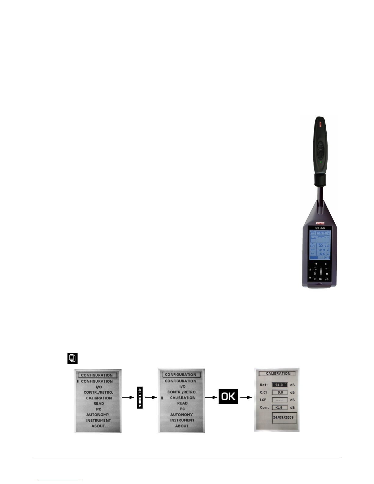
➢ Press key then select CALIBRATION with scrolling knob key and press OK to validate.
Directions for use and sound level meter maintenance 26
Page 27
A new screen is displayed :
➢ Check that the reference value Ref : corresponds to that of the used calibrator and the value
free-field correction C.Cl (0,0 dB for the sound level meter).
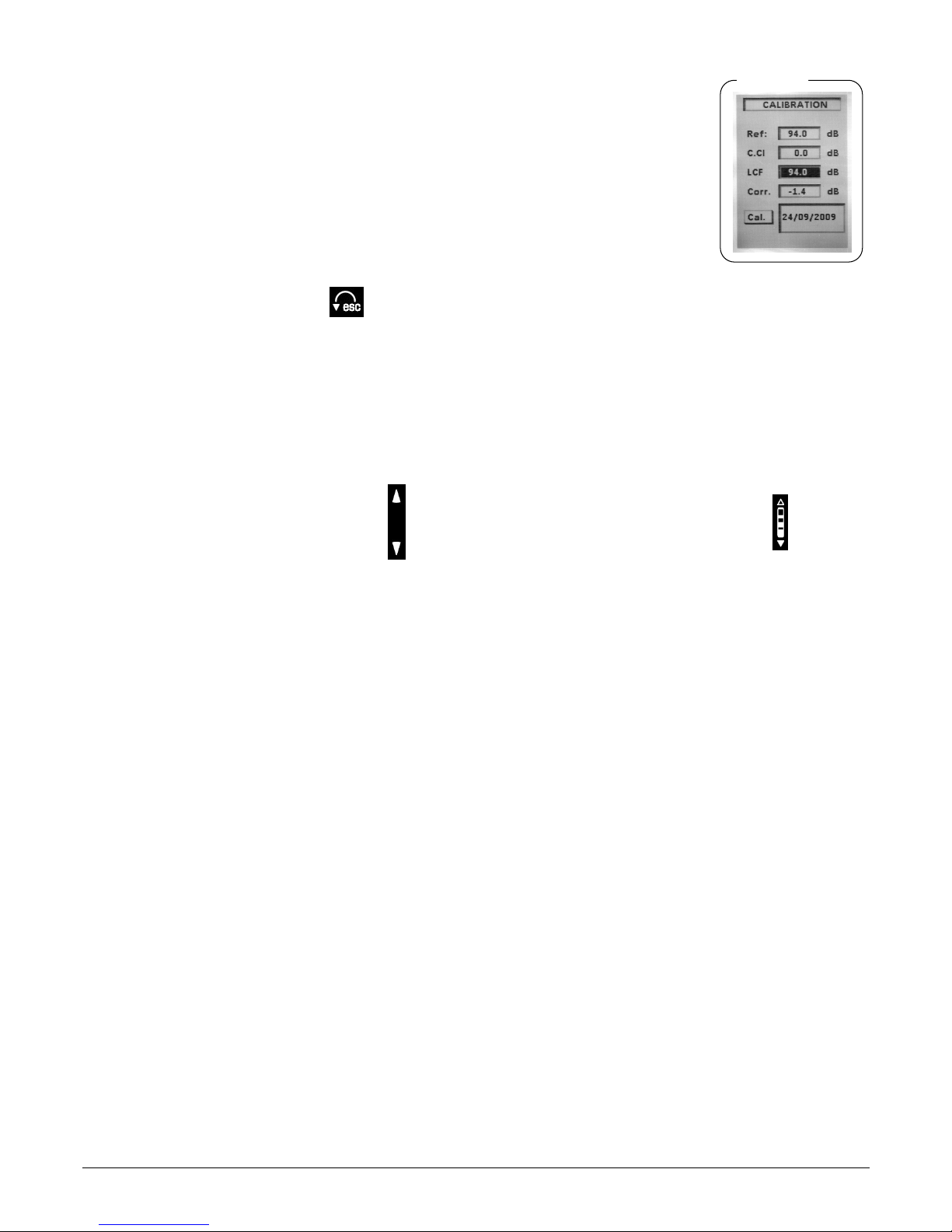
➢ Place the running calibrator on the microphone.
➢ Move the cursor with arrow keys on LCF.
The instrument automatically adjusts the gain of the channel to obtain the coincidence of the levels
displayed in Ref and LCF.
➢ When measurement is stabilized, a pictogram Cal. appears to validate through OK key.
At this moment the correction value of the gain and calibration date are memorized and visible for the
next calibration.
➢ Quit calibration function par with key .
Note : This correction can not exceed +/- 2 dB. If the correction exceeds +/- 2 dB, the coincidence values in Ref and LCF is not
obtained. Reasons of this difference shall be identified (defective microphone, level value of the calibrator not adapted...).
Modification of the reference value
The reference preset value during manufacturing process shows that we use calibrator with rated value of 94 dB at 1000 Hz.
If the proposed reference is not the one of the available calibrator, follow the instruction below :
➢ Move the cursor on Ref. With arrow keys . Adjust to the desired value dB per dB with scrolling knob key .
This new value is memorized until the next change.
9.4 Maintenance
The sound level meter conception allows a reduced maintenance which consists in changing batteries and cleaning the instrument with
a slightly cloth. A particular attention must be paid to the microphone sensor, which is the element the most sensitive of the
metrological chain.
9.5 Regular checking
Like most measuring instruments, it is strongly recommended to regularly control and calibrate DB200 instrument. Return to the
manufacturer each year will provide necessary metrological traceability.
9.6 Change batteries
➢ Turn off the sound level meter.
➢ Return the instrument.
➢ Open the back hatch.
➢ Keep off the 3 batteries and insert the 3 new batteries of type 1.5 V / AAA-LR3 inside. Respect meaning of batteries.
➢ Close the back hatch.
9.7 Replace the batteries with a battery pack
According to the frequency of use of the instrument, it is sometimes better to replace batteries power by a rechargeable Li-ion battery.
The battery life increases to nearly 30 hours of continuous operation.
➢ Turn off the sound level meter.
➢ Remove the battery pack located inside the housing and disconnect the associated connector.
➢ Connect the battery respecting its insertion direction (mechanical keying of security).
27 Directions for use and sound level meter maintenance
Calibration
Page 28

➢ Slide the battery into the housing.
➢ Close the back hatch
9.8 Load the battery
Use a USB power adaptor which serves as a charger.
It's also possible to connect the sound level meter to USB port of a running computer. Battery will load according available current at
the USB output, about 500 mA.
A time of about 8 to 10 hours is needed to obtain a full charge.
Meaning of warning light located next to USB port :
• Red warning light : ongoing load
• Green warning light : completed load
• Blinking red /green warning light : battery is disconnected, check the connection or contact customer support
• Orange warning light after a load period : load or battery trouble : disconnect then connect again the charger. Red warning
light must be turned on to finish loading. If orange warning light appears, contact customer support.
9.9 AC adapter
For measurements over long periods, if possible, use the AC adapter supplied with the instrument. Battery pack (or optional battery)
must stay inside the instrument in order to preserve measurement in case sudden failure of the sector.
Directions for use and sound level meter maintenance 28
Page 29
10 Running informations
10.1 Over-range
Under conditions of measuring range excess, defined at 133,5 dB, Z peak, an over-range icon appears. Its displaying
differs with the measuring mode selected:
• L and L-St modes :
- LXY : it comes fleetingly for each passing. It stays visible at least 1s for a better readability.
- LXpk : warning light appears during the first overload of the input stage, it stays visible during all the measurement.
- LXY max and LXY min : the presence of the warning light indicates that displayed minimum and maximum values have been
overloaded.
Deletion of overload warning lights takes place during a controlled reset by keyboard.
• L-Leq mode :
- LXY : it comes fleetingly for each passing. It stays visible at least 1s for a better readability.
- LXpk et Leq : warning light appears during the first overload of the input stage, it stays visible until the end of the measurement. (24H
maximum)
• Leq-St Mode :
- Leq 0,5s : warning light appears for each overload of input stage, it stays visible during the integration time of 0,5s, then switches off
and so on...
- Leq, DI and LXpk : both warning lights appear for each input stage, they stay visible during the integration time (from 1s to 60s), then
switch off and so on...
- Leq, T : warning light appears during the first overload of the input stage, it stays visible until the end of the measurement.
• S1+S2 mode :
- warning light appears at the first overload of input stage for each measurement, it stays visible until the end of the measurement.
• % of presence of overloads of the input stage :
This information can be required during a mid and long term measurement, when overload indicator is displayed. Its presence does not
provide information about the frequency of occurrence of the overload but the percentage calculation provides a level of alert about
measured and displayed levels by the instrument.
Note : A LXY minimum value may have been overloaded, for example a level of 110 dBA with a high peak factor, while a LXY
maximum value of 125dBA with a low peak factor can not be overloaded.
10.2 Power
When the instrument is equipped with alkaline batteries or with a battery, a symbol informs the user about the remaining
power. In case of low power, less than one bar on the pictogram, the pictogram starts blinking, the instrument stops the
measurement, saves the results and switches off.
During a mains connection for long term measurements, the pictogram automatically changes to represent a plug.
29 Running informations
In case of sudden failure of the sector, the measurement is not saved. To
avoid this trouble, let the batteries or the rechargeable battery inside the
instrument.
Page 30
11 Technical features
11.1 Microphone
The instrument is equipped with an electret microphone with an integrated preamplifier of standardized diameter of ½ inch. Fixed at
the top of the sound level meter, it gives to the group (microphone and housing) free field features compatible with standards.
11.1.1 Sheet
• Marque : KIMO
• Type : Prepolarized free-field ½''
• Grig diameter: 13.2 mm
• Preamplifier : integrated
• Power : 15 V DC
• Nominale sensitivity for preamplifier output : 50mV/Pa
• Equivalent capacity : about 10pF
11.1.2 Frequency response type – reference direction of the sound level meter
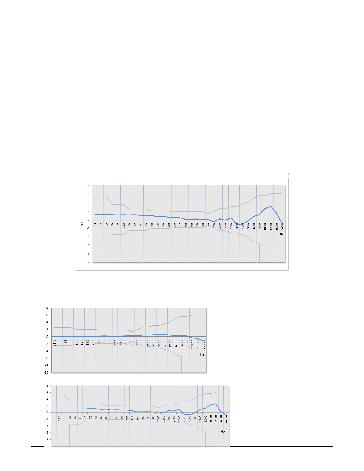
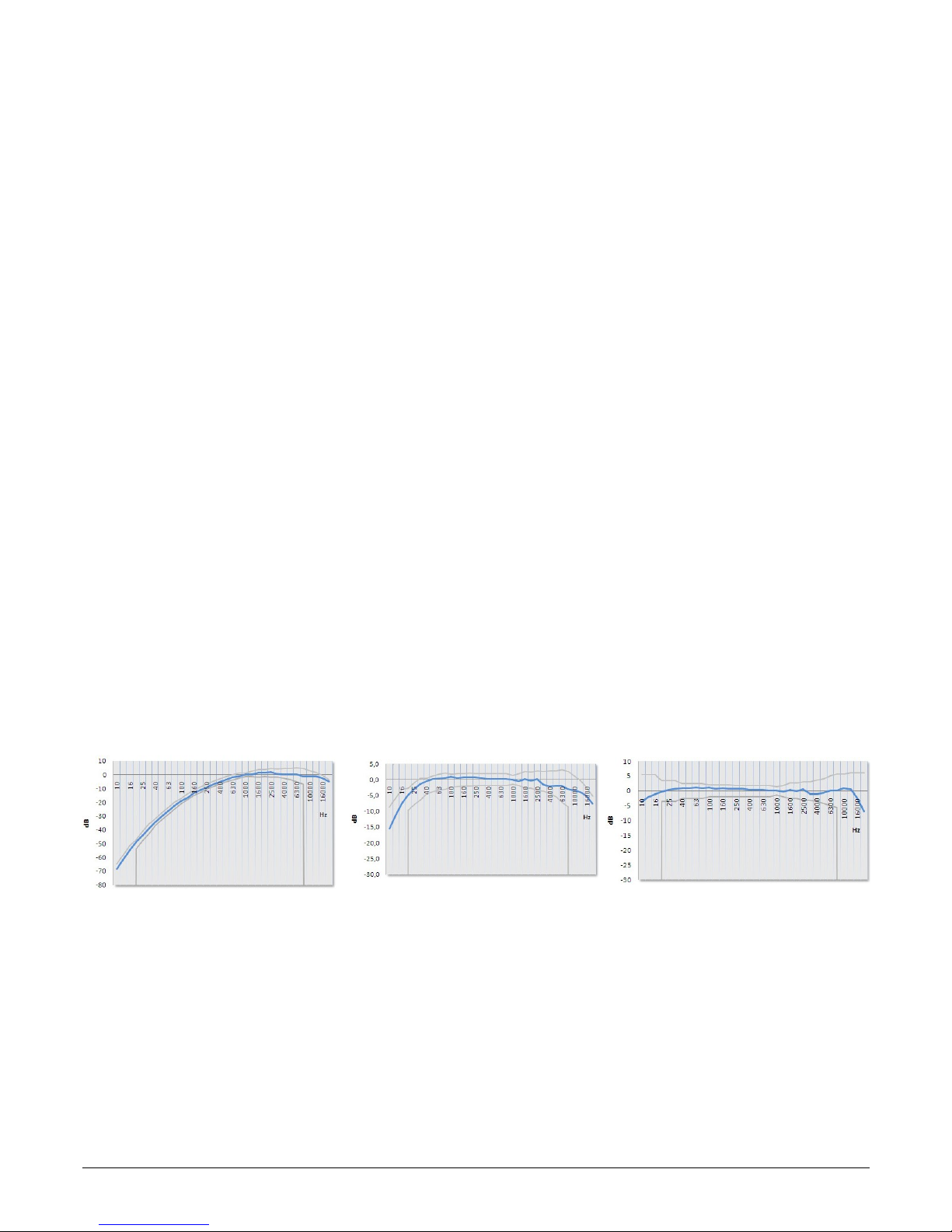
11.2 Windscreen
B-DB23 windscreen creates modifications of free field response that comes in addition to initial features of the microphone on the
housing. The whole stays compliant to requirements class 2 reference standard. So, when using the windscreen, there is no need to
take into account a correction term free field.
Technical features 30
B-DB23 free field response –
template class 2 NF EN 61672-1
Free field response microphone type +
B-DB23 – template class 2 EN NF 61672-1
dB
dB
Page 31
11.3 Measured and displayed values
• A, C or Z- weighted frequency acoustic pressure level and temporally weighted according time weightings : Slow, Fast or
Impulse. E.g. : LAF.
• A, C or Z- weighted frequency maximum acoustic pressure level and temporally weighted according time weightings : Slow,
Fast or Impulse on a measurement time. E.g. : LAFMax
• A, C or Z- weighted frequency minimum acoustic pressure level and temporally weighted according time weightings : Slow,
Fast or Impulse on a measurement time. Ex : LAFmin
• C or Z weighted frequency peak pressure level. Ex : LCpK
• Equivalent continuous level of acoustic pressure, A, C or Z weighted frequency on a T time measurement.
Ex : LAeq,T ou LAT
• Equivalent continuous level of acoustic pressure, A, C or Z frequency weighted on a DI elementary measurement time. Ex :
LAeq,DI
• Equivalent continuous maximum level of acoustic pressure, A, C or Z frequency weighted on DI elementary measurement
time met on the total measurement Ex : LAeq,M
• Equivalent continuous minimum level of acoustic pressure, A, C or Z frequency weighted on DI elementary measurement time
met on the total measurement Ex : LAeq,m
• Level of sound exposure A, C or Z frequency weighted on a T time measurement related to reference time of 1s. Ex : LAE
Statistical indices :
Definition : When the sound level fluctuates, the distribution of the measured levels can be characterized by statistical indices. These
are statistically calculated from the time evolution of the sound level measured in-site. These levels correspond to X-weighted acoustic
pressure level which is exceeded for N% of the time interval. It is noted LN.
Therefore, the statistical indice L1 corresponds to sound level exceeded for 1% of the observation time, L50 for 50% of the time.
Calculated indices are : L01 – L10 – L50 – L90 – L95
11.4 A – C – Z weightings and free field response
The frequency response of the whole microphone / windscreen / A, C or Z weightings (sound level meter) is in compliance with
standards in a given template according the accuracy class of the instrument : NF EN 61672-1 / class 2.
Plots types of free field sound level meter are given below :
Technical features 31
Free field response
with A weighting
Free field response
with C weighting
Free field response
with Z weighting
Page 32

11.5 Metrology
11.5.1 Main features
DB200 sound level meter Classical mode Integrator – averager mode
Electromagnetical compatibility – CE mark As per 89/336/CEE directive and product standards
Standards NF EN 61672-1 (2003)- NF EN 60651
(1994)
NF EN 61672-1 (2003)- NF EN 60804
(2000)
Accuracy class 2
Reference
Pressure level 94dB
Frequency 1000 Hz
Caliber 30-130 dB
Direction 0°: microphone axis
Measuring range
A Weighted 30-130 dB
C Weighted 35-130 dB
Z Weighted 35-130 dB
Peak channel measuring range 83-133 dB
Resolution 0.1 dB
Sound referred to input Compatible with the linear range
Frequency weighting X A – C – Z
Frequency weighting Y Fast (F), Slow(S), Impulse (I)
Overload indicator (min) 133,1 dB
Controlled elementary integration time of
LXeq for storing
1s, 2s, 3s, 5s, 10s, 15s, 30s, 60s
Sampling rate of LXY for storing 1s, 2s, 3s, 5s, 10s, 15s, 30s, 60s
Free integration time – Start/Stop (max)
order
24H00
Statistical indices LXN Calculation based on LXY or LXeq,DI stored data, rounded up to the next dB
on a dynamic of 100 dB
Clock Accuracy Better than 0.01 %
Reference environment 23°C – 50% RH – 1013 hPa
Operating environment From -10°C to +50°C / 650 hPa to 1080 hPa / 25% to 90% FH
Storage temperature From 0°C to +50°C
Dimensions (L x l x e) 270 x 70 x 40 mm
Weight (with batteries) 280 gr
Fixing Fixation on the back of the instrument for tripod
11.6 Plugs and connections
Located under the breastplate in soft rubber, the different plugs and connections stand for :
• Communication with external components : I/O interface
• Battery load (optional) and/or power
• Access micro SD card.
32 Technical features
Page 33

11.6.1 I/O Interface
11.6.2 Transfer plug / load / mains voltage adaptor
This plug is for data transfer, battery load (optional) or power. It's a mini USB format.
• Data transfer : USB mode
• Data Format : proprietary
• Mains supply – charger : type universal USB format – ref : AS-123
PRI : 100V-240V-60/50Hz – 150 mA
SEC : 5V - 1000mA - 5VA
11.7 Memory and storage autonomy
• Memory : micro SD card type, it takes place in the slot on the back of the unit. It allows 25 sessions of 86500 values each.
• Capacity : microSD Card – 1GB or 2GB
Table below shows the measurement time (1 session) according logging time (sampling rate) for LXeq (LXY) storage.
Technical features 33
Access to micro SD card
Not used
Mini USB connector for data transfer –
load battery – mains voltage adaptor
Warning light of the state of
battery charge
I/O 1 : Input : allows
measurement launching
I/O 1 : Output : levels detection
I/O 2 : Input : not used
I/O 2 Output - 0-10V
I/O 1 In - input : start-stop control for measurement :
TTL level maximal 5V – input impedance > 15 kΩ– jack : 2,5 mm diameter
GND : Ground
Measurement
start
Measurement
stop
measurement
I/O 1 Out- output :to activate alarm - maintains high state after detecting a LX or
planned LXeq level . Variable time selected from 1s to 10s by 1s steps.
TTL level 3.3 V – input impedance < 100 Ω - jack : 2,5 mm diameter
I/O 2 Out : DC output : 0-10 Volts – input impedance < 100 Ω - jack : 2,5 mm diameter
dynamic range 0-130dB
step : 0,0769 mV/dB
accuracy : ± 0,3dB
GND : Ground
Not connected
Page 34

Integration time or sampling rate Maximum measurement time (in hours) Maximum measurement time (in days)
1s 24 1
2s 48 2
3s 72 3
5s 120 5
10s 240 10
15s 360 15
30s 720 30
60s 1440 60
11.8 Power and storage autonomy
Measurement autonomies linked to power are given for a running at 20°C and backlight off. Beware of declining capacity of the battery
or batteries for measurement at low temperature.
• Batteries pack : 3 alkaline batteries 1,5V – LR6/AA type
Autonomy (20°C) : 15H in continuous
• Battery : rechargeable Li-Ion type : 3,7 V – 4400 mAh.
Caution : Li-Ion battery is a delicate element. Take care when manipulating or storing.
Autonomy (20°C) : > 24H in continuous
• Mains supply – charger : type universal USB format – ref : AS-123
PRI :100V – 240V - 60/50Hz – 150 mA
SEC : 5V - 1000mA - 5VA
Autonomy : unlimited, depending on memory capacity of the measurement (see table above).
Note : When a connection to a PC for data transfer, the USB computer delivers a voltage of 5V DC 500mA under. This power supply
has priority over the battery pack or battery that is recharged through this power supply.
34 Technical features
In the event of a reset of the memory by the sound level meter or through the
software LDB200, all the memory is erased.
Page 35

12 Packaging and accessories
12.1 Supplied with
The sound level meter is supplied in a transport case with a batteries pack (3 x LR6/AA), a windscreen, a USB cable for transferring
data, a CD-ROM with LDB200 software and user manuals. A calibration certificate is also supplied.
12.2 Optional
• Acoustic calibrator class 2 type : CAL200
• Rechargeable Li-Ion battery and charger – mains adapter USB type : BL-I23
• Mains adapter : AS- 123
• Telescopic tripod : PPCX
• Jacks cables I/O interface : on request
Packaging and accessories 35
Page 36

13 LDB200 software
Supplied with the sound level meter, LDB200 software allows the configuration, data recovery and exploitation stored in the memory of
the instrument.
Easy to use, it requires a smaller learning and allows immediate management of data.
Main functions :
• Visualization and results of the different measurement mode
• Zoom function for more detailed study of a period
• Statistical distribution of data
• Formatting and editing of measurement report.
• Data recovery and creation of text files.
36 LDB200 software
Page 37

Page 38

Page 39

NTang – DB200 – 07/10/10 – RCS (24) Périgueux 349 282 095 Non-contractual document – We reserve the right to modify the characteristics of our products without prior notice.
 Loading...