


Flush-mount transmitter
CPE 300
MODBUS systemMODBUS systemMODBUS system
Remote controlRemote controlRemote control
w
e
N
w
e
N
w
e
N
w
e
N
User Manual
Pressure • Temperature • Humidity • Air Velocity • Air Flow


1. Prerequisite........................................................................................P 1
1.a - ........................................................................
1.b - Output signal selection ..................................................................
Working principle P 1
P 2
2. Modbus parameters ............................................................................P 3
2.a - Configuration parameters ...............................................................P 3
2.b - Modbus functions........................................................................P 3
2.c - Register access security key ...........................................................P 3
3. Access codes to registers....................................................................P 5
4. Display configuration • F100 ..............................................................P 6
4.a - Transmitter channel for infrared remote control .......................................P 6
4.b - Slave addressing (Modbus).............................................................P 6
5. Configuring units of measurement F200 ............................................P 7
6. Analogue output management • F300.................................................P 8
6.a - Output diagnostics.......................................................................P 8
6.b - Analogue output settings ..............................................................P 10
7. Alarm / Relay settings • F400 ...........................................................P 12
7.a - Activation / Deactivation of BEEP alarm..............................................P 12
7.b - Relay security ..........................................................................P 12
7.c - Alarm / relay functions and LED colour codes .......................................P 13
7.d - Alarm mode details.....................................................................P 14
7.e - Alarm mode selection..................................................................P 16
7.f - Setpoinst and time-delay setting.......................................................P 17
8. Pressure measurement configuration • F500.....................................P 19
8.a - Pressure measurement integration ..................................................P 19
8.b - Time-delay between 2 self-calibrations...............................................P 20
9. Other functions .................................................................................P 21
9.a - Activation / Deactivation of the RS232 and home bus ..............................P 21
9.b - Serial number display..................................................................P 21
9.c - Modification of Modbus communication speed ......................................P 22
9.d -Purge mode .............................................................................P 22
10. Error codes .....................................................................................P 24
11. Functions recap...............................................................................P 25
Summary
CPE 300 transmitter configuration via remote control / Modbus

1. Prerequisite
Page 1
1.a - Working principle
Using remote control and optional Modbus configuration, you can change units of measurement, set setpoints and
relays...
Principle: the configuration options are accessed via folders and sub-folders (similar to Windows ). Access is
made via a numerical code (full details in this manual).
®
Visual alarm
LED
Alphanumeric
display
infrared receiver
Meaning of the keys
To increment a value or a level
To decrement a value or a level
To validate an input
To cancel an input or to return to the previous step
Channel selection
With this selector, you can swap the transmission channel so that it
matchs with the transmitter reception channel. See page 6 to configure
the transmitter reception channel.
CPE 300 transmitter configuration via remote control / Modbus

Page 2
1. Prerequisite
The Class 300 can output either a voltage or a current signal.
Voltage or Current ?
Down
4-20 mA
Up
0-10 V
1.b - Output signal selection
With the on-off switch located on the
left top of the transmitter (when
open), you can choose analogue
output 0-10V (voltage) or 4-20
mA (current)
CPE 300 transmitter configuration via remote control / Modbus

• Values formatting - Modbus code : 1440 (channel 1)
1444 (value 1 for the external transmitter)
1448 (value 2 for the external transmitter)
Page 3
2. Modbus parameters
2.a - Configuration parameters
• Communication speed.....................19200 Bauds (see page 22 to configure the speed)
• Data bits.................................8 bits
• Stop bit..................................1 bit
• Parity....................................None
• Flow control.............................None
• Transmitter addressing .................between 1 and 255
default address “0” for single ended bus configuration
To change the addressing, see page 8.
2.b - Functions
• Register reading ...................................Function 03
• Register writing ...............................Function 16
• Communication loop test.....................Function 08
2.c - Access codes to Registers
• Registers type .....................................Signed long integer (32 bits), permuted (LSB, MSB)
• Alarms status - Modbus code : 1436
Relay 1
Relay 2
0101
Ex. The value sent by the transmitter is 5
Alarm condition 1
and relay 1 energized
• Values - Modbus code : 1438 (channel 1)
1442 (value 1 for the external transmitter)
1446 (value 2 for the external transmitter)
Ex. the value sent by the transmitter is 623
...
b4 b3 b2 b1 b0
b31
b31
...
b12 b11 b10 b9 b8 b7
b5 b4 b3 b2 b1 b0
b6
000100001100
Unit of measurement (see chart)
Nr of digits after the comma
Value sign (0=>+, 1=> -)
Ex. The formatting displayed is 268.
Unit of measurement => 12 (see chart)
Figure(s) after the comma => 1
Sign => positive
If the value measured is equal to 623 :
Résultat => 62.3 mmH O
2
Alarm 1
Alarm 2
1 m/s 12 mmH O
2
2 fpm 13 inWg
3 m3/h 14 Kpa
4 L/s 15 mmHg
5 cfm 16 mbar
6 m3/s 17 g/kg
7 °C 18 °C
8 °F 19 °F
9 %RH 20 °C (
10 PSI 21 °F
11 Pa 22 KJ/Kg
(absolute humid.
(dew temp. Td)
(dew temp. Td)
humid temp. Tw)
(humid temp. Tw)
(Enthalpy i)
ñ)
Units of measurement
CPE 300 transmitter configuration via remote control / Modbus

2. Modbus parameters
Page 4
2.c - (sequel)Access codes to Registers
• Serial number of SPI sensing element
Modbus code: 1402
Other access codes to different registers are indicated on each function at stage n°2.
Shown as this pictogram:
d
b
u
o
s
M
200
CPE 300 transmitter configuration via remote control / Modbus

3. Activation code and access to functions
!
This step is COMPULSORY for each configuration.
To access the transmitter functions, and for safety, you have to first enter a safety code.
• Please check that the transmitter is powered on.
• If the transmitter displays an error code, please see “Errors Code” section on page 22
Step 1
Press
to get this screen
Enter the CODE “0101”
with the keypad and
validate with
Step 2
The code must be entered from left to right.
To increment a value or a level, press
To decrement a value or a level, press
To validate a value (level) or to validate the code, press
To return to the previous status or to cancel, press
The first “0” blinks, which means that this column is activated and you can
enter data from the keypad.
This screen appears:
Step 3
This screen confirms that the code was correctly entered, and that you can
configure the transmitter.
If the code was wrongly entered, the transmitter initializes and returns to the
starting display.
N° de dossier de configuration
The transmitter includes 5 folders maximum :
• 100 • 400
• 200 • 500
• 300
Configuration folder
selection
Step 4
To select your configuration folder, press to increment 100 or press to
decrement 100.
Once the folder is selected, press to validate.
L
On the top left of each page of this manual, you can find a reminder of the
configuration folder where the function is available.
F400
Ex. in the folder 400, you
can configure the alarms
and relays. See page 12.
Page 5
CPE 300 transmitter configuration via remote control / Modbus

4. Display configuration
4.a - Transmitter channel for infrared remote control
You can change the channel number for receiving the signal from the infrared remote control.
1
Step
Go into the configuration mode (see page 5). The folder number displayed
corresponds to the last configuration folder used.
2
Step
Select the folder “100” and validate with .
Select the sub-folder “100” and validate with .
The cursor > goes to the line of available choices.
3
Step
With and keys, select the channel number (from 00 to 09). Validate with
.
4
Step
The cursor > returns to sub-folders line.
• press twice to return to reading mode
• press once to select another folder.
• with and keys, you can choose another sub-folder from the folder
d
b
u
o
s
M
200
By default, the channel number is 0.
Page 6
4.b - Slave addressing (Modbus)
Go into configuration mode (see page 5). The folder number displayed
corresponds to the last configuration folder used.
Select the folder “100” and validate with .
Select the sub-folder “103” and validate with .
The cursor > goes to available choices.
With and keys, set the slave addressing number (from 1 to 255).
Validate with .
The cursor > goes to sub-folders line.
• press twice to return to reading mode.
• press once to return to another folder selection.
• with and keys to choose another sub-folder from the folder 100.
d
b
u
o
s
M
206
1
Step
2
Step
3
Step
4
Step
CPE 300 transmitter configuration via remote control / Modbus

5. Configuring channels and units of measurement
Go into configuration mode (see page 5). The folder number displayed
corresponds to the last configuration folder used.
Select the folder “200” and validate with .
The cursor > goes to choices line.
With and keys, select the unit of
measurement (see chart below).
Validate with .
The cursor > returns to sub-folders line.
• press twice to return to reading mode.
• press once to return to another folder selection.
• with and keys to choose another sub-folder from the folder 200.
d
b
u
o
s
M
400
00 Pa
01 mmH O
2
02 inWg
03 mbar
Page 7
1
Step
2
Step
3
Step
4
Step
CPE 300 transmitter configuration via remote control / Modbus

6. Analogue output management
6.a - Output diagnostics
With this function, you can check with a multimeter (or a regulator/display, or a PLC/BMS) if the transmitter outputs
are working properly. The transmitter generates a current (between 4 and 20mA) or a voltage (between 0 and 10V).
6.a.1 - Multimeter connection configuration
Before carrying out the output diagnostics, all connections and configurations of the transmitter must be
enabled, to avoid any damage on the transmitter and the multimeter !
Example of
connection
On the photo alongside, the multimeter is
connected to the 0-10 V output.
Page 8
Power supply
a
Analogue
output
d
Relays
terminal blocks
b
RS 232 connectors
LCC 300 software
e
Pressure
connection
c
CPE 300 transmitter configuration via remote control / Modbus

6.a.2 - Output diagnostics
Once the connection of the transmitter to the multimeter (or regulator or PLC/BMS is complete, (see page
8), you can carry out the analogue output diagnostics on several check points.
6. Analogue output management
Go into configuration mode (see page 5). The folder number displayed
corresponds to the last configuration folder used.
Select the folder “300” and validate twice with .
The cursor > goes to available choices.
Diagnostic Output
00 0 V
01 5 V
02 10 V
03 4 mA
04 12 mA
05 20 mA
With and keys, select the signal that the transmitter must output (see chart
below). Note : no need to validate with .
!
If the deviations are too large (>0,05V or >0,05mA) between the signal issued and the
value displayed on the multimeter, we recommend that you return the transmitter to
our factory.
The cursor > returns to sub-folders line.
• press twice to return to reading mode.
• press once to return to another folder selection.
• with and keys to choose another sub-folder from the folder 300.
Page 9
d
b
u
o
s
M
600
1
Step
2
Step
3
Step
4
Step
CPE 300 transmitter configuration via remote control / Modbus

6. Analogue output management
6.b - Analogue output settings
With this function, you can modify the measuring range of the transmitter, and you can equate the new limits to the
analogue output (0-10V or 4-20mA).
You can enter the measuring range required on your own !
Entrer en mode configuration (cf. page 5). Le numéro de dossier affiché
correspond au dernier dossier de configuration utilisé.
Select the folder “300” and validate with .
Minimum of output
Select sub-folder “301” and validate with .
The cursor > returns to the input line.
With and keys, select the minimum limit value and validate with .
Note : in the left column, you can have either a integer (from 0 to 9) or a
negative sign for a negative minimum limit.
Etape
!
You must enter the values according to the units of measurement selected, not
according to the measuring range of the transmitter.
Ex. on a CPE 303 pressure transmitter (0 to ±1000 Pa) with a reading in mmH2O, the minimum and maximum ranges must
be configured on measuring range of 0 to ±102 mmH2O. See conversion chart on following page.
6
Step
The cursor > goes to sub-folders line.
• press twice to return to reading mode.
• press once to return to another folder selection.
• with and keys you can choose another sub-folder from the folder 300.
After an analogue output setting, if the unit of measurement is modified (see page 5), you have to reconfigure the
outputs according to the new unit of measurement.
!
Nous préconisons un delta entre le minimum et le maximum > 5% de l’étendue de mesure
d
b
u
o
s
M
602
Page 10
1
Step
2
Step
3
Step
4
Step
5
Step
Maximum of output
Select sub-folder “302”and validate with .
The cursor > returns to the input line.
With and keys, select the maximum limit value and validate with .
Note : in the left column, you can have either a integer (from 0 to 9) or a
negative sign for a negative maximum limit.
d
b
u
o
s
M
604
CPE 300 transmitter configuration via remote control / Modbus

Pressiure
6.b.1 - Units of measurement conversion chart
6. Analogue output management
Page 11
Pa mmH2O inWg mbar
CPE 301 0 to ±100 0 to ±10,2 1,00
CPE 302 0 to 0 to ,0 0 to ,01 0 to ,00
CPE 303 0 to 1000 0 to 0 to
0 to ±0,40 0 to ±
±500 ±51 ±2 ±5
± 0 to ±102,0 ±4,02 ±10,00
CPE 300 transmitter configuration via remote control / Modbus

7. Alarm / relay settings
7.a - Activation / Deactivation of BEEP alarm
Go into configuration mode (page 5). The folder number displayed corresponds to
the last configuration folder used.
Select the folder “400” and validate with .
Select sub-folder “400” and validate with .
The cursor > goes to available choices.
With and keys, select 01 to activate the BEEP alarm or 00 to
deactivate. Validate with .
The cursor > goes to sub-folders line.
• press twice to return to reading mode.
• press once to return to another folder selection.
• with and keys you can choose another sub-folder from the folder 400.
7.b - Relay security
Enter in configuration mode (see page 5). The folder number displayed
corresponds to the last configuration folder used.
Select folder “400” and validate with .
Select sub-folder “401” and validate with .
The cursor > goes to available choices.
With the keys and , select 01 for a positive security or 00 for a
negative security. Validate with .
The cursor > returns to sub-folders line.
• press twice on to return to reading mode.
• press once on to return to another folder selection.
• with and keys, you can choose another sub-folder from the folder 400.
The relay outputs are by default, in negative security: the relay is energized when a set point is reached.With
the remote control, you can swap the relays in positive security : then, the relay is de-energized when a set
point is reached or during a power outage.
The beep alarm (audible alarm) is activated when a set point is reached.
For more details on the setpoint settings, see page 20.
d
b
u
o
s
M
800
d
b
u
o
s
M
802
Page 12
1
Step
2
Step
3
Step
4
Step
1
Step
2
Step
3
Step
4
Step
CPE 300 transmitter configuration via remote control / Modbus

7. Alarm / relay settings
7.c - Alarm / relay functions and LED colour codes
7.c.1 - Visual / audible alarms
Class 300 transmitters have 2 visual / audible alarms located in front of the transmitter, allowing to know the
condition of the setpoints.
Alarm LED colour codes
Green The alarm function is activated and
the set point is not reached
Red The alarm function is activated and
the setpoint is reached
None The alarm function is not activated
The red LED appears when the setpoint is reached,
taking into account the time-delay and the action type
(falling or rising).
See page 17 for more details.
Audible alarm
Once the alarm is activated, an alarm sounds
whilst the setpoint is reached.
The BEEP alarm function must be activated to use the
audible alarm. See page 12.
Page 13
Alarm n°2Alarm n°1
CPE 300 transmitter configuration via remote control / Modbus

7.d - Alarm mode details
7. Alarm / relay settings
7.d.1 - Definitions
Setpoint
The setpoint is a limit which, on being reached and/or exceeded , activates an alarm or energizes a relay (in negative
security, see page 14 for more details).
Time-delay
Once the setpoint is reached and/or exceeded, the time-delay postpones the alarm activation (or relay excitation) for a
short period (in seconds). Once this period is elapsed, and if the setpoint is still exceeded, then the alarm is activated or
the relay is energized (in negative security).
Action type
For alarm activation or relay excitation, you can choose the action type: rising or falling action.
• Rising action: the alarm is activated once the measurement goes over the setpoint
• Falling action: the alarm is activated once the measurement goes below the setpoint
7.d.2 - Available configurations
Seuil 1
Seuil 2
Temps
Measurement
Energized
Not energized
Relay status
Negative security
Energized
Not energized
Relay status
Positive security
<T> <T> <T>
<T>
Alarm set
Time-delay
Setpoint 1 > Setpoint 2
Setpoint 2
Setpoint 1
Time
Measurement
Energized
Not energized
Relay status
Negative security
Energized
Not energized
Relay status
Positive security
<T> <T> <T>
<T>
Alarm set
Time-delay
Setpoint 2 > Setpoint 1
Page 14
Configuration N°1 : 2 setpoints and time-delay activated (Control Mode)
Control mode (or
regulation mode)
=>you can regulate the
measurement within a
range determined by 2
setpoints.
CPE 300 transmitter configuration via remote control / Modbus

7. Alarm / relay settings
Configuration N°2 : 1 setpoint, time-delay and rising action activated
Setpoint 1
Time
Measurement
Energized
Not energized
Relay status
Negative security
Energized
Not energized
Relay status
Positivee security
<T> <T> <T>
<T>
Alarm set
Time-delay
Configuration N°3 : 1 setpoint, time-delay and falling action activated
Setpoint 1
Time
Measurement
Energized
Not energized
Relay status
Negative security
Energized
Not energized
Relay status
Positive security
<T> <T> <T>
<T>
Alarm set
Time-delay
Page 15
CPE 300 transmitter configuration via remote control / Modbus
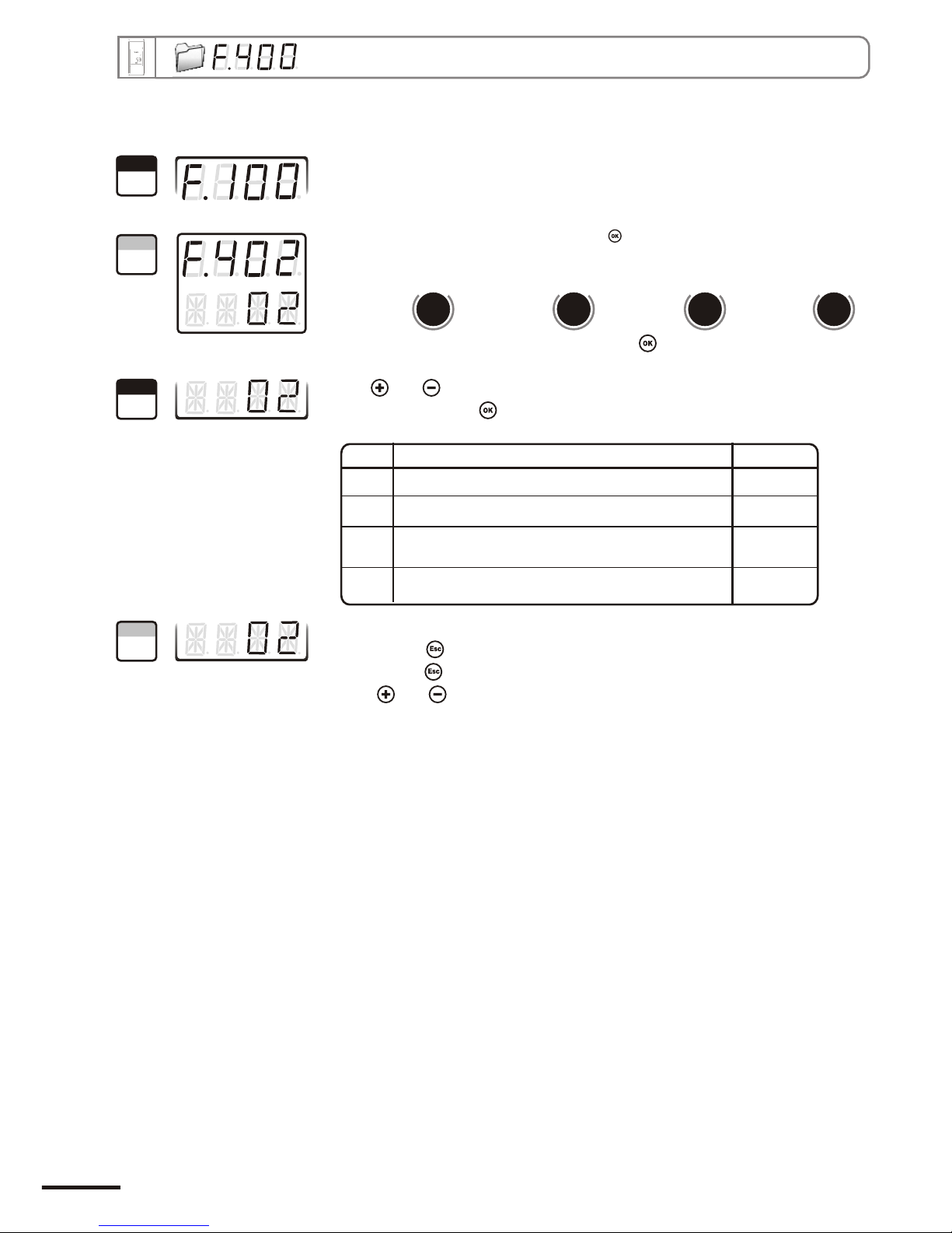
7.e - Alarm mode selection
7. Alarm / relay settings
Go into configuration mode (see page 5). The folder number displayed
corresponds to the last configuration folder used.
Select the folder “400” and validate with .
With and keys, select the code relative to the alarm mode (see chart
below). Validate with .
The cursor > returns to sub-folders line.
• press twice to return to reading mode.
• press once to return to another folder selection.
• with and keys, you can choose another sub-folder from the folder 400.
Code Mode d'alarme Schema
00 No alarm
01 2 setpoints with time-delay (control mode) N° 1 page 14
02 1 setpoint with time-delay and rising action N° 2 page 15
03 1 setpoint with time-delay and falling action N° 3 page 15
1
Step
2
Step
3
Step
4
Step
“402” “406” “410” “414”
Alarm 1 Alarm 2 Relay 1 Relay 2
Select sub-folder
and validate with .
d
b
u
o
s
M
804
d
b
u
o
s
M
812
d
b
u
o
s
M
820
d
b
u
o
s
M
828
Page 16
CPE 300 transmitter configuration via remote control / Modbus

7.f - Setpoints and time-delay setting
7. Alarm / relay settings
Go into configuration mode (see page 5). The folder number displayed
corresponds to the last configuration folder used.
Select the folder “400” and validate with .
With and keys, select the setpoint value and validate with .
Note : the left column can be either a integer (from 0 to 9) or a negative sign
for a negative setpoint.
The cursor > returns to sub-folders line.
• press twice to return to reading mode.
• press once to return to another folder selection.
• with and keys, you can choose another sub-folder from the folder 400.
7.f.1 - Setpoints
!
You must enter values according to the units of measurement selected, not
according to the measuring range of the transmitter.
Ex. on a CP 303 pressure transmitter (0 to ±1000 Pa) with a reading in mmH2O, the minimum and maximum ranges must be
configured on measuring range of 0 to ±102 mmH2O. See conversion chart on page 11.
If after having set up a setpoint, the unit of measurement is modified (see page 9), then you have to reconfigure
the setpoints according to this new unit of measurement.
“403” “407” “411” “415”
Alarm 1 Alarm 2 Relay 1 Relay 2
To configure the setpoint 1, select sub-folder
and validate with .
d
b
u
o
s
M
806
d
b
u
o
s
M
814
d
b
u
o
s
M
822
d
b
u
o
s
M
830
“404” “408” “412” “416”
Alarm 1 Alarm 2 Relay 1 Relay 2
To configure the setpoint 2
b-folder
(alarm in control mode, see p17),
select su
and validate with .
d
b
u
o
s
M
808
d
b
u
o
s
M
816
d
b
u
o
s
M
824
d
b
u
o
s
M
832
1
Step
2
Step
3
Step
4
Step
Page 17
CPE 300 transmitter configuration via remote control / Modbus

7. Alarm / relay settings
Go into configuration mode (see page 5). The folder number displayed
corresponds to the last configuration folder used.
Select the folder “400” and validate with .
Valider avec .With and keys, set the required time-delay: from 00 to
60 seconds. If you do not need the time-delay, enter 00..
Validate with .
The cursor > returns to sub-folders line.
• press twice to return to reading mode.
• press once to return to another folder selection.
• with and keys , you can choose another sub-folder from the folder 400.
7.f.2 - Time-delay
“405” “409” “413” “417”
Alarm 1 Alarm 2 Relay 1 Relay 2
Select sub-folder
and validate with .
d
b
u
o
s
M
810
d
b
u
o
s
M
818
d
b
u
o
s
M
826
d
b
u
o
s
M
834
1
Step
2
Step
3
Step
4
Step
Page 18
CPE 300 transmitter configuration via remote control / Modbus

8. Pressure measurement configuration
8.a - Pressure measurement integration
+/- (
Example : CPE303 (0-1000 Pa) - First measurement: 120 Pa - New measurement : 125 Pa
The pressure source is stable, the user applied a low integration. Integration : 1, maximum variation allowed +/-10 Pa. Since the variation is less than
10 Pa, we apply the integration calculation formula. Next measurement displayed ((9 * 125) + (1 *120 ))/10 = 124.5 soit 124 Pa. If the new value had
been 131 Pa, the next value displayed would have been 100% of the new value, i.e 131 Pa.
The integration coefficient makes an average of the measurements: this helps to avoid any excessive variations
and guarantees a stable measurement.
ew
[((10 - Coef.) x N Value) + (Coef. x former value)]New value displayed = /10
This value is applicable when the variation is less than Coef. x 10 Pa)
Go into configuration mode (see page 5). The folder number displayed
corresponds to the last configuration folder used.
Select the folder “500” and validate with .
Sélectionner le sous-dossier “500” et valider avec .
Le curseur descend sur la ligne des choix possibles.
you can set the integration value: from 00 to 09.
Validate with .
Coefficient 0 : no integration, large variation of the measurement displayed.
Coefficient 9 : maximum integration, more stable measurement display.
d
b
u
o
s
M
1000
The cursor > returns to sub-folders line.
• press twice to return to reading mode.
• press once to return to another folder selection.
• with and keys , you can choose another sub-folder from the folder 500.
1
Step
2
Step
3
Step
4
Step
Page 19
CPE 300 transmitter configuration via remote control / Modbus

8.b - Time-delay between 2 self-calibrations
Go into configuration mode (see page 5). The folder number displayed
corresponds to the last configuration folder used.
Select the folder “500” and validate with .
Select the sub-folder “501” and validate with .
The cursor > goes to available choices.
With and keys, you can set the time-delay values between 2 selfcalibrations: from 0 to 60 minutes. Validate with .
Note : if the value is equal to 0, the transmitter will not carry out any self-calibration
d
b
u
o
s
M
1002
The cursor > returns to sub-folder line.
• press twice to return to reading mode.
• press once to return to another folder selection.
• with and keys , you can choose another sub-folder from the folder 500
Whenever you want, in reading mode, you can carry out a self-calibration by keeping “ESC” pressed
1
Step
2
Step
3
Step
4
Step
Page 20
8. Pressure measurement configuration
CPE 300 transmitter configuration via remote control / Modbus

9. Other functions
9.a- Activation / deactivation of the RS232 and home bus
CPE 300 transmitters have one RS232 and one RS 485 digital output (Modbus protocol) - optional.
With the RS 232, you can display 1 or 2 parameters which are measured by other Class 200 and 300 transmitters, or
you can send measurements to be displayed on another Class 300 transmitters.
Go into configuration mode (see page 5). The
folder number displayed corresponds to the last
configuration folder used.
Select the folder “100” and validate with .
Select the sub-folder “101” and validate with .
With and keys, select 00 to receive data from another transmitter (Home
BusRS485 Modbus active) or select 01 to send data via RS 232 (Home Bus
RS485 Modbus inactive) . Validate with
The cursor > returns to sub-folders line.
• press twice to return to reading mode.
• press once to return to another folder selection.
• with and keys, you can choose another sub-folder from the folder 100.
9.b- Serial number display
Go into configuration mode (see page 5). The folder number displayed
corresponds to the last configuration folder used.
Select the folder “100” and validate with .
Select the sub-folder “102”
Le numéro de série de l'appareil est affiché à l'écran (en 2 parties alternées).
Le curseur retourne sur la ligne des sous-dossiers.
• appuyer 2 fois sur pour revenir en mode lecture des valeurs.
• appuyer 1 fois sur pour revenir à la sélection d’un autre dossier.
• utiliser et pour choisir un autre sous-dossier du dossier 100
!
If you set up your transmitter to send measurements to another transmitter via RS 232, then you
will not be able to use the RS 485 digital output anymore (Modbus -
d
b
u
o
s
M
202
d
b
u
o
s
M
204
1
Step
2
Step
3
Step
4
Step
1
Step
2
Step
3
Step
Page 21
CPE 300 transmitter configuration via remote control / Modbus

Page 22
9. Other functions
9.c- Modification of Modbus communication speed
Go into configuration mode (see page 5). The folder number displayed
corresponds to the last configuration folder used.
Select the folder “100” and validate with .
Select the sub-folder “104” and validate with .
The cursor > returns to sub-folders line.
• press twice to return to reading mode.
• press once to return to another folder selection.
• with and keys, you can choose another sub-folder from the folder 100.
d
b
u
o
s
M
208
With and keys, select a communication speed
(see chart below). Validate with .
00 2400 bauds 03 19200 bauds
01 4800 bauds 04 38400 bauds
02 9600 bauds 05 115200 bauds
(speed by default)
1
Step
2
Step
3
Step
4
Step
CPE 300 transmitter configuration via remote control / Modbus
1
Step
2
Step
3
Step
4
Step
9.d- Purge mode
Go into configuration mode (see page 5). The folder number displayed
corresponds to the last configuration folder used.
Select the folder “300” and validate with .
Select the sub-folder “306” and validate with .
The cursor > returns to sub-folders line.
• press twice to return to reading mode.
• press once to return to another folder selection.
• with and keys, choose another sub-folder from the folder 300
d
b
u
o
s
M
612
With and keys, activate (01 ) or deactivate (00 ) the purge
mode. Validate with .
The purge mode enables to freeze the measurement when being displayed, enables to lock the analogue outputs,
and to activate the relay 1, in order to actuate a de-dust system of a air movement conditions.
9.d.1 -Activation / deactivation of Purge Mode

9. Other functions
Go into configuration mode (see page 5). The folder number displayed
corresponds to the last configuration folder displayed.
Select the folder “300” and validate with .
Select the sub-folder “307” and validate with .
The cursor > returns to sub-folders line.
• press twice to return to reading mode.
• press once to return to another folder selection.
• press and to choose another sub-folder from the folder 300
With and keys, enter the value in seconds of the required
working duration of each purge (from 01 to 60). Validate with .
9.d.2 -Working duration of purge mode
d
b
u
o
s
M
614
1
Step
2
Step
3
Step
4
Step
1
Step
2
Step
3
Step
4
Step
Page 23
CPE 300 transmitter configuration via remote control / Modbus
Go into configuration mode (see page 5). The folder number displayed
corresponds to the last configuration folder used.
Select the folder “300” and validate with .
Select the sub-folder “308” and validate with .
The cursor > returns to sub-folders line.
• press twice to return to reading mode.
• press once to return to another folder selection.
• with and , choose another sub-folder from the folder 300.
d
b
u
o
s
M
616
With keys and , enter the value in minutes of the frequency
of each purge (from 01 to 9999). Validate with .
9.d.3 -Frequency

1
Step
2
Step
3
Step
4
Step
Go into configuration mode (see page 5). The folder number displayed
corresponds to the last configuration folder used.
Select the folder “300” and validate with .
Select the sub-folder “309” and validate with .
The cursor > returns to the sub-folders line.
• press twice to return to reading mode.
• press once to return to another folder selection.
• with and keys, choose another sub-folder from the folder 300.
d
b
u
o
s
M
618
With and keys, enter the value in seconds of the time-delay
required (from 00 to 60). Validate with .
Once the purge is finished, time-delay is a time period before the transmitter returns to measurement
mode and before the analogue outputs are reactivated.
9. Other functions
12.d.4 - Time-delay
10. Error codes
Problem :
• Interchangeable Measuring Sensor (SPI element)
not connected
Solution :
• Connect the probe / SPI (see SPI notice)
Page 24
CPE 300 transmitter configuration via remote control / Modbus

11. Functions recap
Code Description Available settings
200 400 Unit of channel 1
d
b
u
o
s
M
xxx
00 Pa
01 mmH O
2
02 inWg
03 mbar
Code Description Available settings
300 0=>0V, 1=>5V, 2=>10V
3=>4mA, 4=>12mA, 5=>20mA
600
602
604
612
614
616
618
Analogue output setting on channel 1
301 Analogue output minimum on channel 1
302 Analogue output maximum on channel 1
306 Activation / Deactivation of purge mode 00 or 01
307 Working time of each purge from 01 to 60 seconds
308 Frequency of each purge from 01 to 9999 minutes
309 Time-delay after purge from 00 to 60 seconds
d
b
u
o
s
M
xxx
Code Description Available settings
500 0 to 91000
1002
Measurement integration from
501 Self-calibration for time-delay from 0 to 60 minutes
d
b
u
o
s
M
xxx
Page 25
Code Description
101
102
103
Available settings
100 Channel n° for IR remote control 0 to 9
Sending data via Rs232 0 or 1
Serial number display
Modbus slave number 1 to 32
104 Modbus communication speed
200
202
204
206
208
d
b
u
o
s
M
xxx
00 2400 bds 02 9600 bds
01 4800 bds 05 115200 bds
04 38400 bds
03 19200 bds
CPE 300 transmitter configuration via remote control / Modbus
255

11. Functions recap
Code Description Available settings
401 Relays security 0 (negative) or 1 (positive)
402 0=>inactive
1=> setpoint 1, setpoint 2 and time-delay
2=>
3=>
403
404
400 Audible alarm 0 or 1
Channel selection for alarm 1
setpoint 1, time-delay and rising action
setpoint 1, time-delay, and falling action
Setpoint 1 of alarm 1
Setpoint 2 of alarm 1
405 Time-delay on alarm 1 from 0 to 60 seconds
406 Channel selection for alarm 2 0=>inactive
1=> setpoint 1, setpoint 2 and time-delay
2=> setpoint 1, time-delay and rising action
3=> setpoint 1, time-delay and falling action
407 Setpoint 1 of alarm 2
408 Setpoint 2 of alarm 2
409 Time-delay on alarm 2 from 0 to 60 seconds
410 Alarm type selection for Relay 1 0=> inactive
1=> setpoint 1, setpoint 2 and time-delay
2=> setpoint 1, time-delay and rising action
3=> setpoint 1, time-delay and falling action
411 Setpoint 1 of Relay 1
412 Setpoint 2 of Relay 1
413 Time-delay on Relay 1 from 0 to 60 seconds
414 Alarm type selection for Relay 2 0=> inactive
1=> setpoint 1, setpoint 2 and time-delay
2=> setpoint 1, time-delay and rising action
3=> setpoint 1, time-delay and falling action
415 Setpoint 1 of Relay 2
416 Setpoint 2 of Relay 2
417 Time-delay on Relay 2 from 0 to 60 seconds
800
802
804
806
808
810
812
814
816
818
820
822
824
826
828
830
832
834
d
b
u
o
s
M
xxx
ALARM 1ALARM 2RELAY 1RELAY 2
Page 26
CPE 300 transmitter configuration via remote control / Modbus

NOTES...
Page 25
CPE 300 transmitter configuration via remote control / Modbus

NOTES...
Page 26
CPE 300 transmitter configuration via remote control / Modbus

Ref. NT ang - CPE300 - 02/07 B
We reserve the right to modify the characteristics of our products without notice.
 Loading...