


50 Years
KIMBERLEY
Established over
www.kimprod.com.au
‘Monaco’
60lt Dual Capacity
Recycling Solution
‘Side’ Mount
All measurements are in millimeters
Minimum Cupboard Dimension:
Side Mount: 550 (h) x 534 (d) x 414 (w) Maximum Width: 418
Min. 550
Min 414 Max 418
Min. 534
PARTS LIST
• Mounting Brackets x 2
• Runner Brackets x 2
• Frame Assembly x 1
• Door Mounting Brackets x 2
• Lid Assembly x 1
• Buckets x 2
ASSEMBLY KIT
• Screws (8g x 17mm button head) x 16
• Screws (M5 x 12mm Roof) x 10
• Star Washers x 4
TOOLS REQUIRED
• Phillips Head Screwdriver
• Drill & 2mm Drill Bit
Figure 1.
Use these Instructions for
‘SIDE’ Mount
Installations only.
All Illustrations are NOT to scale.
TM
Installation Instructions
Please see the other end
of the Instructions for
‘TOP’ Mount Installations.
D/N: SKRB60E-160817
147
489
40
250
40
489
250
147
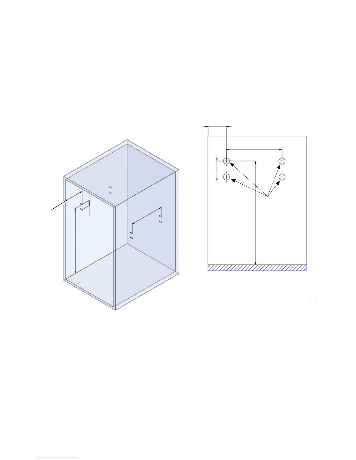
Step 1
Measure & Mark the location of the mounting screws
for the bin, and drill 4 holes in the cupboard as per the
diagram.
Drill Here
Figure 2.
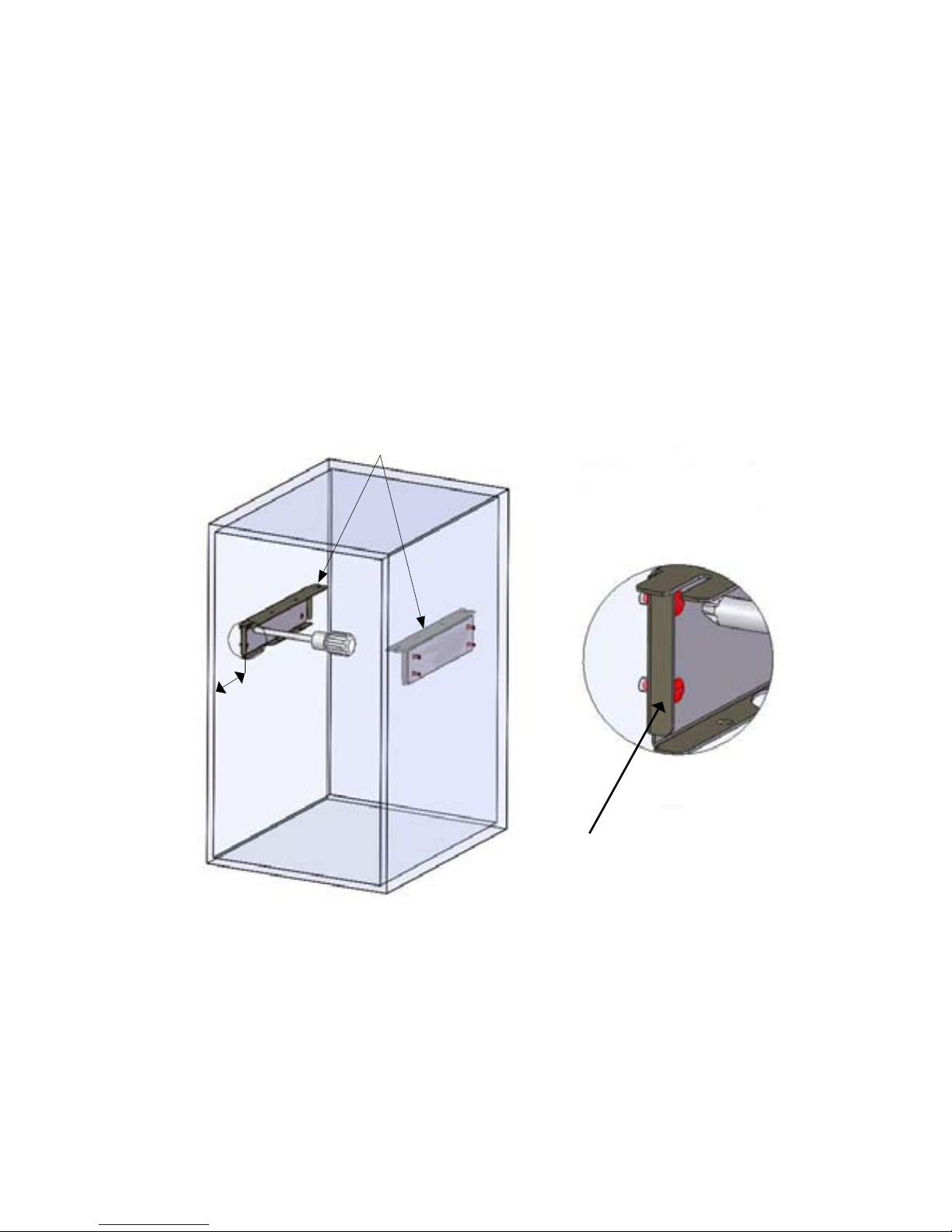
Step 2
Once the Mounting Positions have been accurately
marked & drilled, loosely t the side mounting
brackets into position with 4 screws on the side, as
shown below.
Make sure the distance between the front edge of the
mounting bracket and the edge of the cupboard is
120mm as shown in gure 3.
Then tighten the mounting screws.
120
Detail A
A
Side Mounting Brackets
Figure 3.
Please ensure your measurement
of 120mm is taken from here
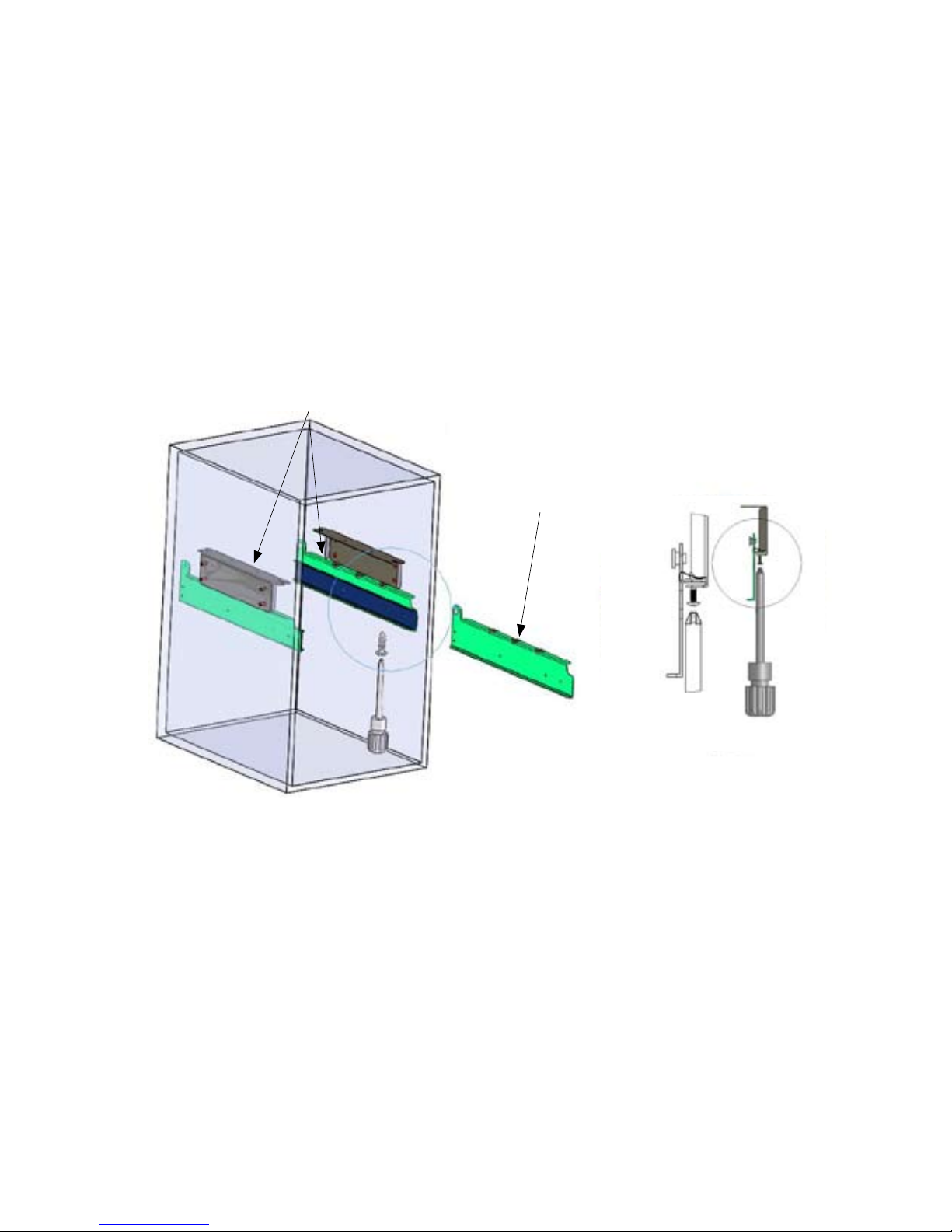
Step 3
Once the side bracket is rmly secured, then t the
drawer runner bracket as shown in gure 4.
See Detail B shows how to assemble the runner
brackets together. Using the 6 screws (M5 x 12mm)
provided, nger tighten, allowing a slight adjustment.
Runner Brackets
Figure 4.
B
Runner Bracket
Detail B
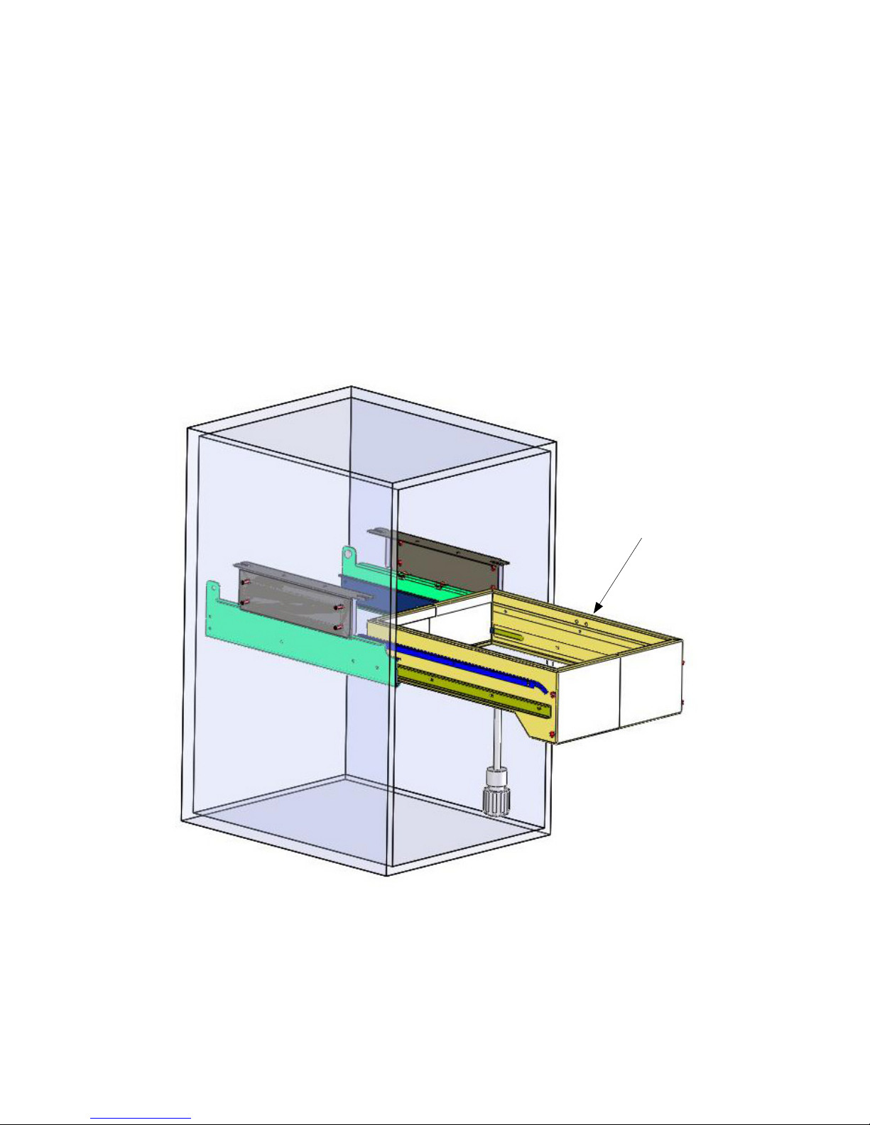
Step 4
Once the runner brackets are installed to the side
mounting bracket, then insert the sliding frame into the
cupboard runners, as shown in gure 5, (Make sure the
runners are located correctly) then slide the frame in &
out, to ensure correct operation. This will help to align
the soft closing damper on the runner.
If this does not operate correctly, then check to see if
the runners are located correctly.
Slider Frame
Once the Slider Frame is moving freely, then the runner
bracket screws can be tightened until secure, as shown
in Detail B on Step 3.
Figure 5.

Step 5
Now the slider has been inserted, check and mark
the height of the screw position on the cupboard
door, as shown in Figure 6. Use 2 screws in each
bracket to x the door into position.
82.50
348
Cupboard Door
Cupboard Door
Template
378
Figure 6.
410
Mark & Drill 4 x 2mm
holes for mounting
bracket.
CAUTION: DO NOT DRILL THROUGH DOOR!
Screws are suited to a
minimum door thickness of 16mm
IMPORTANT:
Please make sure that you allow for the thickness
of this timber when mounting the cupboard door.
Note:
Now the door can be installed on the frame. Small
adjustments can now be made to align door, then
tighten screws.
See Detail D on Step 6 if door alignment needs to be adjusted.
We recommend that 4 more screws can now be installed to
the door brackets for extra support.

Step 6
Once the cupboard door has been installed and
correctly aligned, then insert the lid into the frame
(see Detail C). Finally place both buckets into the
frame, as shown in Figure 7.
C
Detail C
If you have any installation questions,
Please call Kimberley Products Customer Service
on 03 9768 5777 or email kimprod@kimprod.com.au
Figure 7.
D
Door angle
can be
adjusted
Detail D:
Door
E
Front Brackets allow cupboard door angle to be adjusted & squarely aligned,
as shown in Detail D.
E: Shows Door Mounting Bracket, allowing 4 way adjustment.
Detail C:

50 Years
KIMBERLEY
Established over
www.kimprod.com.au
‘Monaco’
60lt Dual Capacity
Recycling Solution
All measurements are in millimeters
Minimum Cupboard Dimension:
Top Mount: 550 (h) x 534 (d) x 418 (w)
PARTS LIST
• Mounting Brackets x 2
• Runner Brackets x 2
• Frame Assembly x 1
• Door Mounting Brackets x 2
• Lid Assembly x 1
• Buckets x 2
ASSEMBLY KIT
• Screws (8g x 17mm button head) x 16
• Screws (M5 x 12mm Roof) x 10
• Star Washers x 4
TOOLS REQUIRED
• Phillips Head Screwdriver
• Drill & 2mm Drill Bit
Min. 550
Min. 418
Min. 534
Figure 1
All Illustrations are NOT to scale.
TM
Use these Instructions for
‘TOP’ Mount
Installations only.
Please see the other end of
the Instructions for
‘SIDE’ Mount Installations.
‘Top’ Mount
Installation Instructions

Step 1
Measure & Mark the location of the mounting screws
for the bin, and drill 4 holes in the cupboard as per the
diagram.
Figure 2.

Step 2
Once the Mounting Positions have been accurately
marked & drilled, loosely t the top mounting brackets
into position with 2 screws in each bracket, as shown
below.
Make sure the distance between the front edge of the
mounting bracket and the edge of the cupboard is
120mm as shown in gure 3.
Fix the remaining screws into position (as shown in
Detail A) ensuring each bracket has been secured with
4 screws.
Then tighten the mounting screws.
Detail A:
Figure 3.
Please ensure your measurement
of 120mm is taken from here

Step 3
Once the top bracket is rmly secured, then t the
drawer runner bracket as shown in gure 4.
Detail B shows how to assemble the runner brackets
together. Using the 6 screws (M5 x 12mm) provided,
nger tighten, allowing a slight adjustment.
B
Detail B:
Runner Bracket
Figure 4.

Step 4
Once the runner brackets are installed to the top
mounting bracket, then insert the sliding frame into the
cupboard runners, as shown in gure 5, (Make sure the
runners are located correctly) then slide the frame in &
out, to ensure correct operation. This will help to align
the soft closing damper on the runner.
If this does not operate correctly, then check to see if
the runners are located correctly.
Once the Slider Frame is moving freely, then the runner
bracket screws can be tightened until secure, as shown
in Detail B on Step 3.
Figure 5.
Slider Frame

Step 5
Now the slider frame has been inserted, check
and mark the height of the screw position on the
cupboard door, as shown in Figure 6. Use 2 screws
in each bracket to x the door into position.
Note:
Now the door can be installed on the frame. Small
adjustments can now be made to align door, then
tighten screws.
See Detail D on Step 6 if door alignment needs to be adjusted.
We recommend that 4 more screws can now be installed to
the door brackets for extra support.
Screws are suited to a
minimum door thickness of 16mm
Mark & Drill 4 x 2mm holes
for mounting bracket.
Figure 6.
IMPORTANT: Please make sure that you allow for the thickness
of this timber when mounting the cupboard door.
CAUTION: DO NOT DRILL THROUGH THE CUPBOARD!
Min. 460

Step 6
Once the cupboard door has been installed and
correctly aligned, then insert the lid into the frame
(see Detail C). Finally place both buckets into the
frame, as shown in Figure 7.
If you have any installation questions,
Please call Kimberley Products Customer Service
on 03 9768 5777 or email kimprod@kimprod.com.au
Figure 7.
C
Detail C:
D
Front Brackets allow cupboard door angle to be adjusted & squarely aligned,
as shown in Detail D.
Door angle
can be
adjusted
Detail D:
Door
E
E: Shows Door Mounting Bracket, allowing 4 way adjustment.
 Loading...