

Kimball President, Senator Assembly & Instruction Manual

President™ and Senator
™
Assembly Instructions
1998762 Revision B-13
Complete Series Master Packet
Proper product installation, in accordance with these instructions, is the responsibility of the installing agent.
If you have any questions concerning these instructions, please call Kimball Office Customer Service.
© 2008 Kimball International, Inc. T 800.482.1818 F 812.482.8300
Casegoods Assembly Instructions
President/Senator
Printed in U.S.A. © 2002 Kimball International, Inc. T 800.482.1818 F 812.482.8300
Proper product installation, in accordance with these instructions, is the responsibility of the installing agent.
If you have any questions concerning these instructions, please call Kimball Office Customer Care.
Part No. 1567892 Revision A-02
Page 1 of 1
Bookcase Cornice Frame
Tools Required
■ Level
■ Ta pe Measure
■ Power Screwdriver
■ #2 Phillips Head Bit
Package Contents
■ 16 #8 x ⁵⁄₈" Panhead Screws
Installation
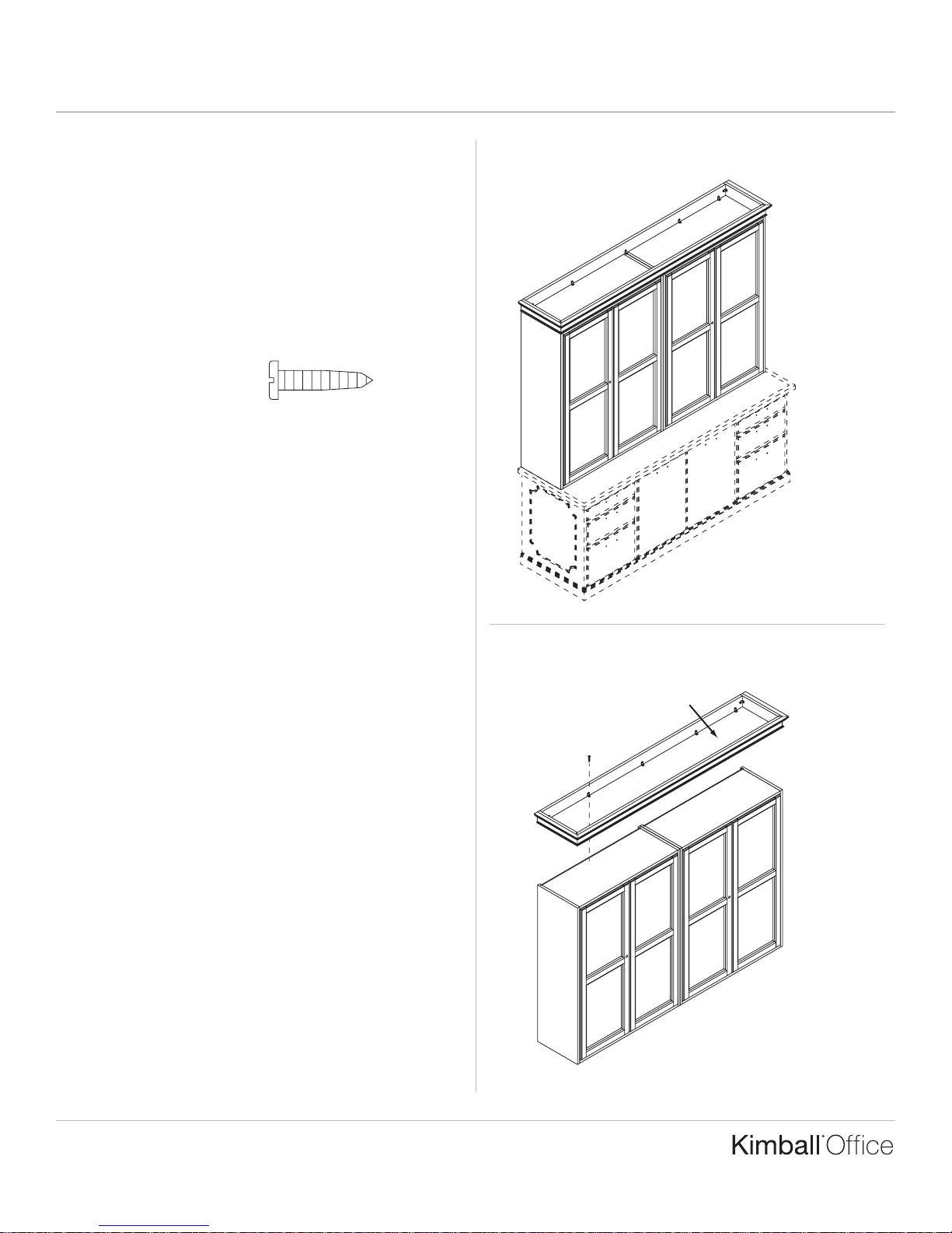
1. The cornice frame can be attached to one, two, or three
bookcase units. Position the lower storage in the desired
location. Level lower storage units. Position bookcase units
onto lower storage in the desired location. (Figure A).
2. Align the cornice above the bookcase units. Attach the
cornice to the bookcase units using the #8 x ⁵⁄₈" screws,
provided. (Figure B).
Figure A
Figure B
Cornice
Casegoods Assembly Instructions
President/Senator
Printed in U.S.A. © 2002 Kimball International, Inc. T 800.482.1818 F 812.482.8300
Proper product installation, in accordance with these instructions, is the responsibility of the installing agent.
If you have any questions concerning these instructions, please call Kimball Office Customer Care.
Part No. 1567893 Revision A-02
Page 1 of 1
Bookcase Top Panel
Tools Required
■ Level
■ Ta pe Measure
■ Power Screwdriver
■ #2 Phillips Head Bit
■ ³⁄₁₆" Drill Bit
Package Contents
■ 16 #8 x 1¹⁄₂" Screws
Installation
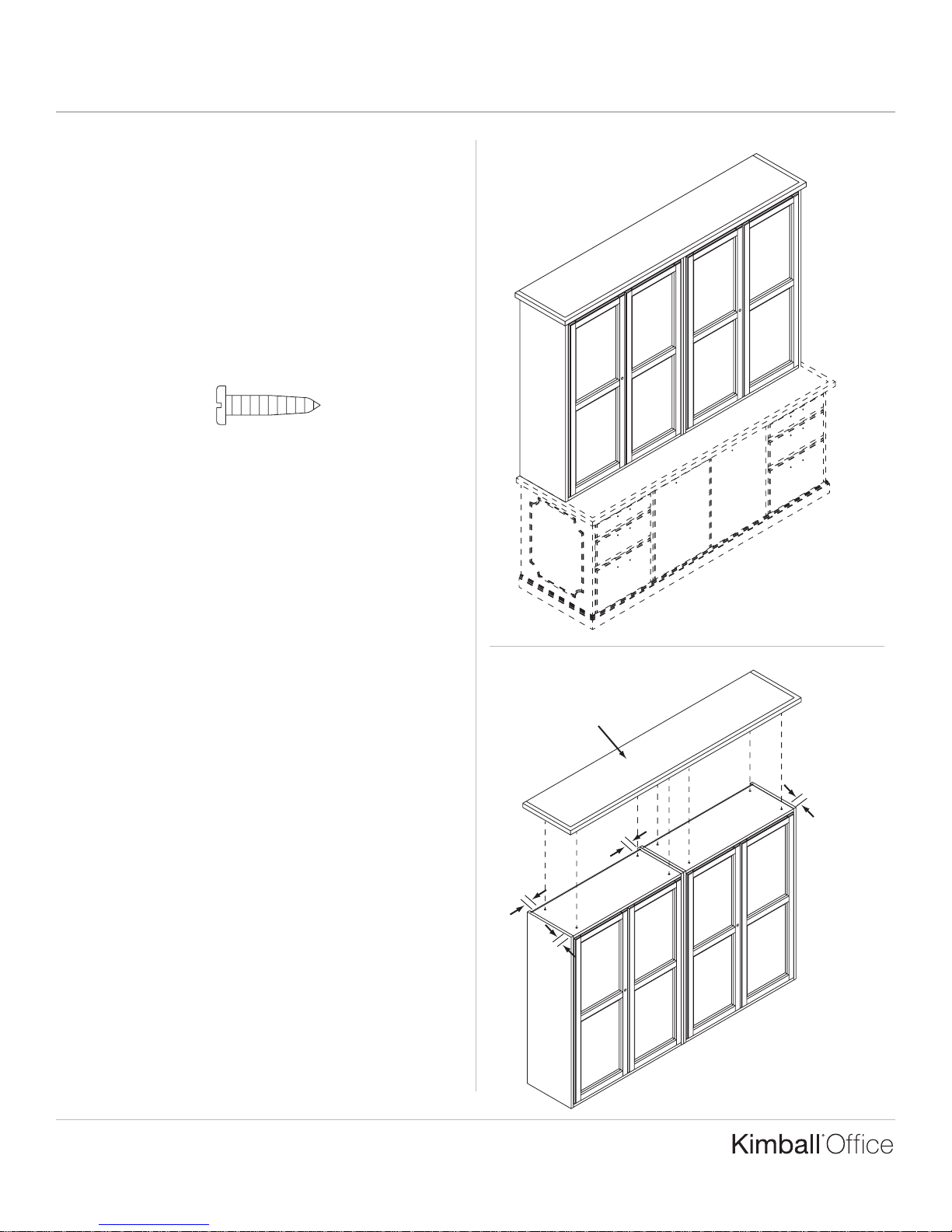
1. The top panel can be attached to one, two, or three
bookcase units. Position the lower storage in the desired
location. Level lower storage units. Position bookcase
units onto lower storage in the desired location. Level all
bookcase units. (Figure A).
2. Bore four ³⁄₁₆" diameter holes approximately 2" in from the
front, back and sides of each vertical storage unit. Position
the top panel in the desired position on the bookcase units
and attach from inside bookcase using provided
#8 x 1¹⁄₂" screws. (Figure B).
Top Panel
2"
2"
2"
2"
Figure B
Figure A
Casegoods Assembly Instructions
President/Senator/Innsbruck/Osterley Park
Proper product installation, in accordance with these instructions, is the responsibility of the installing agent.
If you have any questions concerning these instructions, please call Kimball Office Customer Care.
Part No. 1741515 Revision A-04
Page 1 of 2
Ta ble Desk
Tools Required
■ Level ■ ³⁄₄" Socket
■ Socket Wrench
Package Contents
■ 1 Table Desk ■ 4 Table Leg with Lag Bolt,
Washer, Lock Washer and Nut
Installation
Note: This instruction shows the President Table Desk
assembly as an example. This instruction can also be
applied to Senator and Innsbruck/Osterley Park Table
Desk assembly. For safety, and to avoid damage to the unit,
it is recommended that more than one person be used to
assemble and move the Table Desk.
1. The table desk will arrive unassembled with the legs
located on the underneath side of the worksurface.
Carefully un-carton and place worksurface face down on
a smooth, clean, soft surface. (Figure A).
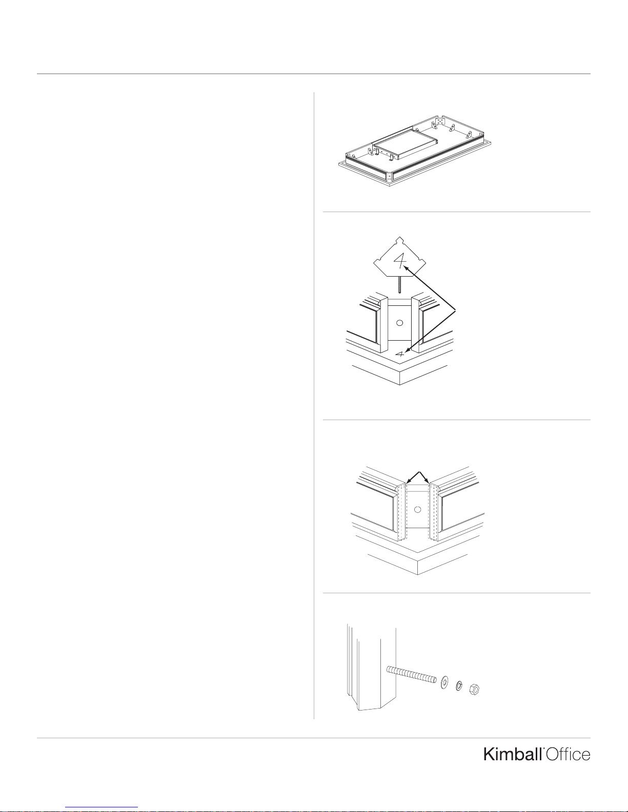
2. Remove the table legs from the underside of the
worksurface and remove all foam packing. Legs are
numbered 1, 2, 3, and 4 on their top ends to correspond
with their appropriate corner location, which is numbered
on the underside of the worksurface. (Figure B).
3. During production, a wooden spacer is fastened to the
apron rail where the legs attach. Normally, they are removed
before shipment. However, if any spacers remain on the
apron rail please remove and discard all of them as they
will interfere with installation of the table legs. (Figure C).
4. Locate the table leg numbered “1” and remove the nut,
lock washer, and washer from the lag bolt. (Figure D).
Figure A
Figure B
Top o f l eg is numbered to
match with number on
underside of worksurface
Figure C
Figure D
Remove any and
all spacers from
apron rail
Remove all hardware
from lag bolt
Casegoods Assembly Instructions
President/Senator/Innsbruck/Osterley Park
Printed in U.S.A. © 2004 Kimball International, Inc. T 800.482.1818 F 812.482.8300
Proper product installation, in accordance with these instructions, is the responsibility of the installing agent.
If you have any questions concerning these instructions, please call Kimball Office Customer Care.
Part No. 1741515 Revision A-04
Page 2 of 2
Installation (continued)
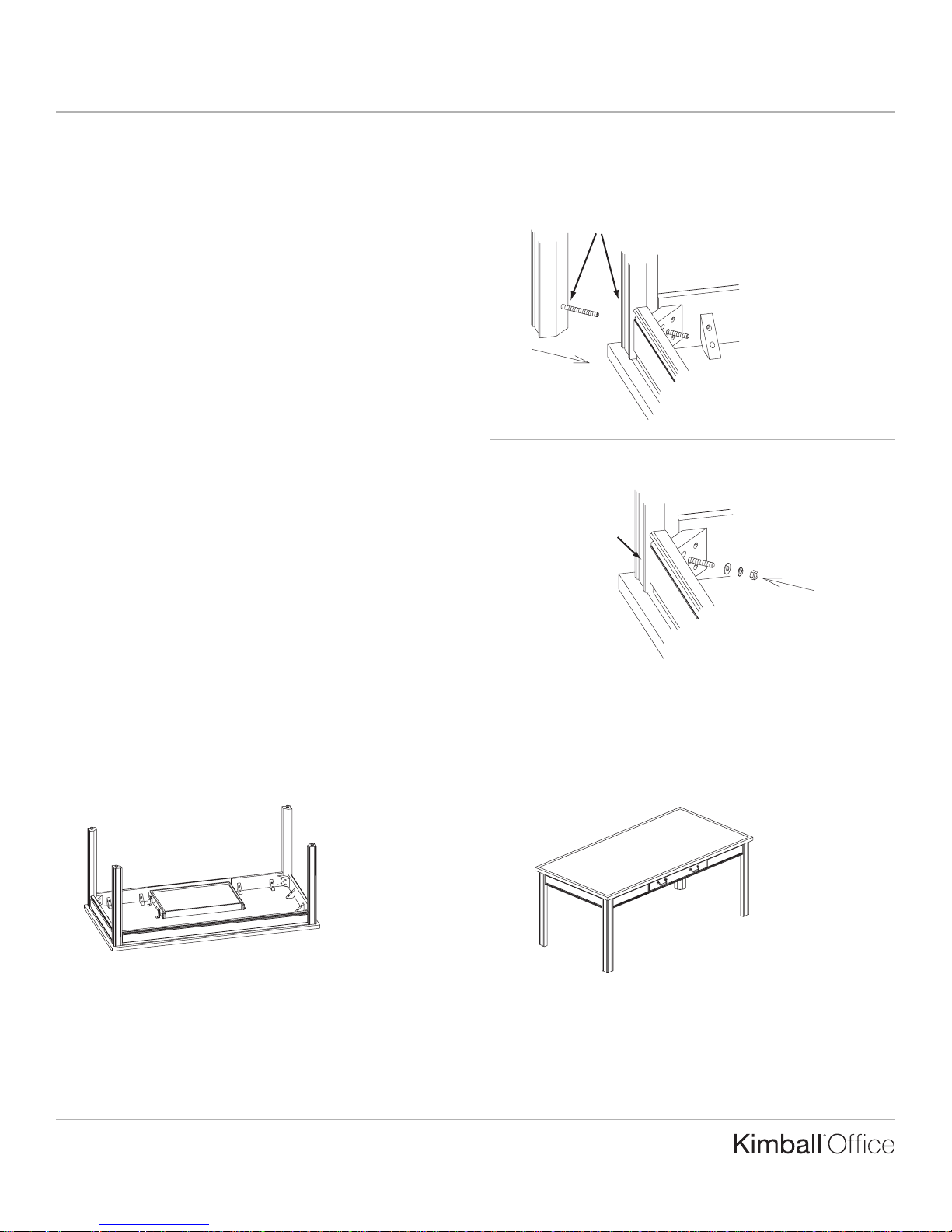
5. Insert the lag bolt through the hole in the corner block at
the corner numbered “1” on the worksurface. (Figure E).
6. Secure the leg to the table by installing the hardware in the
following order: washer, lock washer, nut – to the outside of
the corner block. Make sure the leg is perpendicular and
flush to the apron rails. Tighten the nut firmly by using the
³⁄₄" socket wrench, but do not over-tighten. (Figure F).
7. Refer to Steps 4, 5, and 6 to install legs “2”, “3”, and “4” to
their corresponding locations. (Figure G).
8. After all legs are installed, carefully turn table to the upright
position. If the table displays a swaying motion, then one or
more of the legs are not properly seated in their locations.
Tu rn the table back over on the soft surface and re-check all
legs to make sure they are perpendicular and flush to the
apron rails and that all fasteners are properly installed and
tightened. (Figure H).
Figure E
Figure F
Figure G
Figure H
Make sure number
on leg and on the
worksurface are
the same
Install hardware
in this order
Perpendicular
and flush against
apron rails
Insert Lag Bolt
through
Corner Block
Casegoods Assembly Instructions
President/Senator
Proper product installation, in accordance with these instructions, is the responsibility of the installing agent.
If you have any questions concerning these instructions, please call Kimball Office Customer Care.
Part No. 1741516 Revision A-04
Page 1 of 2
Ta sk/Reception Station
Tools Required
■ Level ■ #2 Phillips Head Bit
■ Ta pe Measure ■ ³⁄₁₆" Drill Bit
■ Cordless Drill
Package Contents
■ 2 Flat Brackets ■ 2 Flat Brackets
(attach worksurfaces) (attach modesty panels)
■ 32 #10 x 1" Panhead Screws ■ 32 #8 x ⁵⁄₈" Panhead Screws
(worksurfaces) (modesty panels)
■ Foam tape (light blocker)
Installation
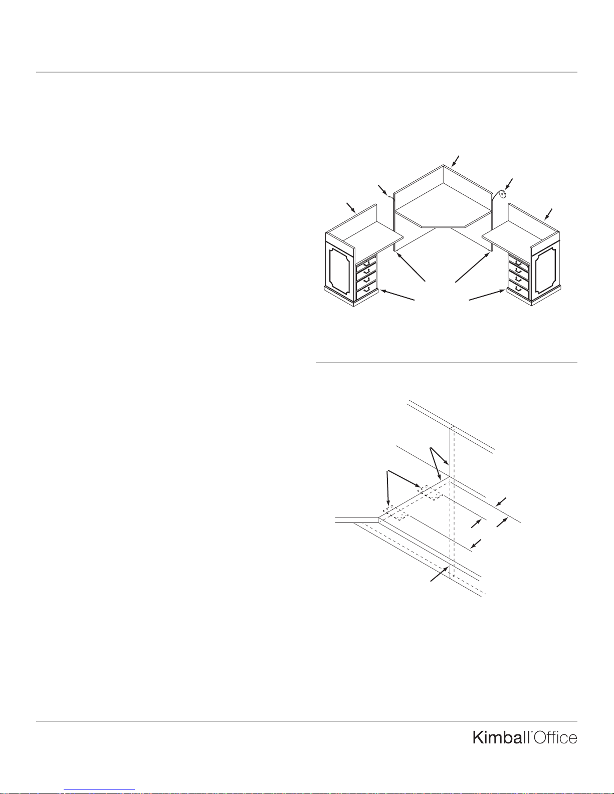
1. Task/Reception Stations are comprised of a Corner Unit,
one Left Return, and one Right Return. These units will not
stand alone, nor attach to other units in the series. Position
the units in their approximate desired location. (Figure A).
2. Unroll the foam tape and apply a single strip of tape, gray
side down, to the center of the exposed ends of the Corner
Unit. Remove the protective film from the exposed side of
each piece of tape. The foam tape is used as a light blocker
when panels are installed next to each other. (Figure A).
3. Level all units. Attach two flat brackets to the underside of
the worksurface on the Corner Unit on each side at the
locations shown in Figure B, using the provided #10 x 1"
Panhead Screws. Center the brackets with the edge of the
worksurface.
4. Position the Returns against the Corner Unit. Pull all Units
together so that the Corner and Return Unit worksurfaces
are flush and tight against each other with no gaps.
Note: The worksurfaces can be unscrewed from cleats
and adjusted to align, if necessary.
Align the Corner Unit Modesty Panels and the Return
Modesty Panels so they are flush and tight against each
other with no gaps. This can be done by adjusting the leg
levelers up/down on the Corner and Return Units.
(Figure B).
Figure A
Figure B
Apply Foam Tape
Flush with
no gaps
Peel off
Protective Film
Corner Unit
Right Return
Left Return
Center brackets on
edge of worksurface
Use Levelers
to adjust/align
4"
Flush with
no gaps
19"
Casegoods Assembly Instructions
President/Senator
Printed in U.S.A. © 2004 Kimball International, Inc. T 800.482.1818 F 812.482.8300
Proper product installation, in accordance with these instructions, is the responsibility of the installing agent.
If you have any questions concerning these instructions, please call Kimball Office Customer Care.
Part No. 1741516 Revision A-04
Page 2 of 2
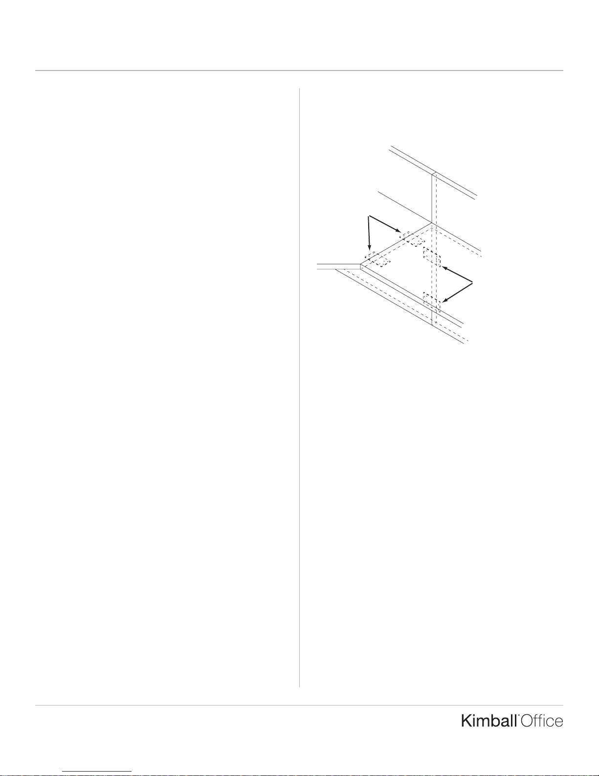
Installation (continued)
5. When all gaps are eliminated, attach the Corner Unit
Modesty Panels to the Return Unit Modesty Panels first
using two flat brackets on each side. Center the brackets
between each Modesty Panel and attach one flat bracket
towards the top of the Modesty Panels under the
worksurface and the other flat bracket towards the bottom
of the Modesty Panels using the provided #8 x ⁵⁄₈" Panhead
Screws. (Figure C). Fasten each Return worksurface to the
Corner Unit flat brackets using the provided #10 x 1"
Panhead Screws. (Figure C).
Note: The worksurface flat brackets are shipped on the
underside of the Return worksurface.
Figure C
Attach Returns
to Flat Brackets
Center Flat Bracket
between Modesty Panels.
Attach Flat Brackets to
Modesty Panels.

Casegoods Assembly Instructions
President/Senator
Proper product installation, in accordance with these instructions, is the responsibility of the installing agent.
If you have any questions concerning these instructions, please call Kimball Office Customer Care.
Part No. 1741518 Revision B-04
Page 1 of 1
Printed in U.S.A. © 2004 Kimball International, Inc. T 800.482.1818 F 812.482.8300
Tr ansaction Shelf
Tools Required
■ #2 Phillips Head Bit ■ Cordless Drill
Package Contents
■ 1 Transaction Shelf ■ 9 #8 x ⁵⁄₈" Panhead Screws
■ 9 Brackets ■ 9 #8 x ³⁄₄" Flathead Screws
Installation
1. The transaction shelf can be used with the task/reception
station. The transaction shelf can be positioned on either
the left or right hand side of the station. The shelf rests
ON TOP of the 43" high panels (not inset). (Figure A).
2. The transaction shelf is fastened to the station using the
provided brackets and screws. The brackets mount flush
with the top edge of the 43" high panels. The front brackets
mount 10" off the inside edge of the station. The back
brackets should be spaced about every 12". Fasten the
brackets to the 43" high panels using the provided #8 x ⁵⁄₈"
panhead screws. (Figure B).
3. Place the transaction shelf on top of the 43" high end
panels. Position the shelf so that it overhangs all edges
equally. Fasten the shelf to the brackets using the provided
#8 x ³⁄₄" flathead screws. (Figure C).
Figure A
Figure C
Attach Brackets
using #8 x ⁵⁄₈"
Panhead Screws
Figure B
Overhang
all edges
equally
12"
10"
12"
Attach top
using #8 x ³⁄₄"
Flathead Screws
 Loading...