

Kimball Fluent Series Assembly Instructions Manual

Fluent®
Assembly Instructions
2112664 Revision A-11
Complete Series Master Packet
Proper product installation, in accordance with these instructions, is the responsibility of the installing agent.
If you have any questions concerning these instructions, please call Kimball Office Customer Service.
© 2011 Kimball International, Inc. T 800.482.1818 F 812.482.8300

Fluent®
Assembly Instructions
1
Leg & Pedestal to Worksurface
Tools Required
• Pencil
• Tape Measure
• Screw Gun
Hardware Required
Leg Assembly
• #10 x 1” Panhead Screw
• Double Sided Adhesive
Installation
Leg Assembly to Worksurface
Note: It is recommended that two (2) persons be used to lift
and flip worksurfaces.
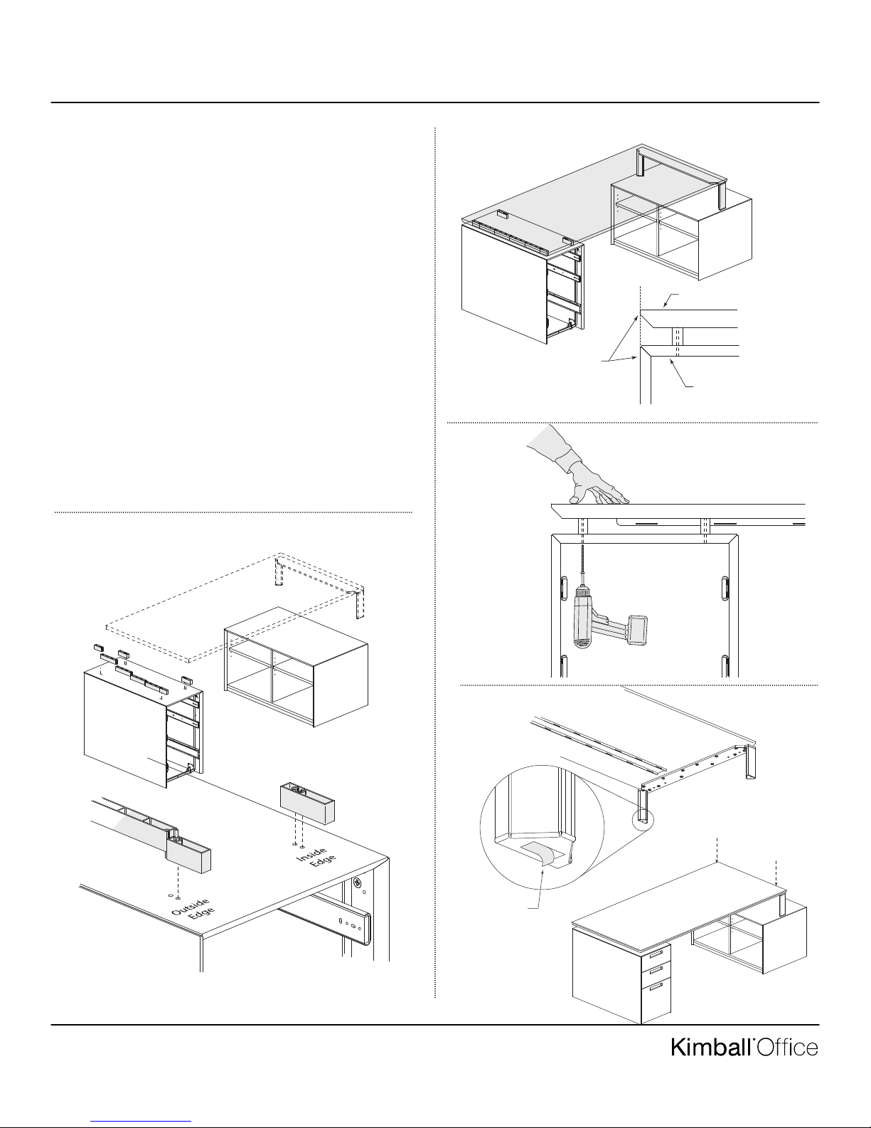
1. Place the worksurface on a clean, soft surface, underside
facing up. Align leg assembly centered front to back and
flush with outside worksurface edge. (Figure A). Drill pilot
holes to insure legs are mounted perpendicular to surface.
Attach legs using fourteen (14) #10 x 1” panhead screws
provided. (Figure B).
2. If using low storage support legs with a low storage unit,
cut two pieces of double-sided adhesive tape and place on
bottom of legs. DO NOT REMOVE film backer exposing
adhesive at this time. (Figure C).
Note: The top surface of the low storage unit MUST be clean,
dry, and free of any dirt or residue to assure adequate adhesion.
Caution: The tape is a very strong adhesive and bonds instantly to any surface it is applied.
• #2 Phillips Head Bit
• 5/32” Drill Bit
Pedestal
• Pedestal Spacer
• #8 x 2 1/2” Flathead
Screw
Figure B
Figure C
Pre-Drill Pilot
Holes Prior to
Fastening
screws.
Double Sided Tape
(Do not remove film
backer at this time)
Figure A
Leg Assembly
Worksurface
Proper product installation, in accordance with these instructions, is the responsibility of the installing agent.
If you have any questions concerning these instructions, please call Kimball Office Customer Care.
Part #2205351, Revision C
Desk-Height
Support Legs
Flush
Low Storage
Support Legs

Fluent®
Installation (continued)
3. If leg resin inserts are to be used, remove leg adjustment
cap from both legs. Slide resin insert into extruded channels of leg assembly and reattach leg caps. (Figure D).
4. He leg assembly wire manager is attached with double
sided adhesive tape. Peal off film backer from tape and
apply wire manager to inside of leg. (Figure E).
Pedestal to Worksurface:
5. Remove all drawers from pedestals. See drawer removal
installation sheet.
6. All pedestals are shipped with eight (8) factory predrilled
pilot holes. Locate these holes on the underside of the pedestal, there are two holes near each of the four corners.
Using a 5/32” drill bit, carefully bore through each hole
perpendicular to the surface. (Figure F).
Figure D
Assembly Instructions
2
Figure E
Wire Manager
Peel off film
backer
Figure F
8 Pilot Holes
Proper product installation, in accordance with these instructions, is the responsibility of the installing agent.
If you have any questions concerning these instructions, please call Kimball Office Customer Care.
Part #2205351, Revision C
Fluent®
Installation (continued)
7. Determine which side of the desk the pedestals will be
located. Interlink the spacers together and align them over
the outside edge holes. Align the two single spacers on
inside edge holes. (Figure G).
8. Flip worksurface with attached leg assembly right side up
and position over the top of pedestal. Centered front to
back and flush with outside edges, carefully lower worksurface onto pedestal as not to move spacers. (Figure H).
9. Verify that holes in pedestal are aligned with holes in spacers, if not adjust accordingly. To fasten pedestal to worksurface, one person must secure worksurface in place
while another inserts six (6) #10 x 2” screws from underside of pedestal. (Figure I).
10. To securely attach low storage support legs to low storage
units, position storage unit centered under support legs.
Slightly lift up on end of worksurface to expose double
sided tape and remove film backer. Lower worksurface
back down onto storage unit and apply direct downward
pressure to adhere the surface. Replace all drawings.
(Figure J).
Assembly Instructions
3
Figure H
Worksurface
Flush
Pedestal
Figure I
Figure G
Figure J
Peel off
film backer
Proper product installation, in accordance with these instructions, is the responsibility of the installing agent.
If you have any questions concerning these instructions, please call Kimball Office Customer Care.
Part #2205351, Revision C
Fluent
Assembly Instructions
age 1 of 2
P
Glass Tables
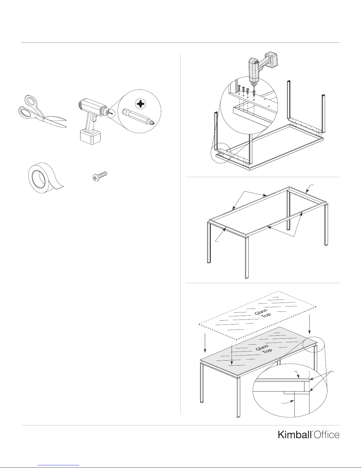
Tools Required
Scissors
Package Contents
Doudle Sided
Adhesive Tape
Installation
Screw Gun
M4 Machine Screw
#2 Phillips Head Bit
Figure A
Figure B
Tape
Tape
Note: It is recommended that three (3) persons be used for
assembling glass table units.
1. Place the worksurface frame/rails on a clean, soft surface,
underside facing up. Align the leg assembly to the eight
predrilled holes of rails and fasten. (Figure A).
2. Flip unit right side up. Cut six strips of double-sided
adhesive tape and place them along the edges of rails as
shown. DO NOT remove the film backer to expose the
adhesive at this time. (Figure B).
Note: The rails and underside of glass top MUST be clean,
dry, and free of any dirt or residue to assure adequate adhesion.
3. Carefully set glass worksurface on leg assembly. Center up
all four sides of top so that the outside edge of glass is flush
with outside edge of legs. (Figure C).
Figure C
Tape
(Full length
on ends)
Glass Top
Leg
Assembly
Tape
(6" pieces
on sides)
Flush
Proper product installation, in accordance with these instructions, is the responsibility of the installing agent.
If you have any questions concerning these instructions, please call Kimball Office Customer Service.
Part No. 2205352 Revision A-09
Fluent
Assembly Instructions
age 2 of 2
P
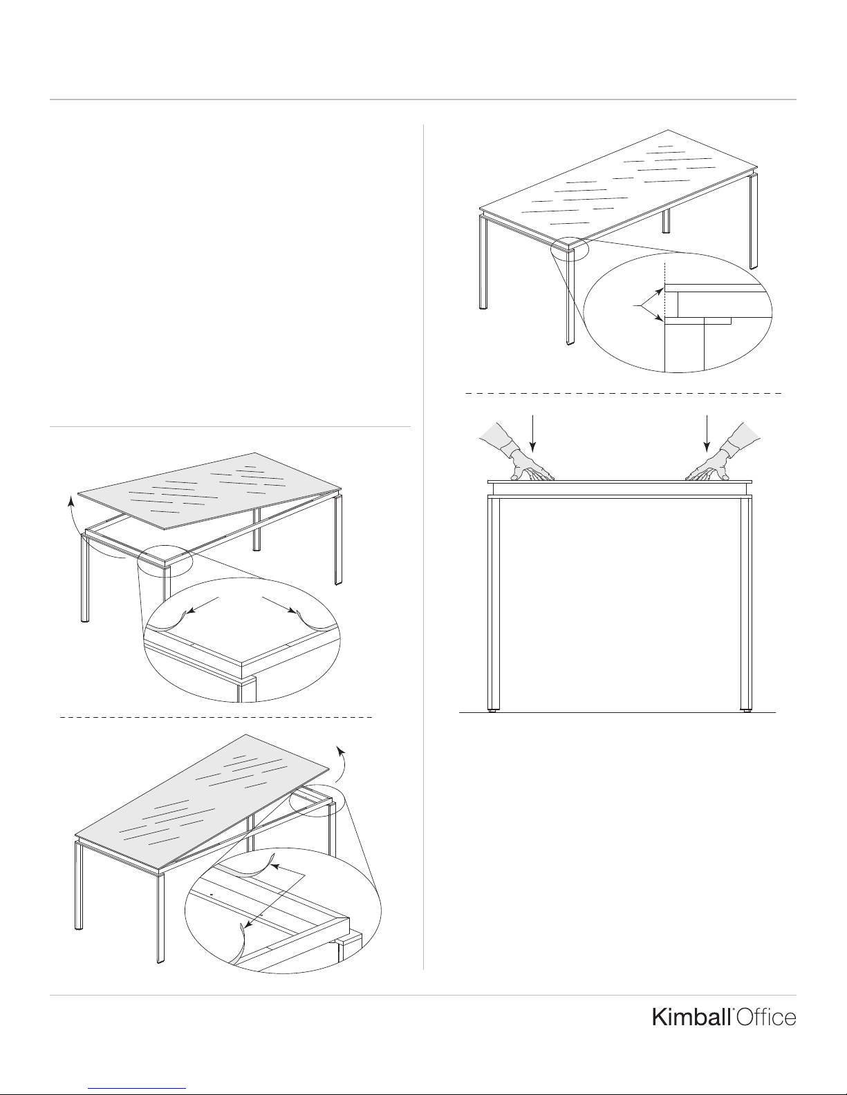
Installation (continued).
4. Step 4 requires three people. Position one person at each
end of table. While one person tilts one end of the glass
top up, the other will need to be at opposite end, securing
top in position eliminating shifting or sliding of glass top.
While the double sided adhesive tape is exposed on half of
the table, a third person will need to peel off film backer.
Now gently lower the raised end and tilt up opposite side,
careful not to move table top from side-to-side or front-to-
back. Peal off remaining adhesive film backer and lower
table top back to position. (Figure D).
5. Check that all four sides remain flush and apply direct
downward pressure on for glass top to adhere to leg
assembly. (Figure E).
Figure D
Figure E
Flush
Peel off
film backer
Peel off
film backer
Printed in U.S.A. © 2009 Kimball International, Inc. T 800.482.1818 F 812.482.8300
Proper product installation, in accordance with these instructions, is the responsibility of the installing agent.
If you have any questions concerning these instructions, please call Kimball Office Customer Service.
Part No. 2205352 Revision A-09
Fluent
Assembly Instructions
age 1 of 2
P
Drawer Removal, Adjustment,
and Unit Leveling
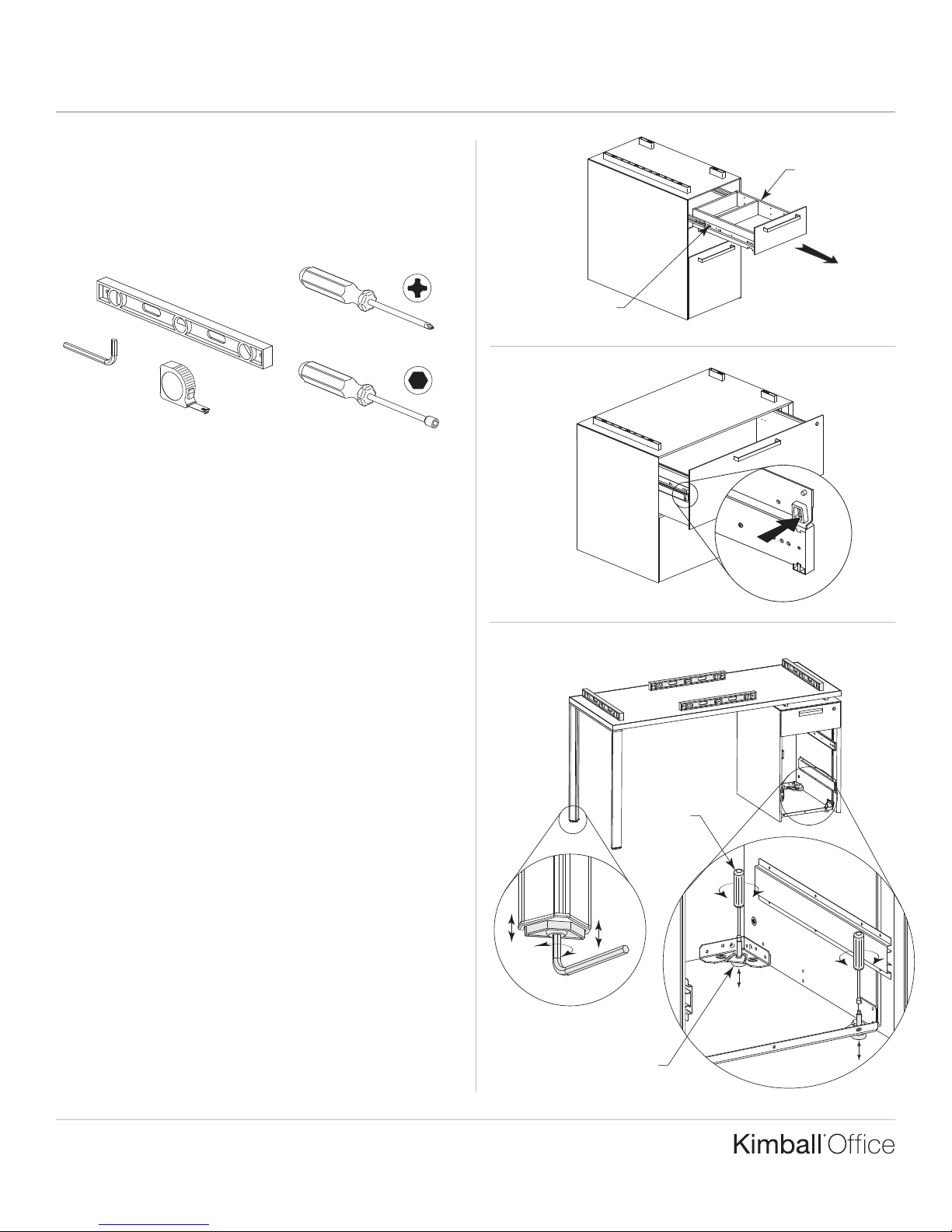
Tools Required
Level
Phillips Screwdriver
1
⁄4" Allen Wrench
7
Tape Measure
Installation
1. For Desk, Credenza, Return, Bridge, Lateral File & Drawer
or Door Storage: Remove all drawers as required to access
leveling glide adjustment holes.
2. To remove drawers: Extend the box or file drawer to its
full extension. Locate the drawer slide release tab, in the
approximate location shown, on each side of the drawer
box. Press both tabs in and pull drawer straight out until
slide drawer members disengage from cabinet members.
(Figure A).
3. To remove lateral file drawers, extend the drawer forward.
Press the two quick-disconnect release tabs and lift the
drawer off the slide assembly. (Figure B).
Note: Shipping screws must be removed from drawer
suspensions before drawer can be removed.
4. Turn the leveling glides fully “in” (counterclockwise) prior
to leveling. Level the unit from front to back by first
extending the glides on the outside corners (turn clockwise),
then level the unit from side to side. Check adjustments by
placing the level at the four positions shown. Adjust inside
glides, if applicable, to help support the unit. (Figure C).
5. Replace all drawers to their original locations. To re-install,
fully extend cabinet slide members, making sure the chrome
ball-bearing members are also forward. Carefully align
drawer slide members with cabinet slide members and
gently push drawer closed. Check for proper alignment by
inspecting drawer front margins for spacing and squareness.
⁄32" Nutdriver
Figure A
Figure B
Figure C
Release
Tabs
Level; Check
at four locations
1
⁄4" Allen Wrench
Leveling
Glides
7
⁄32"
Nut
Driver
Release
Tabs
Proper product installation, in accordance with these instructions, is the responsibility of the installing agent.
If you have any questions concerning these instructions, please call Kimball Office Customer Service.
Part No. 2205353 Revision A-09
Fluent
Assembly Instructions
age 2 of 2
P
Installation (continued)
6. If drawer front needs adjustment, open drawer and locate
the four (4) Deerwood screws that attach the drawer front
to the drawer box. (Figure D).
Note: Lateral file drawer fronts use six (6) screws.
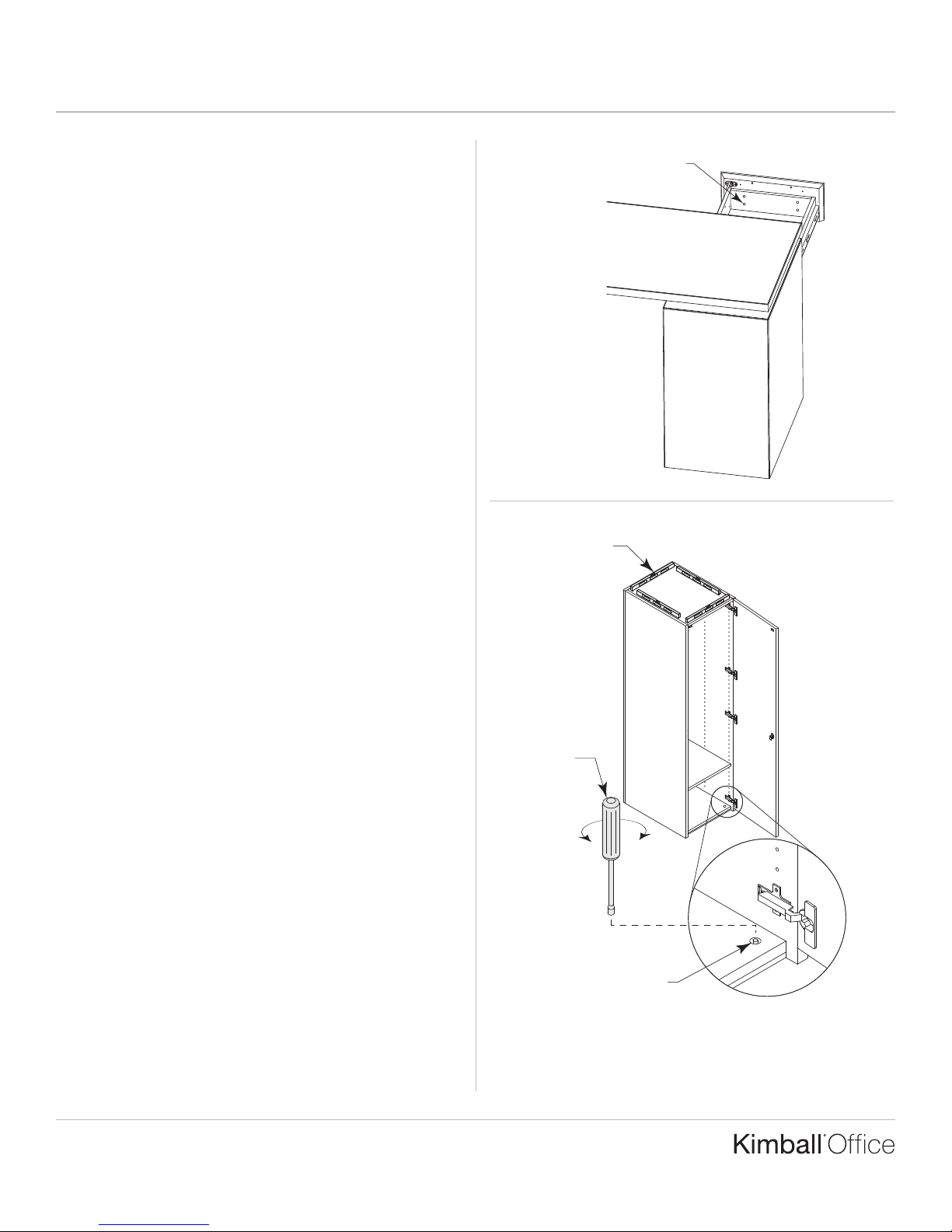
7. For Bookcase and Cabinet Storage: The lower shelf has
holes which access the leveling glides. Turn the glides fully
“in” (counterclockwise) prior to leveling. Level the unit
from front to back by extending the glides (turn clockwise).
Level the unit from side to side. Check adjustments by plac-
ing the level in the four positions shown. (Figure E).
Figure D
Deerwood Screws (4)
Figure E
Level; check
four positions
Proper product installation, in accordance with these instructions, is the responsibility of the installing agent.
If you have any questions concerning these instructions, please call Kimball Office Customer Service.
Part No. 2205353 Revision A-09
7
⁄32"
Nut
Driver
Leveling glide
adjustment hole
Printed in U.S.A. © 2009 Kimball International, Inc. T 800.482.1818 F 812.482.8300
 Loading...