

Kimax 2 Installation And Instruction Manual

KIMAX 2 Radio
Installation and Instruction manual
Software version 2.90 and up

Introduction Daily use
Table of contents
Table of contents ......................................................................................................... 2
How does it work? ........................................................................................................ 4
Daily use .................................................................................................................... 6
Kimax 2 Menu ........................................................................................................... 10
Entering the Kimax 2 menu ......................................................................................... 11
Configuration ............................................................................................................. 18
Calibration ................................................................................................................ 21
Protecting your setup and calibration ............................................................................ 25
Electrical installation ................................................................................................... 26
Serial outputs ............................................................................................................ 29
Alarms...................................................................................................................... 31
KIMAX2
Menu
Configuration Calibration
Protecting
calibration
Electrical
installation
Sensor
installation
Additional
information
Sensor installation ...................................................................................................... 32
Air sensor installation ................................................................................................. 32
SG-sensor installation (electrical installation) ................................................................. 35
Frequently Asked Questions ......................................................................................... 37
Additional information ................................................................................................. 38
Basic test setup ......................................................................................................... 40
Calibration Scheme .................................................................................................... 41
Notes ....................................................................................................................... 42
This manual is edited for the Kimax 2 Radio. The menus and diagrams are also referring to the
layout of the Kimax 2 Radio. This manual is primarily describing the standard functions for the
Kimax 2 Radio. However variations from this manual can occur. To learn more about possible
versions and special functions, visit www.kimax.com or contact your local Kimax distributor or
Sense-Tech Weighing Systems ApS.
2

Introduction Daily use
Warranty
Kimax 2 Radio is covered by Sense-Tech Weighing Systems ApS guarantee. Electronic failure
and broken components caused by normal use are repaired or exchanged when necessary,
when sent to the factory.
Damage to your vehicle caused by installation of Kimax instruments or loss of time caused by
recalibration or repairments of Kimax instruments are not covered by Sense-Tech Weighing
Systems ApS in any case.
Basic safety rules
Before you start the installation procedure, make sure that the instruments have not suffered
any damage during transport.
Note that the Kimax 2 instruments must be installed and connected in accordance
with the regulations valid for the vehicle and country in question.
The Kimax 2 instruments must be protected from gravel, water spray from wheels
and other factors that may damage the instruments.
We recommend to mount the instruments in a position where it is protected from
water jets and rinse water.
Once you have decided where the instrument is to be mounted in the cabin, you have to
consider the cable routing.
Special attention should be given to potential damaging factors such as e.g. hinging point for
tilting the cab.
Once you have decided where the instrument is to be mounted on the chassis, you have to
consider the cable routing. Special attention should be given to tensile forces, cuts and other
factors that may damage the cables and hoses.
Connection of compressed air
Before you carry out any installation work related to the air suspension, make sure
that the suspension has been brought to the lowest possible position.
Electrical connection
Always disconnect the battery before you perform any installation work on the
system of the vehicle.
KIMAX2
Menu
Configuration Calibration
Protecting
calibration
Electrical
installation
Sensor
installation
Additional
information
3
Introduction Daily use
How does it work?
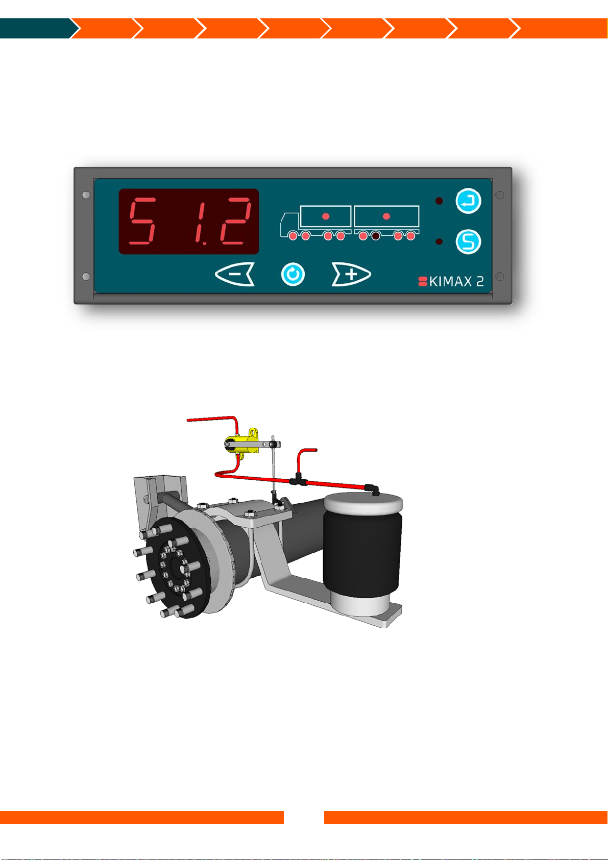
The Kimax 2 on board scale is an axle pressure meter that for instance measures the pressure
on the air suspension system to indicate the load on each axle of the entire vehicle.
The Kimax 2 Radio has a 3-digit display indicating the actual weight of the vehicle or the
weight of the individual axles. LEDs warn the driver in case of overload.
KIMAX2
Menu
Configuration Calibration
Protecting
calibration
Electrical
installation
Sensor
installation
Additional
information
A mechanical or electronic system on the vehicle maintains a fixed level of the chassis height
through a level valve which adds or subtracts compressed air to the bellows according to the
actual load on the vehicle.
The top of the bellows, shock absorber and level valve are fixed on the chassis of the vehicle.
Vehicle air supply
Air pressure input for Kimax
In order to make the Kimax 2 Radio work properly on your vehicle, you need to teach the
instrument how to calculate different loads. So before you can rely on your new on-board
scale, each axle has to be calibrated after the installation. The calibration is carried out by
weighing each axle of the vehicle on a weighing bridge. While your truck is standing on the
weighing bridge you must give in the empty weight (LO) and loaded weight (HI), when the
vehicle is empty or loaded respectively.
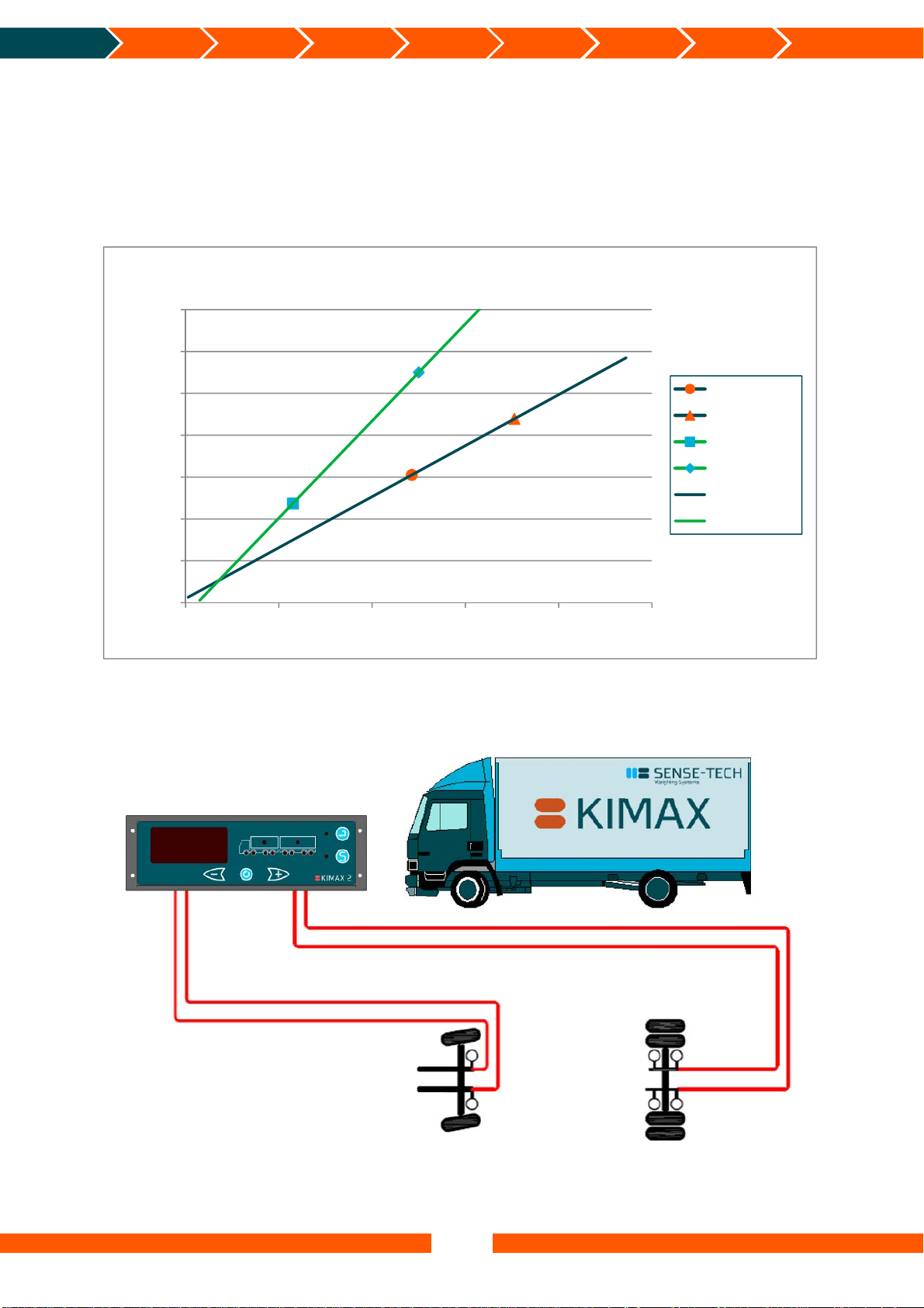
The following diagram shows an example of calibration of an air suspended vehicle with 2
axles. When the vehicle was empty, the weight of the front axle was measured on the
weighing bridge to 4,30 tons (LO value for the front axle). Equally the rear axle was measured
to 5,70 tons (LO value for the rear axle). These LO values are now entered in the LO menu of
4
Introduction Daily use
the Kimax 2 Radio. It is crucial to enter the values right away as the pressure in the air
suspension system will change when the vehicle is loaded. Now the vehicle needs to be loaded
in order to perform the HI calibration. When the vehicle was loaded, the weight of the front
axle was measured on the weighing bridge to 7,70 tons (HI value for the front axle). Equally
the rear axle was measured to 11,8 tons (HI value for the rear axle). In the same manner the
HI values are now entered in the HI menu of the Kimax 2 Radio. Again it is important to enter
the values right away, while the pressure in the air suspension system matches the loaded
vehicle. Now the Kimax 2 is calibrated.
14,00
12,00
10,00
8,00
6,00
Weight(tons)
4,00
2,00
0,00
0,00 2,00 4,00 6,00 8,00 10,00
The air pressure is measured on the right and left side of each axle and routed to the Kimax
instrument, to obtain the most accurate weighing results under different circumstances.
Kimax 2 Radio
KIMAX2
Menu
Air 1 left
Air 1 right
Configuration Calibration
Protecting
calibration
Kimax2Calibrationexample
Airpressure(bar)
Air 2 left
Air 2 right
Air 1 right Air 2 right
Air 1 left
Electrical
installation
Sensor
installation
LO‐Frontaxle
HI‐Frontaxle
LO‐Rearaxle
HI‐Rearaxle
Frontaxle
Rearaxle
Air 2 left
Additional
information
5
Introduction Daily use
Daily use
When you switch on your Kimax 2 Radio, it will show the total weight of the entire vehicle in
the 3-digit display measured in tons.
The active axle LEDs as well as the load LED are on.
When a trailer is connected to your vehicle, the active axle LEDs and load LED for the trailer is
turned on too
When you disconnect the trailer from your vehicle, the axle and load indications for the trailer
disappear after a few seconds, as well as the displayed weight is reduced by the weight of the
trailer.
1
.
KIMAX2
Menu
Configuration Calibration
Protecting
calibration
Electrical
installation
Sensor
installation
Additional
information
Enter
Save
Minus
Scroll
Plus
By use of the buttons , and , you can display the individual weight of each axle, the
load you are carrying and the total weight of your vehicle.
The following pages will give a short walk through the buttons and show you the easy way of
reading and printing values from your Kimax 2 Radio. Visit www.kimax.com, and navigate to
Support and choose Training center. There you can try the Kimax 2 emulators to experience a
live test of how you can navigate between the weighing values.
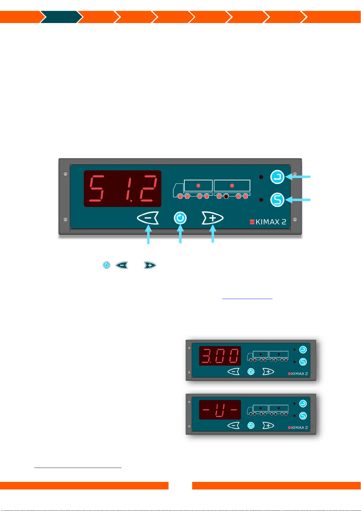
Turning on the Kimax 2 Radio
When you switch on the power for your
Kimax 2 Radio, you read a 3-digit number in
the display for about 3 seconds. The number
equals the software version of your
instrument.
Next read out is an indication of the
protection of the setup and calibration of
your instrument. The writing - L- indicates
that the instrument is protected against
changing the setup and calibration, while
-U- means that your unit is unlocked and
the calibration and setup can be changed.
1
Only if a Kimax 2 Sensor is installed on the connected trailer
6
Introduction Daily use
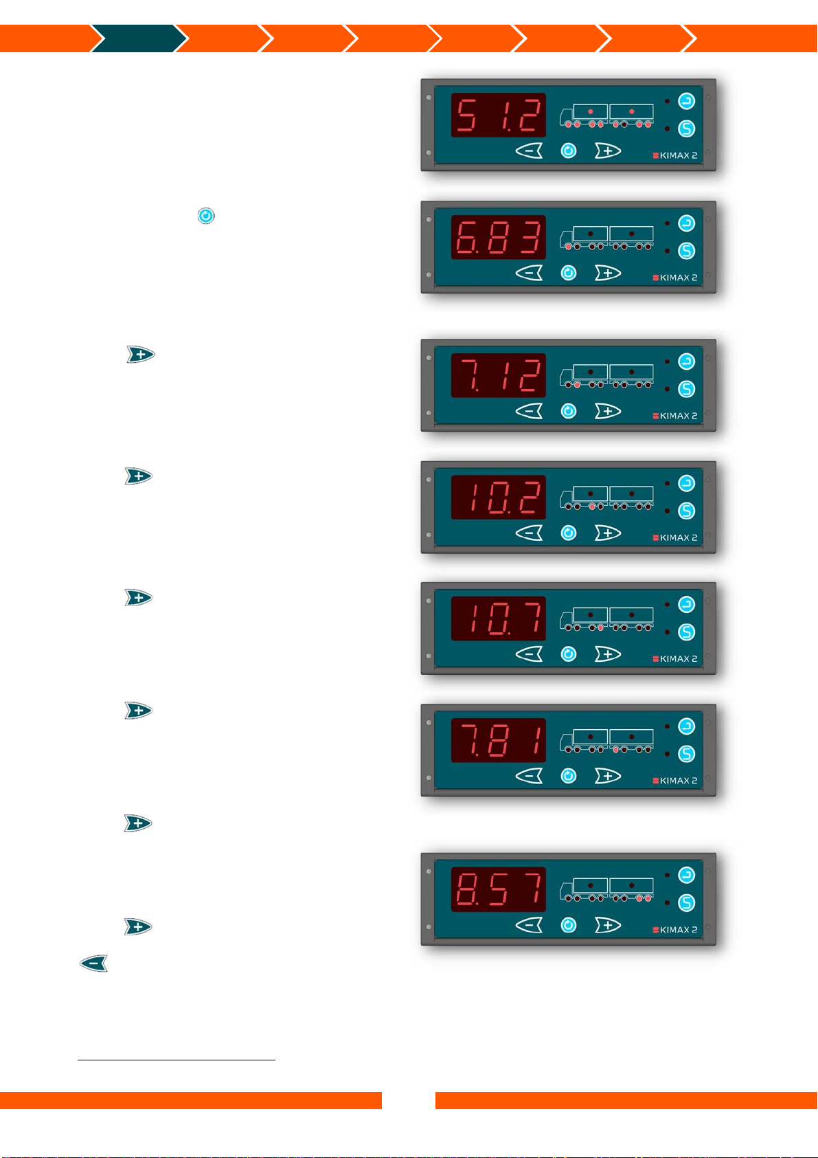
Now the instrument automatically starts
showing the total weight. (Including the
weight from a trailer, if a trailer is connected
and have a Kimax 2 Sensor installed).
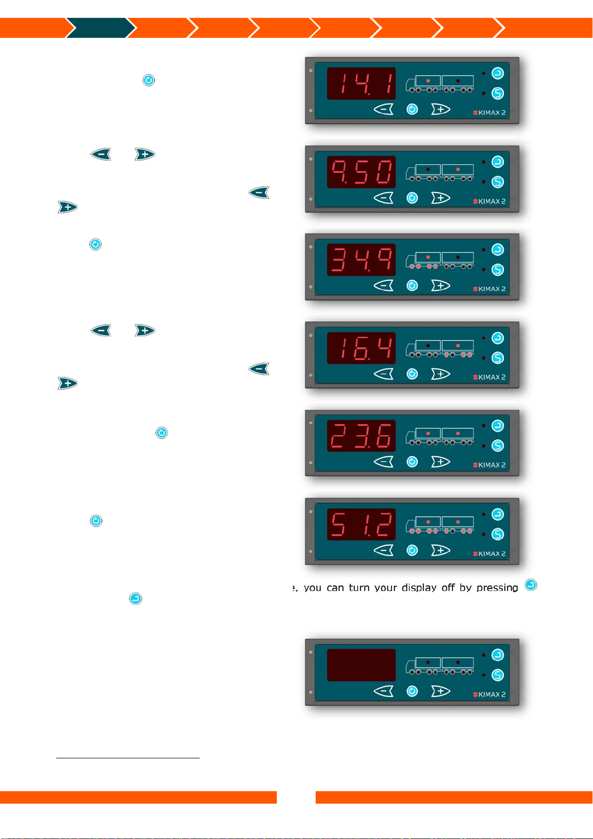
When you press once, the Kimax 2 Radio
displays the actual weight of the first active
channel, which in this case is measuring the
input from axle #1 and only the assigned
axle LED #1 is lit up.
Press once, and the instrument will
show the actual weight of the next active
channel. The shown channel is measuring
the input from axle #2 and the assigned axle
LED #2 is lit up.
KIMAX2
Menu
Configuration Calibration
Protecting
calibration
Electrical
installation
Sensor
installation
Additional
information
Press once again, and the instrument
will show the actual weight of the next active
channel. The shown channel is measuring
the input from axle #3 and the assigned axle
LED #3 is lit up.
Press once again, and the instrument
will show the actual weight of the next active
channel. The shown channel is measuring
the input from axle #4 and the assigned axle
LED #4 is lit up.
Press once again, and the instrument
will show the actual weight of the next active
channel. In this case the shown channel is
measuring the input from axle #5, which is
the first axle on the trailer and the assigned
2
axle LED #5 is lit up
.
Press once again, and the instrument
will show the actual weight of the next
active channel, which is measuring the input
from the boogie axle #6 and #7 on the
trailer. The assigned axle LED #7 and axle
LED #8 are lit up2.
Press once again and the instrument
will return to the first active channel or press
and the display will return to the
former active channel.
2
Only if a Kimax 2 Sensor is installed on the trailer. Otherwise the instrument will return to the first active channel.
7
Introduction Daily use
When you press in any of the single axle
modes, the load of the related vehicle is
shown indicated by turning on the load LED.
Press or , to toggle between the
load on your vehicle and the load on your
trailer.
When no trailer is present, pressing or
will not affect the displayed value.
Press in any of the load modes and the
total weight of the active vehicle is
displayed. This mode is displayed by turning
on both the load LED and the axle LEDs on
the active vehicle.
KIMAX2
Menu
Configuration Calibration
Protecting
calibration
Electrical
installation
Sensor
installation
Additional
information
Press or , to toggle between the
total weight of your vehicle and the total
weight of your trailer.
When no trailer is present, pressing or
will not affect the displayed value.
When you press in both of the two
former total weight modes the entire load on
your vehicle + trailer is shown.
Press once again to return to the total
weight of your vehicle + trailer.
In any of the mentioned display modes above, you can turn your display off by pressing
shortly. Press shortly once more to turn your display back on.
3
While the display turned off, the alarm outputs A2, A3, A4
, the OBC signal and the wireless4
signal is still active and broadcasted.
3
Depending on the software version. In some versions A2, A3 and A4 are disabled, when the display is turned off.
4
There will only be a wireless signal if the Kimax 2 instrument is a model with a transmitter.
8
Introduction Daily use
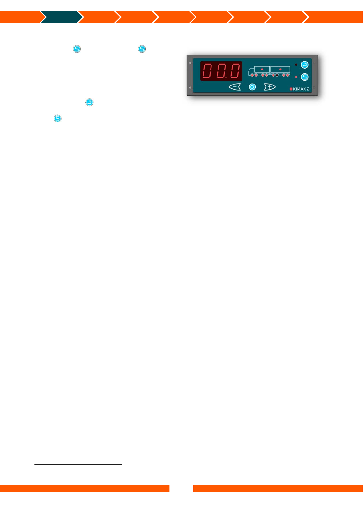
When the instrument is showing the total
5
weight
, it is possible to enter the Tare mode
by pressing . The LED next to turns on
and the value previously shown on the
display will be reset to 0,00 tons. When the
load changes (positive or negative) the
change will be shown in the display (as a
positive value). If a printer is connected to
the instrument it is possible to get a print
out by pressing . When printing from Tare
mode the Tare value will be printed as well.
Press once again to leave the Tare mode.
KIMAX2
Menu
Configuration Calibration
Protecting
calibration
Electrical
installation
Sensor
installation
Additional
information
5
Total weight in this case means, that the instrument is showing the total weight for the truck + trailer if a trailer is
connected. Otherwise it is when showing the total weight of the truck.
9
Introduction
Daily use
KIMAX2
Menu
Kimax 2 Menu
Configuration Calibration
> 2 seconds
Protecting
calibration
Electrical
installation
Submenu
See
OAA – Diagnostic menu
(on next page)
Submenu
See
VER – Software version
(on next page)
Submenu
See page 21
Submenu
See page 18
Submenu
See page 31
Submenu
See SUP – Setup
(on page 15)
Sensor
installation
Additional
information
10

Introduction
Daily use
KIMAX2
Menu
Configuration Calibration
Protecting
calibration
Electrical
installation
Sensor
installation
Additional
information
Entering the Kimax 2 menu
Through an easy to use menu, you will be able to print out the actual weight values of your
vehicle on a printer connected to the Kimax 2 system.
Furthermore, you can read some additional setup values on the display, helping you
understand how the Kimax 2 weighing system is working.
By pressing for 2 seconds, you will get access to the Kimax 2 service menu. While you are
in the menus, the LED next to will be turned on.
By pressing , when you are inside the menu, you scroll through the following menus.
When you continue scrolling until the display reads OFF, it is possible to leave the menu by
pressing .
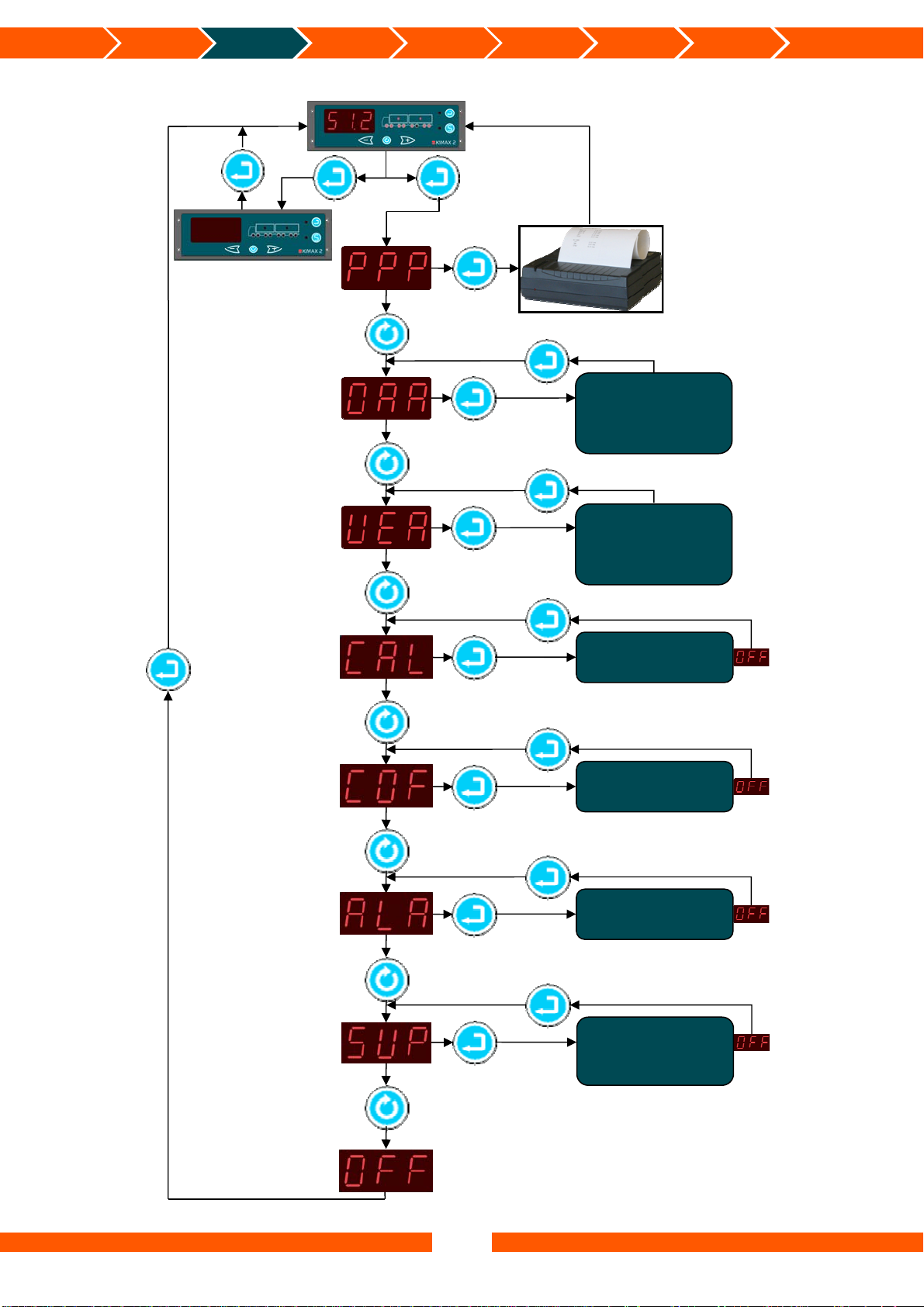
PPP - Print-out
The first position is the printing menu.
Pressing , will take you on to the next menu
position called OAA.
By pressing you will get a printed copy of
your actual load, when a printer is connected to
the Kimax 2. Hereafter the Kimax 2 leaves the
menu and returns to normal read out.
OAA - Diagnostic menu
Pressing , will take you on to the next menu
position called VER.
Press and you will enter the OAA menu,
where you get a relative value, ranging from
0,00% to 99,9%, displaying the actual sensor
value of the first active channel.
You can rotate between the active channels #1
to #8 by pressing . Press again to return
from the OAA menu.
VER - Software version
Pressing , will take you on to the next menu
position called CAL.
Press and you will enter the VER menu,
where the Kimax 2 will show the software
version of the current Kimax 2 instrument. By
pressing , it is possible to see the software
versions of the connected Kimax 2 instruments.
Press again to return from the VER menu.
11
Introduction
Daily use
KIMAX2
Menu
Configuration Calibration
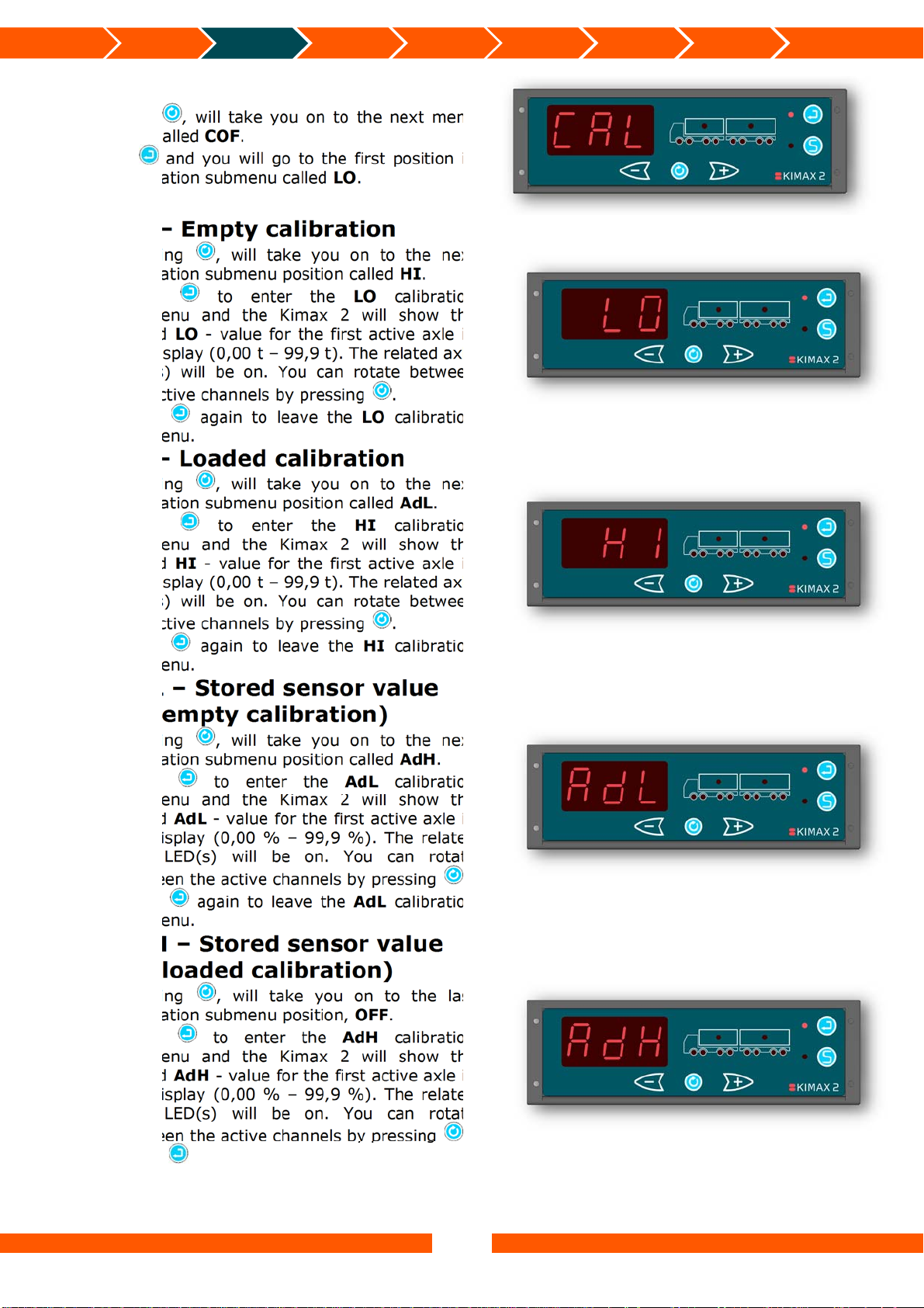
CAL – Calibration
Pressing , will take you on to the next menu
position called COF.
Press and you will go to the first position in
the calibration submenu called LO.
Protecting
calibration
Electrical
installation
Sensor
installation
Additional
information
LO – Empty calibration
Pressing , will take you on to the next
calibration submenu position called HI.
Press to enter the LO calibration
submenu and the Kimax 2 will show the
stored LO - value for the first active axle in
the display (0,00 t – 99,9 t). The related axle
LED(s) will be on. You can rotate between
the active channels by pressing .
Press again to leave the LO calibration
submenu.
HI – Loaded calibration
Pressing , will take you on to the next
calibration submenu position called AdL.
Press to enter the HI calibration
submenu and the Kimax 2 will show the
stored HI - value for the first active axle in
the display (0,00 t – 99,9 t). The related axle
LED(s) will be on. You can rotate between
the active channels by pressing .
Press again to leave the HI calibration
submenu.
AdL – Stored sensor value
(at empty calibration)
Pressing , will take you on to the next
calibration submenu position called AdH.
Press to enter the AdL calibration
submenu and the Kimax 2 will show the
stored AdL - value for the first active axle in
the display (0,00 % – 99,9 %). The related
axle LED(s) will be on. You can rotate
between the active channels by pressing .
Press again to leave the AdL calibration
submenu.
AdH – Stored sensor value
(at loaded calibration)
Pressing , will take you on to the last
calibration submenu position, OFF.
Press to enter the AdH calibration
submenu and the Kimax 2 will show the
stored AdH - value for the first active axle in
the display (0,00 % – 99,9 %). The related
axle LED(s) will be on. You can rotate
between the active channels by pressing .
Press again to leave the AdH calibration
submenu.
12
Introduction
Daily use
KIMAX2
Menu
Configuration Calibration
Protecting
calibration
Electrical
installation
Sensor
installation
Additional
information
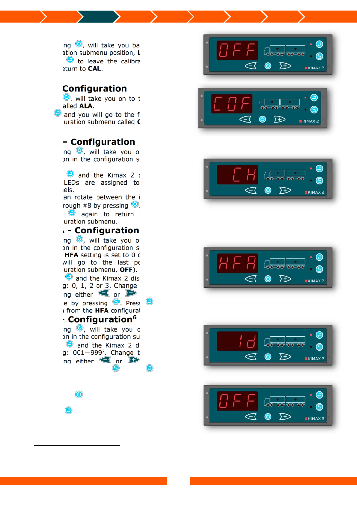
OFF
Pressing , will take you back to the first
calibration submenu position, LO.
Press to leave the calibration submenu
and return to CAL.
COF - Configuration
Pressing , will take you on to the next menu
position called ALA.
Press and you will go to the first position in
the configuration submenu called CH.
CH – Configuration
Pressing , will take you on to the next
position in the configuration submenu called
HFA.
Press and the Kimax 2 displays which
axle LEDs are assigned to which input
channels.
You can rotate between the input channels
#1 through #8 by pressing .
Press again to return from the CH
configuration submenu.
HFA - Configuration
Pressing , will take you on to the next
position in the configuration submenu called
Id (if HFA setting is set to 0 or 1, otherwise
you will go to the last position in the
configuration submenu, OFF).
Press and the Kimax 2 displays the HFA
setting: 0, 1, 2 or 3. Change this setting by
pressing either or and save the
change by pressing . Press again to
return from the HFA configuration submenu.
Id – Configuration6
Pressing , will take you on to the last
position in the configuration submenu, OFF.
Press and the Kimax 2 displays the Id
setting: 001—999
pressing either or and save the
change by pressing . Press again to
return from the Id configuration submenu.
OFF
Pressing , will take you back to the first
configuration submenu position, CH.
Press to leave the submenu and return to
COF.
7
. Change this setting by
6
Id menu is only visible if HFA is set to either 0 or 1. (Master instrument)
7
If the Kimax 2 Radio has a transmitter, make sure the Id setting on the Kimax 2 Radio and Kimax 2 Wireless
terminal are similar. If the Kimax 2 Radio doesn’t have a transmitter, the Id setting has no function. The Id setting will
however be present on a print out from a connected printer.
13
Introduction
Daily use
KIMAX2
Menu
Configuration Calibration
Protecting
calibration
Electrical
installation
Sensor
installation
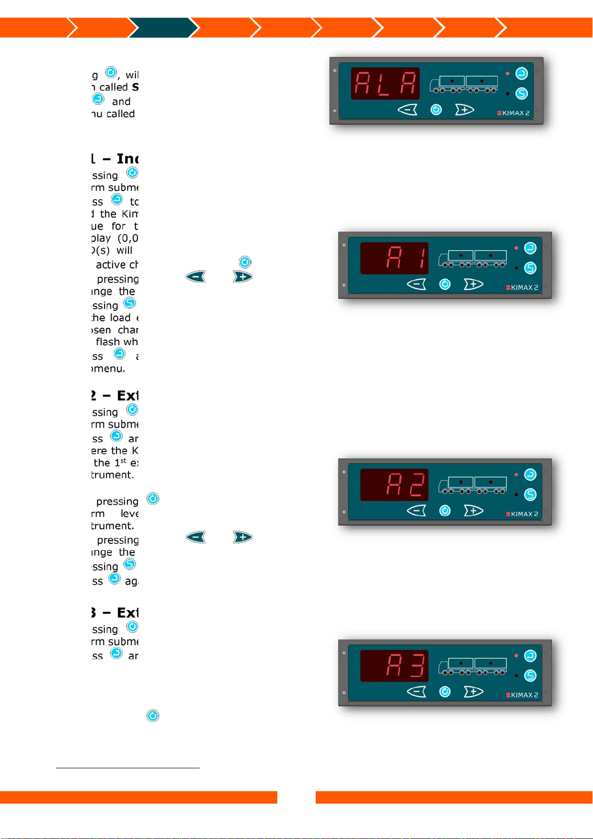
ALA – Alarms
Pressing , will take you on to the next menu
position called SUP.
Press and you will go to the first alarm
submenu called A1.
A1 – Individual Axle Alarm
Pressing , will take you on to the next
alarm submenu position called A2.
Press to enter the A1 alarm submenu
and the Kimax 2 will show the stored A1 -
value for the first active channel in the
display (0,00 t – 99,9 t). The related axle
LED(s) will be on. You can rotate between
the active channels by pressing .
By pressing either or you can
change the value and save the change by
pressing for each individual channel.
If the load exceeds the stored value for the
chosen channel the associated axle LED(s)
will flash when the Kimax 2 is in run mode.
Press again to leave the A1 alarm
submenu.
A2 – External Vehicle Alarm
Pressing , will take you on to the next
alarm submenu position called A3.
Press and you will enter the A2 menu,
where the Kimax 2 will show the alarm level
for the 1
instrument. All the assigned truck LEDs will
be on.
By pressing , it is possible to see the
alarm level for a connected trailer
instrument.
By pressing either or you can
change the value and save the change by
pressing for each instrument.
Press again to return from the A2 menu.
st
external vehicle alarm of the truck
Additional
information
A3 – External Vehicle Alarm
8
Pressing , will take you on to the next
alarm submenu position called A4.
Press and you will enter the A3 menu,
where the Kimax 2 will show the alarm level
nd
for the 2
external vehicle alarm of the truck
instrument. All the assigned truck LEDs will
be on.
By pressing , it is possible to see the
alarm level for a connected trailer
instrument.
8
Not available in all versions.
14
 Loading...