

Page 1

Kilpatrick Format
Technical Specications
Kilpatrick Format
Technical Specifications
A Specification and Guide for Module Designers
Copyright 2014: Kilpatrick Audio / Andrew Kilpatrick
Written by: Andrew Kilpatrick
07/02/2014 Page 1 of 29
web: www.kilpatrickaudio.com – email: info@kilpatrickaudio.com
Page 2

Kilpatrick Format
Technical Specications
Table of Contents
Introduction................................................................................................................................................4
A Few Words of Welcome.....................................................................................................................5
Use of the Kilpatrick Format Specification...............................................................................................6
Naming Requirements...........................................................................................................................6
Keep Kilpatrick Audio Informed...........................................................................................................6
Errors, Omissions and Suggestions.......................................................................................................6
Physical Specifications..............................................................................................................................7
Module Stack-up Overview...................................................................................................................7
Panel Material........................................................................................................................................8
Panel Retaining Screw...........................................................................................................................9
Module Power Plugs...........................................................................................................................10
Module Stack-up Details.....................................................................................................................11
Panel Dimensions and Thickness........................................................................................................12
PCB Dimensions and Thickness.........................................................................................................12
Panel to Top PCB Spacing..................................................................................................................12
Top PCB to Bottom PCB Spacing.......................................................................................................13
Enclosures................................................................................................................................................14
Module Mounting Plate.......................................................................................................................15
Power Supply......................................................................................................................................16
Active / Passive Enclosure Interconnect.............................................................................................17
Connecting Multiple Active Enclosures..............................................................................................17
Power Wiring and Power Supplies...........................................................................................................18
Analog and Digital Grounds................................................................................................................18
System Power Grounding....................................................................................................................19
Power Supplies on Modules................................................................................................................19
Audio and Control Signals.......................................................................................................................20
Signal Impedance................................................................................................................................20
Input and Output Voltage Range.........................................................................................................20
Gates and Pulses..................................................................................................................................21
Audio and CV Signals.........................................................................................................................21
Indicator LEDs.........................................................................................................................................21
Module Design Techniques......................................................................................................................22
Module Power Supply Example..........................................................................................................22
Pulse Input Circuit...............................................................................................................................23
+3.3V to +5V Pulse Amplifier.............................................................................................................24
Bi-colour LED Driver.........................................................................................................................25
07/02/2014 Page 2 of 29
web: www.kilpatrickaudio.com – email: info@kilpatrickaudio.com
Page 3

Kilpatrick Format
Technical Specications
Split Supply Using an Opamp.............................................................................................................26
Going Between AGND and DGND....................................................................................................27
Appendix A – Part Reference...................................................................................................................28
Appendix B – Module Reference Drawings............................................................................................29
Appendix C – Enclosure and Power Supply Drawings...........................................................................29
07/02/2014 Page 3 of 29
web: www.kilpatrickaudio.com – email: info@kilpatrickaudio.com
Page 4

Kilpatrick Format
Technical Specications
Introduction
The Kilpatrick Format is a unique and flexible modular synthesizer format with many useful features.
The format can be applied to modular synthesizers, audio equipment, lighting and video system, and
any system where low-power modules, straight-forward module design, high quality construction and
easy module installation and removal is desirable.
Main Features:
• 4U (7”) panel height - makes designing attractive and functional modules enjoyable
• Easy Plug-in System - makes installing and removing modules easy – no panel screws used
• Simple module construction – improves design work flow and removes guess-work – all
modules fit all enclosures
• Improved Electrical Properties – 15V rails plus separate analog and digital grounds provide a
better electrical environment for circuit designers
• Banana Cables for Patching – the use of standard banana connectors offer a high quality,
stackable, colour-coded connector which is low-cost and easy to assemble on PCBs
• Off-the-Shelf Components – no custom connectors or tooling means parts are available from
most distributors
07/02/2014 Page 4 of 29
web: www.kilpatrickaudio.com – email: info@kilpatrickaudio.com
Page 5

Kilpatrick Format
Technical Specications
A Few Words of Welcome
On behalf of Kilpatrick Audio I thank you for taking the time to get to know more about the Kilpatrick
Format. After many years searching for the “ultimate” format for my own designs I developed the
Kilpatrick Format to solve a number of problems I saw when designing for other modular systems.
After experimenting with 5U Modcan style and 3U Eurorack formats and being frustrated by both, I
realized that 4U is the “right” size for modular synths. Buchla and Serge definitely had it right, and
although I could have copied their proprietary formats, there were aspects that bothered me.
I finally came up with what I feel lends itself to easy module design. Products can be built in small
quantities. (important if you want to offer a lot of modules on a built-to-order basis) It has good
electrical characteristics, feels good physically, and uses all off-the-shelf parts which should make
boutique designs somewhat future-proof. The enclosure and power supply design are low-cost and
reliable.
I hope that you are inspired to make your own modules in the Kilpatrick Format and I look forward to
seeing and hearing what you come up with!
Andrew Kilpatrick - 2014
07/02/2014 Page 5 of 29
web: www.kilpatrickaudio.com – email: info@kilpatrickaudio.com
Page 6

Kilpatrick Format
Technical Specications
Use of the Kilpatrick Format Specification
The goal of this specification is to encourage the use the Kilpatrick Format by both commercial
manufacturers and DIY builders. Please follow the specification as closely as possible, or contact
Kilpatrick Audio if your needs are not accounted for here. With so many low-quality products available
for other formats, strict compatibility is necessary to maintain the quality of the system. If your goal is
to make the cheapest possible products then please choose a different format. However, if you want to
make excellent modules that are cost-effective and very high quality then you are probably in the right
place!
Naming Requirements
Somewhere within your advertised specifications, you must indicate that your product is a “Kilpatrick
Format” module or accessory. Use of the name means that the module or accessory meets the
requirements set out within this specification, or whichever version of the spec is current at the time
you undertake your design. This help customers who purchase modules to know that they are getting a
quality product that will work well with existing and future module designs from other manufacturers.
Keep Kilpatrick Audio Informed
Use of the Kilpatrick Format is free of charge, but you must tell us if you release a module so that we
can keep track of products available in the format. We will also offer a module swap service so that
builders can put together nice systems at low cost. When you have a module ready let us know and
we'll arrange to swap a module of similar value with yours. We hope you will extend this opportunity to
other builders as well.
If you don't want to trade modules, sending some info that we can post on our website would be great
also. We are interested in linking to both commercial and DIY sites if you want to become part of the
family. Prospective buyers often ask what other modules are available.
Errors, Omissions and Suggestions
Please help to improve this specification by reporting any errors, information that is missing or difficult
to understand, and any other ideas that would help to improve it.
07/02/2014 Page 6 of 29
web: www.kilpatrickaudio.com – email: info@kilpatrickaudio.com
Page 7
Kilpatrick Format
Technical Specications
Physical Specifications
The Kilpatrick Format is built around panels which are one or more spaces wide. A space is set as 1/4
of a rack width, and 4U (7”) tall. Four spaces occupy one rack-mountable enclosure. Wider enclosures
are possible, with 5 or 6 spaces being the most useful. Spaces are 4.250" x 7.000", but panels are
manufactured as 4.240" x 6.990" to compensate for slight manufacturing tolerances and also alignment
when the modules are plugged into the system. The dimensions should be reduced by 0.005” on each
edge so that all holes, etc. are centered within the panel.
One and two space panels are the most useful sizes, although three and four spaces can be made as
well. You must not make modules wider than four spaces because all modules should fit into a
rack-mounted enclosure. The corners of modules are always rounded with a 0.125” radius to make
them less sharp and also hide small alignment problems when the modules are sitting next to each
other. If you have an idea for a huge module it might make more sense to break it up into several
smaller designs.
Module Stack-up Overview
Before we go into detail on the each part of a module, have a look at the following diagram which
shows the components of a module as a section view. All modules are built with the same stack-up and
spacing between layers.
Fig 1 - Module Stack-up – Side View
07/02/2014 Page 7 of 29
web: www.kilpatrickaudio.com – email: info@kilpatrickaudio.com
Page 8
Kilpatrick Format
Technical Specications
The spacings are chosen to allow the use of common components such as banana jacks, toggle
switches, board to board stacking headers, etc. Some components like pushbuttons and some kinds of
jacks may require additional PCBs or different spacings, but for most modules the suggested spacing
should offer the most flexibility.
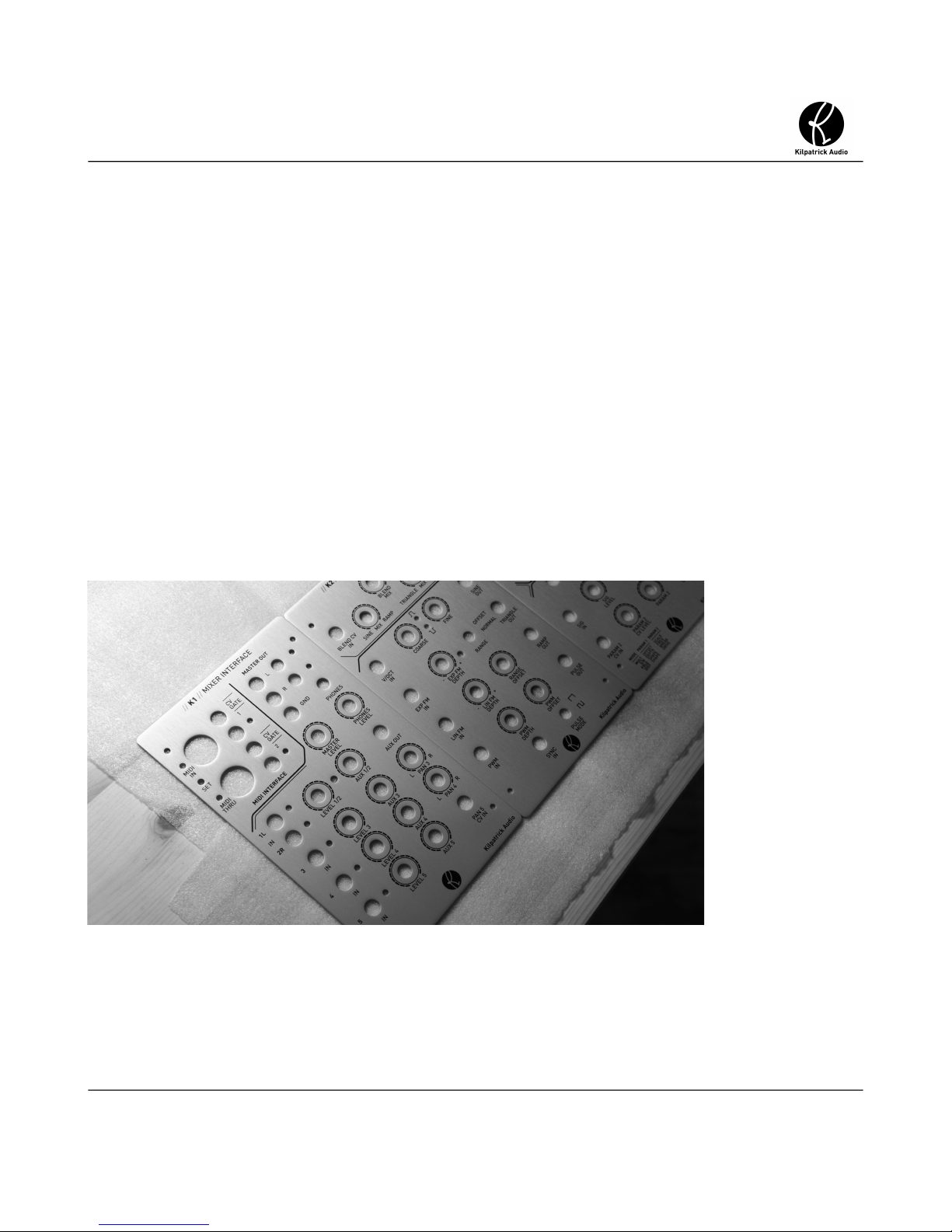
Panel Material
Panels are generally made from 14GA (0.062" or 1/16” thick) anodized aluminum. Kilpatrick panels
are vertically brushed and anodized and screened with black epoxy ink. Other finishes are acceptable
such as powder coating. Panels must be made from metal. The panel thickness must be 0.062” to
ensure that all module faces are aligned when installed in a system.
Note: The use of PCB material or acrylic as a panel material is not acceptable. If these materials
are required for specific reasons, they should be installed within an area of a metal panel and not
used to support the banana jacks or mounting bolts.
Fig 2 - Raw Panels
07/02/2014 Page 8 of 29
web: www.kilpatrickaudio.com – email: info@kilpatrickaudio.com
Page 9
Kilpatrick Format
Technical Specications
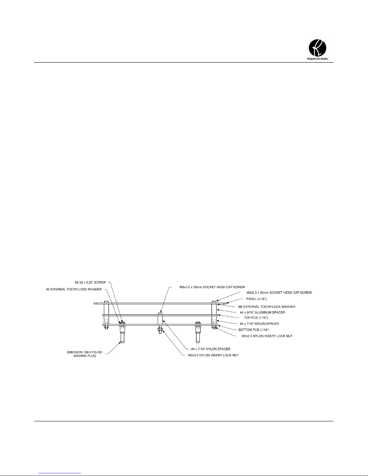
Panel Retaining Screw
Below each module space in an enclosure is a blind M3x0.5 standoff used to secure a module to the
enclosure. Each module must contain a captive M3x0.5 x 25mm hex head cap bolt that uses a 2.5mm
hex key. The bolt is installed between the two PCB layers with a spacer between PCBs. The retaining
feature is accomplished by a nylon insert lock nut underneath the PCB. A hole in the top panel gives
access to the bolt. The module can be secured by gently tightening the bolt. When banana cables are
pulled out many at a time, the bolt keeps the module from pulling out of the enclosure. In production
the nut should be tightened part way to allow some play in the bolt. The spacer prevents
over-tightening and damage to the PCBs.
Fig 3 - Retaining Screw – Side View
07/02/2014 Page 9 of 29
web: www.kilpatrickaudio.com – email: info@kilpatrickaudio.com
Page 10

Kilpatrick Format
Technical Specications
Module Power Plugs
The main parts that secure a module into an enclosure are the power plugs. The plugs are male banana
plugs of the same type used for panel patching. These are available as metal plugs supplied with #6-32
bolts which screw into the back of the plug. Four plugs are secured to the PCB using additional internal
toothed lock washer on the top side of the lower PCB. Locktite blue (medium strength) is used
sparingly on each bolt to help keep the bolts from loosening, but not enough to prevent good electrical
contact as the bolts are used to couple power to the lower PCB.
The plugs supply the four power signals: +15V, -15V, AGND and DGND. Note that the AGND plug is
aligned differently, thus providing a keying to prevent backwards installation.
Fig 4 - Power Plugs – Bottom PCB - Top View
07/02/2014 Page 10 of 29
web: www.kilpatrickaudio.com – email: info@kilpatrickaudio.com
Page 11

Kilpatrick Format
Technical Specications
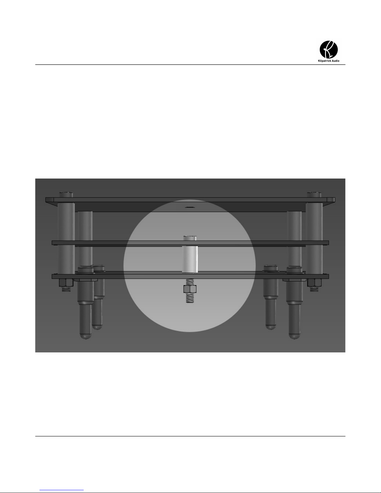
Module Stack-up Details
The module stack-up is integral to the physical robustness and overall height of a module. The module
assembly is designed to use standard components and be easy to assemble. The spacing between the
panel and PCBs is a compromise, but must be kept within a tight tolerance to avoid height problems
when plugging the module into an enclosure.
Fig 5: Module Stack-up - Side View
Notes about the photo:
• LED spacers used throughout
• banana jacks metal tab soldered to top PCB through 0.197” hole
• 30mm pots and standard toggle switches can be used
• shorter parts and specialty displays, etc. should use daughter PCB mounted to top PCB
07/02/2014 Page 11 of 29
web: www.kilpatrickaudio.com – email: info@kilpatrickaudio.com
Page 12

Kilpatrick Format
Technical Specications
Panel Dimensions and Thickness
The panels are nominally 14GA aluminum 0.062” (1/16”) thick. A brushing / anodizing operation
usually removes a small amount of material. The overall dimensions of a single-space panel is 4.240”
wide and 6.990” tall. Each of four corners is rounded off with a 0.125” (1/8”) radius. Detailed drawings
can be found in Appendix B of this document.
PCB Dimensions and Thickness
All PCBs are nominally 0.062” (1/16”) thick. Including 1oz copper and a solder mask this thickness is
actually about 0.067”. The overall dimensions of a single-space PCB is 4.100” wide and 6.100” tall.
Detailed drawings can be found in Appendix B of this document.
Wider PCBs can be made for modules of 2-4 spaces. In the case of wider modules some of the power
connections can be omitted. For instance in a 3 space module power plugs are used on space 1 and 3
but not in the center (2) space. Similarly only two retaining bolts are used.
Panel to Top PCB Spacing
The spacing from the panel to the top PCB is nominally 0.562” (9/16”) plus the thickness of an M3
external tooth lock washer. The overall height is approx. 0.587”. Round, un-threaded aluminum spacers
are used between the panel and top PCB to create a ground connection to the top panel. The external
tooth lock washer ensures a good connection since anodized panels are non-conductive on the surface.
The metal panel is always connected to AGND so that the entire system is shielded.
The spacing from the panel to the top PCB allows standard Emerson banana jacks to be soldered to the
top PCB. It also allows the use of standard mini toggle switches. For shorter components like
pushbuttons, etc. a small sub-assembly PCB may be required to support these types of components
closer to the panel. How this is implemented is up to the designer.
07/02/2014 Page 12 of 29
web: www.kilpatrickaudio.com – email: info@kilpatrickaudio.com
Page 13

Kilpatrick Format
Technical Specications
Top PCB to Bottom PCB Spacing
The spacing from the top PCB to the bottom PCB is nominally 0.437”. (7/16”) Nylon spacers are used
between the top and bottom PCBs for low-cost. A spacer is required in each of four corners plus one in
the center where the retaining screw is held captive.
Connecting signals between the top and bottom PCBs is possible by using standard 0.100” stacking
header connectors. Kilpatrick Audio uses 20 pin single-row connectors on all designs. The possible
location of the headers is chosen per design. Alternately a dual-row header could be used for denser
modules. The combination of a standard male and female header results in precisely 0.437” (7/16”)
spacing between PCBs.
When choosing stacking headers, the male header protrudes from the bottom of the top module, and the
female header protrudes from the top of the bottom module. This ensures that during prototyping,
assembly and testing, sensitive circuits on the bottom PCB do not have their pins exposed. Top PCBs
usually only contain passive parts and LEDs.
Fig 6: Module Stacking Headers
07/02/2014 Page 13 of 29
web: www.kilpatrickaudio.com – email: info@kilpatrickaudio.com
Page 14

Kilpatrick Format
Technical Specications
Enclosures
Enclosures are designed to be low-cost and easy to manufacture in small quantities. The existing
Kilpatrick Audio enclosure and power supply design is offered for use free-of-charge and drawings are
available in Appendix C of this document. These included drawings are for reference only. For the
latest drawings including DXF or IGES files of the enclosure for metal manufacturers please contact
Kilpatrick Audio or see our website for download info.
Fig 7: Enclosure - 4 Space Active Enclosure
07/02/2014 Page 14 of 29
web: www.kilpatrickaudio.com – email: info@kilpatrickaudio.com
Page 15

Kilpatrick Format
Technical Specications
Module Mounting Plate
The main part of the enclosure serves only to cover the sides of the modules and provide mounting
points to attach rack ears or stacking brackets for connecting two enclosures together. The important
interface between the modules and the enclosure is through the module mounting plate. This part is
mounted in the bottom of the enclosure on 0.875” (7/8”) standoffs which provide an electrical
connection to the main enclosure, as well as supporting the plate at the correct height for modules to be
installed. #6 internal tooth lock washers used between the top and bottom screws and the metal ensures
a good electrical connection so that the entire chassis is grounded to AGND.
Fig 8: Module Mounting Plate - Top View
Notes about the photo:
• banana jack colours are:
◦ +15V = red
◦ -15V = grey
◦ AGND and DGND = black
07/02/2014 Page 15 of 29
web: www.kilpatrickaudio.com – email: info@kilpatrickaudio.com
Page 16

Kilpatrick Format
Technical Specications
Underneath the plate is ample room for wiring the module power jacks, inlet power socket, switch,
power LED, and the actual power supply PCB. The power supply is mounted upside-down on the
underside of the module mounting plate which protects it and the associated wiring.
Fig 9: Module Mounting Plate Underside - Active Type
Power Supply
The power supply is a very simple module using an off-the-shelf DC-DC converter. The power input
must be regulated +15V and is simply passed through a reverse polarity protection diode (Schottky
type) and filtered. This raw supply is fed to the +15V jack on every module. The on-board DC-DC
module produces -15V with 10W max. output. This is filtered and fed to the -15V jack on every
module.
This scheme offers limited -15V power (but plenty for most designs) but allows the +15V supply to be
increased simply by using a larger external power supply. For digital modules that contain embedded
computers, for instance, it might be necessary to have many watts of power on a single module. The
most economical route to this is to allow the end-user to upgrade their external adapter. A 24W unit is
supplied by Kilpatrick Audio and is suitable for up to eight modules. The typical wiring in a system
should handle +15V at 40-60W (3-4A) without any trouble. The input protection diode for the system
is rated for up to 7.5A, and designers who wish to build their own power supplies should keep in mind
that users may want to upgrade their +15V power supply at a later time for higher power use.
Note: The use of ungrounded (2-wire) external power supplies is preferred over grounded types. (more
on this below)
07/02/2014 Page 16 of 29
web: www.kilpatrickaudio.com – email: info@kilpatrickaudio.com
Page 17

Kilpatrick Format
Technical Specications
Active / Passive Enclosure Interconnect
The enclosure is designed with front/rear and bottom cutouts to allow flexibility in wiring the DC
power and inter-enclosure power cables. Normally two enclosures are used together. The top one
contains the power supply and is called the active enclosure whereas the bottom enclosure is passive
and contains wiring only. Connectors on the module mounting plate allow a short cable to be attached
to the front or rear of the plate. Four wires are needed to connect active and passive enclosures together.
For very low-power modules such as MIDI controllers, it might be possible to connect two or even
three passive enclosures to a single active enclosure. Passive enclosures can be installed above or
below the main enclosure, but generally they are installed below because this allows better access to
the power input jack and power switch on the rear of the active enclosure.
An important note about grounding is that the digital ground (DGND) from all modules and enclosures
is returned to the power supply PCB where it is connected to analog ground (AGND) at a single point.
This prevents ground loops and noise from being injected into sensitive circuits. AGND and DGND
must never be tied together except at the power supply PCB of an active enclosure.
Connecting Multiple Active Enclosures
If a system grows beyond eight modules it is likely to require more than one active enclosure. In this
case it is necessary to connect the ground between the two systems. A black banana jack is provided on
the rear of each enclosure which is internally connected to AGND. A standard banana patch cable can
be used to connect multiple sets of enclosures together. Each active enclosure requires its own external
power supply.
07/02/2014 Page 17 of 29
web: www.kilpatrickaudio.com – email: info@kilpatrickaudio.com
Page 18

Kilpatrick Format
Technical Specications
Power Wiring and Power Supplies
Power wiring within a system uses a simple methodology which keeps wires short. In most cases the
wiring between modules within a single enclosure are daisy-chained. These groups of jacks are then
attached to the connectors which feed to the next and previous enclosures, and to the power supply in
the case of an active enclosure.
The topology is not particularly important for the most part. The most crucial aspect is that analog
ground (AGND) and digital ground (DGND) must be kept separate throughout an entire system and
only joined together at a single point within the power supply. Systems with multiple powered
enclosures must have their analog grounds connected together. Each module has an analog ground
connection (banana jack) on the back of the enclosure for this purpose.
Analog and Digital Grounds
For optimum CV and audio performance it is crucial that noisy signals and larger loads which switch
on and off not be allowed to interfere with sensitive signals. Because banana cables are a single wire,
the signal return (analog ground) is provided inside the enclosure. Thus any noise on the internal return
will be added to the patched signal. Large or noisy loads within a module that draw current in and out
of the ground connection will cause voltage drops on the ground wiring within a system which will be
added to CV and audio signal paths.
The Kilpatrick Format system uses separate analog and digital grounds (AGND and DGND) to solve
this problem. Analog grounds are used for signal returns, references for analog circuits, ADCs and
DACs, and other low-noise circuits.
Digital grounds are used for noisy circuits such as DC-DC converter grounds, microcontroller power
supplies, LED grounds and other loads that could be noisy. In most cases it is easy to keep these two
grounds separate except in a few cases which will be covered in detail in the Module Design
Techniques section.
Power supplies (+15V and -15V) are shared between both analog and digital circuits. These supplies
are also not guaranteed to be quiet or particularly well regulated meaning that they should never be
used to directly power sensitive circuitry. Instead every module uses local voltage regulators and power
supplies to deliver voltages to the various stages. A typical hybrid module containing both analog and
microcontroller circuitry might have the following supplies:
• +12V and -12V linear voltage regulators for op amp supplies –fed from +15V and -15V
• +3.3V DC-DC buck converter for microcontroller power supply – fed from +15V
• +3.3V linear regulator connected to the +12V supply for ADC and DAC power supplies
07/02/2014 Page 18 of 29
web: www.kilpatrickaudio.com – email: info@kilpatrickaudio.com
Page 19

Kilpatrick Format
Technical Specications
System Power Grounding
One flaw of many modular systems is the use of a grounded power cord. Although this may be required
for regulatory purposes, it often causes ground loops and hum in typical systems. Almost always a user
will have a computer and/or a mixing console which will be grounded to the electrical supply. (third
prong) Kilpatrick Audio uses power supplies that require only two wires. The audio cables provide a
ground reference from the studio mixing console, and no ground loops exist within the system.
In higher power systems where a two prong power supply is not possible, or where the synthesizer is
the central mixing point for an entire system it may be preferable to use a grounded power supply. But
generally power supplies with 2-prong input plugs will offer the best noise and hum performance in a
typical setup.
Power Supplies on Modules
It is important that the voltage drop and tolerance of the main power supply and linear regulators on
modules be taken into account. Kilpatrick Audio modules use Schottky diodes on both the main power
supply and also the +15V and -15V inputs on each module. This offers minimal voltage drop and
permits the use of standard linear voltage regulators for +12V and -12V.
For +3.3V linear supplies for DACs and the like, using the +12V regulated supply will enable more
choices of low voltage regulators as they have to withstand a lower maximum input voltage than if they
were fed from the +15V input.
Input filtering on modules should be moderate to avoid excessive capacitance on the supplies for a full
system. Particularly on the -15V side, many DC-DC converters have a maximum capacitance they can
handle on the load. Kilpatrick Audio uses 100uF for the +15V supply on each module and 10uF for the
-15V on each module. These capacitors are installed after the input protection diodes. As the input is
already smooth DC this has proven more than adequate.
07/02/2014 Page 19 of 29
web: www.kilpatrickaudio.com – email: info@kilpatrickaudio.com
Page 20

Kilpatrick Format
Technical Specications
Audio and Control Signals
Audio and control signals are interchangeable on a Kilpatrick Format system. There are two types of
signals and four types of jacks. The jack colours used on modules must follow the same standard.
Additional colours can be used for jacks which serve a different purpose such as interfacing other kinds
of non-audio or CV signals.
• Gate / Pulse Signals – A gate or pulse signal is 0V when off and 5V when on. These are output
on red banana jacks and input on white jacks. Inputs should be set up to trigger when the
voltage is above about 1V.
• Audio / CV Signals – Audio and CV signals range from about -5V to +5V nominally. These
signals are output on grey banana jacks and input on black jacks. An oscillator or LFO should
output a 10Vpk-pk signal. (-5V to +5V) The center point in the range of an input is 0V, thus
when a cable is disconnected the input should be terminated so that it defaults to 0V.
• Pitch CV Signals – Pitch signals calibrated to musical pitch are specified as 1V/octave. 0V is
the centre of the range, with +5 and -5 octaves (volts) possible.
Signal Impedance
All outputs must have an output impedance of 1K ohm or less. A 1K series resistor is the most common
way to lead a signal out to a jack. For pitch outputs specifically the output impedance should be 100
ohms. This helps to avoid tuning errors with pitch oscillators.
All inputs must have an input impedance of 20K ohms or more. Generally 30-50K is best as this allows
multiple inputs to be fed from a signal output without appreciable loss of signal level. Pitch V/octave
inputs on oscillators should have an input impedance of 100K or more.
Grounded when off: All outputs should be grounded when the circuit is off. This is especially true for
modules that interface with other audio equipment such as mixers and interfaces. Trace back the signal
from the output to ensure that it has a resistive path to ground of less than a few hundred K ohms. If not
be sure to terminate the output. Ensure that the output termination does not introduce unwanted voltage
drop at the output jack.
Input and Output Voltage Range
Signals are nominally -5V to +5V. However a typical TL084 or similar op-amp running off a +/-12V
supply can produce outputs of at least -10V to +10V. This range of voltages is completely acceptable in
the case of a circuit which adds gain to a signal.
Inputs should be designed to withstand -15V to +15V without damage. Inputs with attenuators can
accept any voltage range and allow the user to adjust the sensitivity of the input. Inputs without
attenuators should be carefully set up so that an input of -5V to +5V cause the full range of desired
07/02/2014 Page 20 of 29
web: www.kilpatrickaudio.com – email: info@kilpatrickaudio.com
Page 21

Kilpatrick Format
Technical Specications
control. If in doubt a slightly smaller range which clamps at the endpoints is more desirable than a
wider range which requires a larger input signal to reach all possible input values.
Gates and Pulses
A gate is used for controlling an envelope generator or other type of input which is held in an “on” state
while the gate is high.
A pulse is used to trigger a condition like causing an event to occur or restarting a sequencer. A pulse
should be high for at least 1ms to allow the receiving device to “catch” it.
Audio and CV Signals
An audio signal is at the nominal level when it is 10Vpk-pk. This offers the best noise immunity
however the headroom is limited to only about 6dB. Filters, mixers and other modules that increase the
signal level should be designed to “save” some headroom by attenuating the input signal internally.
An envelope or other signal which has a range of lowest to highest value should range from -5V to
+5V, with -5V being the “at rest” state in the case of an envelope generator. This may seem odd but it
maintains compatibility between all kinds of signals. When an envelope is triggered it rises from -5V,
through 0V to +5V and then back down again. VCAs and VCFs should be designed to handle this
range of input. This solves a common problem on other systems where there are both unipolar and
bi-polar signals which are not inter-compatible.
Indicator LEDs
Although the display and user interface choice is up to the designer, several LED colour standards have
been adopted by Kilpatrick Audio to help differentiate various signal types. It is not mandatory to use
the same colours but it might help to make a module seem more familiar along side other modules.
• Red LEDs – For modes, on-off settings, pulses and gates generally red LEDs are used.
• Clear amber LEDs – For audio signal levels clear amber LEDs are used to show the relative
level.
• Bi-colour red/green LEDs – For bi-polar signal indicators on envelope generator outputs or
other circuits where the amplitude and polarity of a signal is important a bi-colour LED is used.
Red means negative and it gets brighter with more negative signal. Green means positive and
gets brighter with more positive signal. At 0V neither LED is lit. A two-lead LED is used with
back-to-back LEDs so that it can be easily driven from a signal op-amp output.
07/02/2014 Page 21 of 29
web: www.kilpatrickaudio.com – email: info@kilpatrickaudio.com
Page 22

Kilpatrick Format
Technical Specications
Module Design Techniques
Good module design techniques and “best practice” rules will help to ensure maximum compatibility
between modules from different manufacturers. Some tips and tricks are shown here which might be
useful. Some are just good engineering practice and others were devised for the Kilpatrick Format and
seem to work well.
Module Power Supply Example
Fig 10 - Power Supply - Example +/-12V
Notes about the example:
• D5,6 are Schottky diodes for minimal voltage drop
• C16 is 10uF to prevent too much capacitance on -ve supply
• D1,2 help to protect the module in case one of the grounds is missing – standard silicon diode is
used for low capacitance (10pF for a 1N4001)
07/02/2014 Page 22 of 29
web: www.kilpatrickaudio.com – email: info@kilpatrickaudio.com
Page 23

Kilpatrick Format
Technical Specications
Pulse Input Circuit
Fig 11 - Pulse Input Circuit
Notes about the example:
• input resistors set the input impedance at approx. 40K and also shift the threshold voltage to just
over 1V for a typical small signal transistor
• diode prevents negative base voltage
• transistor collector can be pulled up to whatever voltage the output needs
• output signal is inverted
07/02/2014 Page 23 of 29
web: www.kilpatrickaudio.com – email: info@kilpatrickaudio.com
Page 24

Kilpatrick Format
Technical Specications
+3.3V to +5V Pulse Amplifier
Fig 12 - +3.3V to +5V Pulse Amplifier
Notes about the example:
• input and output are in phase
• different configurations can be chosen for different gain and offsets
• a simple unity gain buffer can be used for +5V signals
07/02/2014 Page 24 of 29
web: www.kilpatrickaudio.com – email: info@kilpatrickaudio.com
Page 25

Kilpatrick Format
Technical Specications
Bi-colour LED Driver
For a bi-colour LED driver it is easy to use an op-amp to drive an LED. Usually a separate amplifier is
used for the LED because the load changes depending on whether the LED is in conduction or not.
This could cause distortion if the same amplifier were used for signal output as well. In many cases,
however simply using a single amplifier is sufficient.
Fig 13: Bi-colour LED Driver with 2 Amps
Note: Most of the circuitry driving a bi-colour LED will be referenced to AGND. However the cathode
of the LED should be tied to DGND. This prevents the large LED current from returning into AGND
and potentially causing voltage drops on signal returns.
07/02/2014 Page 25 of 29
web: www.kilpatrickaudio.com – email: info@kilpatrickaudio.com
Page 26

Kilpatrick Format
Technical Specications
Split Supply Using an Opamp
Fig 14: Split Supply Op-amp Circuit
Notes about the example:
• for making low current split references
• useful for powering 4000 series CMOS muxes which require <20V
• voltage is easily adjusted with a resistor divider
• small filtering and bypassing should be used at loads
07/02/2014 Page 26 of 29
web: www.kilpatrickaudio.com – email: info@kilpatrickaudio.com
Page 27

Kilpatrick Format
Technical Specications
Going Between AGND and DGND
When going between AGND and DGND references it is important to avoid a condition where the two
supplies are at very different voltages. To protect against this condition in case of a missing power
connection, modules which use both AGND and DGND include a pair of back-to-back 1N4001 silicon
diodes between grounds. These diodes have very low capacitance to avoid coupling noise between
grounds, and also require an imbalance of around 0.6V in either direction before they will conduct.
For ADC and DAC digital signals connecting between microcontrollers or DSPs (on DGND) and the
converters (on AGND) some series resistors (100 ohms works for speeds up into the MHz) will prevent
excessive current flow in case the chip supplies on each side are not equal. This is also good practice to
help absorb reflections and minimize EMI.
07/02/2014 Page 27 of 29
web: www.kilpatrickaudio.com – email: info@kilpatrickaudio.com
Page 28

Kilpatrick Format
Technical Specications
Appendix A – Part Reference
Type Manufacturer Manufacturer Part Notes
pot – single gang Alps RK09D1130A1N most standard pots
pot – stereo audio Alps RK12L12C0A0G stereo volume pots
3mm amber LED Lite-On LTL1CHKYKNN signal levels
3mm red LED Lumex SSL-LX3044LID pulses, gates, modes
3mm red/green LED Kingbright WP937EGW bi-polar indicators
+12V regulator ON Semiconductor MC78L12ACPG analog supply
-12V regulator ON Semiconductor MC79L12ACPG analog supply
small pushbutton TE FSM16JH configuration, resetting, test
LED spacer (0.500”) Bivar LTM-500 all LEDs
stacking header (male) FCI 68001-220HLF board to board
stacking header (female) Sullins PPPC201LFBN-RC board to board
banana jack (black) Emerson 108-0903-001 audio / CV input
banana jack (grey) Emerson 108-0913-001 audio / CV output
banana jack (white) Emerson 108-0901-001 pulse / gate input
banana jack (red) Emerson 108-0902-001 pulse / gate output
banana plug (module
power)
3.5mm minijack CUI SJ5-43502PM audio / headphone interface
5 pin DIN jack CUI SD-50BV MIDI interface
Emerson 108-0753-001 module power pin
07/02/2014 Page 28 of 29
web: www.kilpatrickaudio.com – email: info@kilpatrickaudio.com
Page 29

Kilpatrick Format
Technical Specications
Appendix B – Module Reference Drawings
Module reference drawings are offered to help develop modules quickly and accurately.
Note: These files come with no warranty and should be used as reference only. It is up to the user
to verify accuracy before any design or manufacturing.
• kilpatrick-module_ref-verA.zip – module / panel templates and PCB library
Appendix C – Enclosure and Power Supply Drawings
The following documents are available regarding enclosures and power supplies. These are free to use
as long as they are not made or sold as Kilpatrick Audio branded products.
Note: These files come with no warranty and should be used as reference only. It is up to the user
to verify accuracy before any design or manufacturing.
• andrew_enclosure-verC.zip – 4 space rack enclosure design
• K0-power_supply-verA.zip – power supply to be used with 4 space enclosure
• andrew_enclosure_wiring-verA.zip – enlosure wiring diagrams and example photos
07/02/2014 Page 29 of 29
web: www.kilpatrickaudio.com – email: info@kilpatrickaudio.com
 Loading...