

Killbros 590, 690 Operator's Manual/parts Catalog

OPERATOR’S MANUAL
PARTS CATALOG
PART NO. 106260
Corner Auger Grain Carts
24325 ST. RT. 697W
DELPHOS, OH. 45833
OM02504
590 (After Serial No. D1949-)
690 (After Serial No. D1948-)
PH: 419-695-2060
FAX: 419-695-6875

2
INTRODUCTION
Your new Killbros. Grain Cart is engineered to
meet today's challenging operating standards.
The product you have chosen was designed
to fit these needs and yours, offering numerous operating features that increase your harvesting efficiency for years to come.
A dual auger, along with a rugged design
throughout, will keep maintenance to a minimum. You have also purchased a unit with
many options as your operation may change.
An axle with removable spindles for the addition of an electronic scale package providing
yield per acre and accumulate bushels per
field. An optional Hydraulic Drive Kit eliminates the need for PTO hook up.
The following pages will provide you with information regarding safety, operating and servicing instructions for your new product. Use
this book to familiarize yourself and to get the
maximum use of your grain cart as it was
designed to do. Please provide this booklet to
other operators as well, for their safety and
efficient use. And again, Thank you for your
purchase.
This symbol identifies important
safety messages. When you see it,
read the message that follows and be alert to
the possibility of personal injury.
Remember, safety instructions stated in this
manual are for your protection. Read them
carefully and follow closely when working around
or using the GRAIN CART.
REMEMBER:
THINK SAFETY
A CAREFUL OPERATOR IS THE
BEST INSURANCE AGAINST AN
ACCIDENT!
No accident-prevention program can be successful without the wholehearted cooperation of the
person who is directly responsible for the operation of the equipment.
To read accident reports from all over the country is to be convinced that a large number
of accidents can be prevented only by the operator anticipating the result before the accident is
caused and doing something about it. No power-driven equipment, whether it be transportation or
processing, whether it be on the highway, in the harvest field, or in the industrial plant, can be
safer than the man who is at the controls. If accidents are to be prevented--and they can be
prevented--it will be done by the operators who accept the full measure of their responsibility.
It is true that the designer, the manufacturer, and the safety engineer can help; and they will
help, but their combined efforts can be wiped out by a single careless act of the operator.
It is said that, "the best kind of a safety device is a careful operator." We, at Killbros. ask
that you be that kind of operator.
Thank-You!
Killbros.
3
THANK YOU FOR YOUR PURCHASE!
Please fill out and retain this portion for your records. For warranty consideration, please contact
dealer where purchased.
Product:
Serial Number: Date of Purchase:
Dealer: City: State: Zip:
Please supply this information when you have questions or when ordering repair or replacement
parts. Your dealer needs this information to give you prompt, efficient service.
PRE-OPERATION CHECKLIST
Wheel bolts tightened (recheck after initial use) Safety and operating procedures reviewed
Tire Pressure checked Field adjustment information reviewed
Hardware Tightened Lubrication procedures reviewed
Machine lubricated Warranty information reviewed
Guards and shields in place Hydraulic hoses properly routed/fittings tight
NOTE: Due to continuing improvements in the design and manufacture of KILLBROS products,
and normal changes in the marketplace, all specifications contained herein are subject to change
without notice.
OM02608

4
Table of Contents
INTRODUCTION ................................................2
SAFETY DECALS ...........................................5
SAFETY ...........................................................6
OPERATIONS
ELECTRICAL HOOK-UP ..................................7
TRACTOR HOOK-UP .......................................7
HYDRAULIC HOOK-UP ................................... 7
OPERATION IN FIELD ....................................8
OPERATING THE PTO...................................8
Coupling the PTO.......................9
Lubrication.................................. 9
Chains........................................9
Dismantling...............................10
ASSEMBLY
INSTALLATION OF 690 SIDEBOARDS.......18
INSTALLATION OF OPTIONAL
HYDRAULIC DRIVE ......................................19
INSTALLATION OF SCALE UNIT .................20
PARTS
AUGER COMPONENTS .................................21
FLOW CONTROL COMPONENTS ................22
POWER TRAIN COMPONENTS ...................23
GEAR BOX DIAGRAM ...................................24
POWER TAKE-OFF SHAFT .........................25
AXLE/HUB COMPONENTS ............................26
SCALE COMPONENTS .................................27
SIDEBOARDS .................................................28
Assembling...............................10
Slip Clutch................................10
IMPORTANT SCALE INFORMATION ............11
OPERATING THE SCALE .............................12
SCALE TROUBLESHOOTING ........................14
SERVICE
LUBRICATION AND MAINTENANCE ............16
SERVICE TIPS ...............................................16
WHEEL NUTS/TIRE PRESSURE .................16
AUGER SYSTEM ...........................................17
FLOW CONTROL GATE ................................17
INDICATOR ARM ............................................17
CART ASSEMBLY..........................................17
LIGHT PACKAGE ...........................................29
MISCELLANEOUS...........................................30
DECALS ..........................................................31
AUXILARY HYDRAULIC DRIVE UNIT ..........32
ADJUSTABLE GEARBOX OPERATION .......18

590/690 SAFETY DECALS
5
OM02569
(Refer to pg. 31 for part numbers)

6
SAFETY
AVOID POSSIBLE INJURY
Always use safety precautions. Most accidents are a result of failure to practice safety.
Accidents cause lost time and suffering. Do
not operate the Grain Cart without reading
this manual thoroughly.
Follow all safety precautions as outlined in
this manual.
All machinery should be operated only by
those who are experienced and responsible
and have been delegated to do so.
BEFORE OPERATING
Be sure that all hardware is in place and
properly secured.
Keep safety signs clean and legible at all
times.
Check tire pressure so that it is at the recommended rating during operation.
Check box for any debris or excess grain
before each use.
Keep children and all unauthorized personnel
clear of work area.
Do not allow anyone to ride on the equipment. Make sure everyone is clear before
operating the machine or tractor.
Always shut tractor engine off when working
on the unit.
Be sure that the clean-out doors are closed
and securely latched.
Keep body, hair, and clothing away from
moving parts.
DURING OPERATION
Keep children and all unauthorized personnel
clear of work area.
Never enter or climb on Grain Cart while the
auger is running.
Do not operate with safety shields removed or
clean-out door open.
Ensure that all personnel are clear before
moving the Cart.
Keep hands, feet, clothing, and objects away
from moving parts.
Do not grease equipment when in operation.
DO NOT allow ANYONE to enter the box at
any time, if entry is necessary, be sure chute
door is closed, P.T.O. is disengaged, and
tractor brakes are locked before entry.
BEFORE TRANSPORT
Make sure that all safety decals and reflectors are clean and in place on the machine.
While attaching cart to tractor be sure you
can see the driver and the driver can see you
at all times to avoid being struck by the
tractor.
Comply with all state and local laws governing
highway safety when moving machinery.
Use accessory lighting and warning lights when
transporting at night to adequately warn operators of other vehicles.
When auger is not in use, be sure to fold to
rest position.
DURING TRANSPORT
Use good judgment when transporting implements on highways. Maintain complete control
at all times. Regulate speed to road conditions.
Be careful when moving unit near electrical
lines with discharge auger up.
Drive at speeds slow enough to insure your
safety as well as others.
Regulate speed during off-road travel. Do not
travel faster than 8 M.P.H. loaded.
Due to the height and width of the implement,
use extra caution on highways, farm lanes,
and when approaching low and narrow clearances.
Follow all regulations concerning weight limitations on roadways, bridges, and overpasses.
Unit is to be towed at tractor speeds only. 20
M.P.H. maximum.
Do not attempt to move any objects away
from moving parts.
COMPLY WITH ALL SAFETY WARNINGS
AND CAUTIONS IN THIS MANUAL!
7
OPERATIONS
ELECTRICAL HOOK-UP
DO NOT attempt to install, attach, or repair any electrical applications on the cart if work
area is wet. Allow area to dry before any work is to be done. Electrical shock or electrocution may
result if work area is not dry.
Your Grain Cart is supplied with a seven-point SAE connector plug, which will adapt to the
receptacle found on several new tractors on the market today. If not available, an SAE J S60A
seven-point outlet socket can be purchased from your Killbros dealer (order #104838).
SAE SEVEN POINT
CONNECTOR PLUG
Grain Cart Wires
White..... Ground
Green..... Right amber flashing lamp
Yellow.... Left amber flashing lamp
Brown.....Tail Light
Note: it may be necessary to install a switch
in the tractor to operate the auger light.
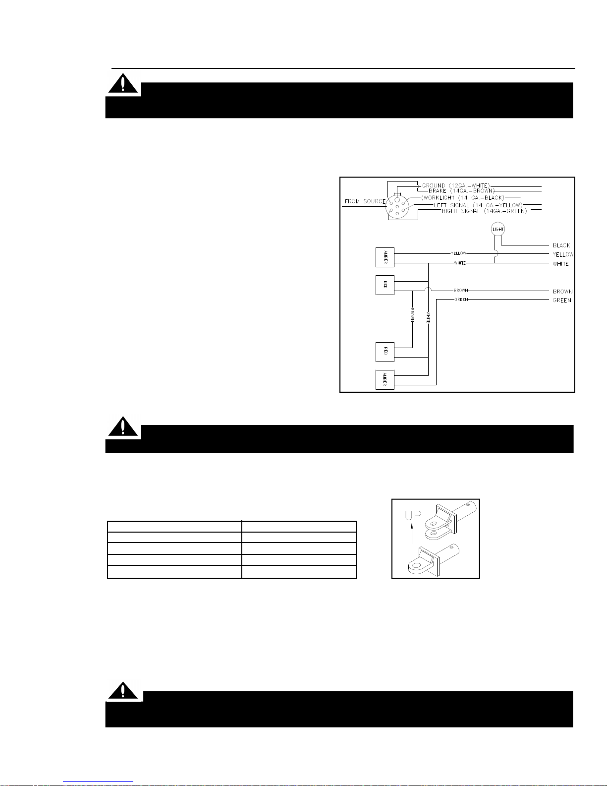
The following schematic complies with ANSI/
ASAE Standard S279.9/SAEJ137 for new production tractors. NOTE: Wiring specifications
may be different for older tractor models.
Consult your tractor operator’s manual or dealer
for proper wiring and installation. (Fig. 1)
Fig. 1
OM02482
TRACTOR HOOK-UP
Make certain that you can see the driver and the driver can see you at all times to avoid
being struck by tractor while attempting to hook up the Cart.
--Make sure sufficient counterweight is used on the tractor’s front-end.
--Move draw bar into shortest position.
Selecting the proper hitch pin size for your tractor!
Tractor Size
Category 4 (250-400 H.P.)
Category 3 (110-250 H.P.)
Category 2 (65-110 H.P.)
Category 1 (Under 65 H.P.)
Information gathered from: ISO/TC2/SC2 N4123
--With cart hitched to tractor, hook up P.T.O. (see pg. 9-C), following all safety precautions.
--Hook up 7-point electrical plug connection to tractor.
--Be sure hitch is positioned as shown. Gusset should be to top.
Hitch Pin Diameter
2”
1-1/2”
1-1/4”
1”
OM02548
HYDRAULIC HOOK-UP
CAUTION! When coupling hyd. hoses to ports on tractor, be sure that coupler ends are
clean of dust, dirt and debris. Failure to do so could contaminate hydraulic system resulting in
excessive wear and possible failure.
-- Properly identify the hoses for the auger fold and the flow control operation.

8
-- It is advisable to use the hydraulic control lever closest to the operator (most commonly known
as control lever No. 1) to activate the flow control.
-- Once everything has been hooked up, test for any possible needed adjustments:
-Are tires inflated to proper pressure?
-Do Augers run smoothly?
-Does Dump Auger fully extend?
-Does P.T.O. operate properly?
-Is Slip Clutch set too loose or too tight?
-Do Flow Control Gates operate properly?
-Is Indicator Arm working properly?
-Are all lights working properly?
If any one of these is not adjusted properly please read the SERVICE section outlined in the
manual or contact your nearest KILLBROS dealer for further information.
With everything in good operating condition, be sure to close flow control gates before use.
OPERATION IN FIELD
The Grain Cart is not insulated. Keep away form all electrical lines and devices. Electro-
cution can occur without direct contact.
1. Make sure the flow control door is in the closed position before loading into the cart.
2. Engage PTO at a low RPM; and open flow control gate.
3. Increase speed to approximately 850 RPM for optimum unloading performance.
4. Use the flow control opening to slow the rate of the flow rather than the tractor’s RPM.
NOTE: If overload causes the clutch to slip (standard PTO drive) or motor to stall (hydraulic drive),
stop auger immediately. Excessive heating of the clutch will require replacement of internal parts.
Close flow control door and relieve auger unloaded pressure by opening bottom pit dump door to
remove some grain from auger.
5. Do not disengage the auger with the flow control open. Excessive start-up torque may result,
putting stress on the cart driveline and your tractor.
6. Properly identify the tractor remotes for proper hook-up of the flow control and auger fold. A
mix-up can damage the auger drive system.
7. Under any circumstance, DO NOT enter the cart with the auger or tractor running.
8. It is strongly advised that the unloaded auger always be returned to the transport position when
not in use.
Operating the PTO
When finishing operation of PTO driven equipment, shift PTO control to neutral, shut off
the engine and wait until the PTO stops before getting off the tractor and disconnecting
the equipment.
Do not wear loose clothing when operating
the power take-off, or when near rotating equipment.
speed for the particular equipment in use.
PTO drive shafts must only be used for their
intended purpose.
PTO drive shafts, clutches and freewheels are
designed for specific machine types and power
requirements. They must not be replaced by
other models.
To avoid injury do not clean, adjust, unclog,
or service PTO driven equipment when the
tractor engine is running.
Never exceed the recommended operating
NOTE: See the tractor and implement manufacturers’ operating instructions.
Ensure that the PTO shaft is securely connected.
9
B1
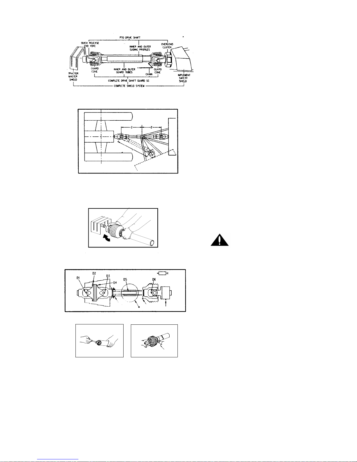
A. Only use a completely shielded drive sys-
tem:
PTO drive systems with complete shielding,
include the tractor master shield and implement shielding installed all the time. If any
component of the shield system has been
removed for any reason it, or an identical
replacement part, must be installed before
operation.
B. Maximum Joint Angles:
1. Joint (Standard Type)
Continuous operation - 25 degrees
Short duration - 45 degrees
Stationary - 90 degrees
Check shaft articulation and clearance zone!
Joint articulations of more than 45 degrees
lead to damage. Contact between PTO drive
shaft and tractor or implement (e.g. three point
hitch, drawbar) lead to damage.
C. Coupling the PTO drive shaft (Fig. C1)
Twist Lock
1. Twist locking collar and simultaneously
push PTO drive shaft onto PTO shaft until
the locking device engages.
D2
C1
D3
D1
Check to insure all the locks are secure before engaging the PTO drive shaft.
D. Lubrication (Fig. D1-D3)
Lubricate with quality grease before starting
work every 8 operating hours. Clean and
grease PTO drive shaft before each prolonged
period of non-use.
Molded nipples on the shield near each shield
bearing are intended as grease fittings and
should be lubricated every 8 hours of operation. Telescoping members must be lubricated
to operate successfully regardless of whether
a grease fitting is provided for that purpose.
Telescoping members without fittings should
be pulled apart and grease should be applied
manually. Check and grease guard tubes in
winter to prevent freezing.
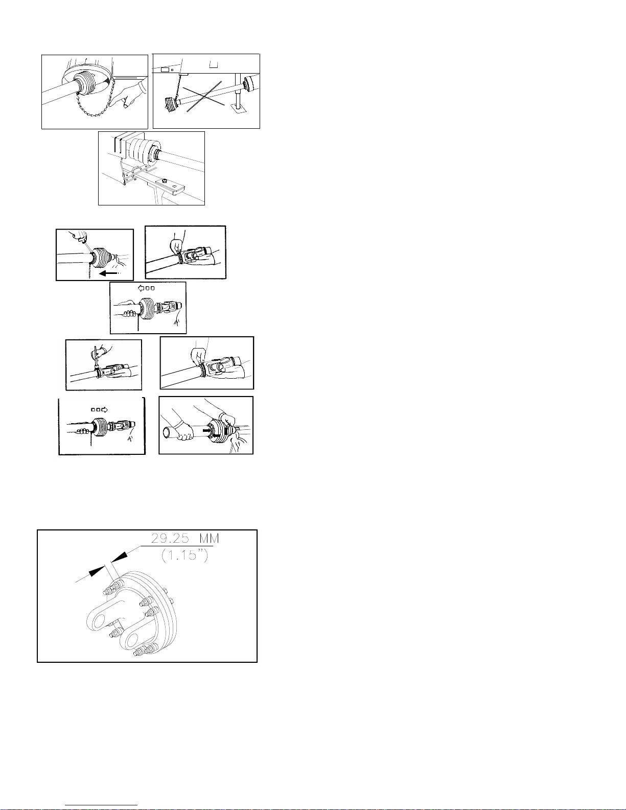
E. Chains (Fig. F1-F3)
NOTE: The chain is intended to prevent the
shield from rotating against non-moving parts,
thereby preventing shield damage. A properly
installed chain will increase the service life of
the shield.
10
E1 E2
E3
F1
F2
1. Chains must be fitted to allow sufficient
articulation of the shaft in all working positions. Care must be taken to be sure
that chain does not become entangled with
drawbar hitch or other restrictions during
operation or transport of machine.
2. The PTO drive shaft must not be suspended from the chain when PTO is not
in use or unattached from drive unit.
3. If chain should become unattached, do
not attempt to reattach it with the PTO
engaged. Turn off PTO and tractor engine
before making any repairs. If chain is
missing, replace it before use.
F. Dismantling guard:
1. Keep cone pressed downward and release
collar tabs by pushing with a screwdriver.
Push cone off tube.
2. Spread collar to remove from tube.
G1
G3
F3
G2
G4
OM02520
3. Slide tube off the shaft.
G. Assembling guard:
1. Grease collar groove and inner profile tube.
2. Fit shield tube into collar by centering the
slots over the collar teeth.
3. Align cone, centering grease nipple to
grease filling hole on collar. Press downward to connect.
4. Make sure the three collar tabs are properly engaged by tapping on cone.
H. Slip Clutch - preset at factory
Damage may occur to other parts of the grain
cart if the spring tension is not set properly.
Correct operating procedure of the slip clutch
is to have it slip slightly with each use.
1. If adjustment is necessary, length from
flange surface to under side of nut should
be 29.25 MM (1.15”).
2. Tighten nuts following an alternating cross
pattern until reaching the height specified.
Check that height is constant for all
springs.
3. If too much slippage occurs, only tighten
each nut a quarter of a turn at a time.
This quarter turn will increase the torque
approximately 500-750 inch lbs.
4. After extended time without use, the slip
clutch may “freeze up”. It is very important at the beginning of each season to
loosen the nuts, slip the clutch, and retighten the nuts to the correct length.

11
PLEASE READ THE
FOLLOWING INFORMATION
BEFORE USING YOUR SCALE!
THE FOLLOWING STEPS MUST BE CONSIDERED WHEN USING YOUR SCALE AND TO REALIZE ITS BEST PERFORMANCE. DIGI-STAR SCALES ARE MANUFACTURED TO PROVIDE 1/2%
MAXIMUM ERROR. A GOOD INSTALLATION AND PROPER USE ARE REQUIRED IN ORDER TO
OBTAIN ADVERTISED ACCURACY.
A GOOD INSTALLATION REQUIRES THAT ALL LOAD CELLS ARE PROPERLY INSTALLED WITH
“TOP” ACCURATELY POSITIONED.
OPERATION
TO INSURE + OR -1/2% MAXIMUM ERROR, THE UNIT MUST BE USED AS A STATIONARY
LOAD-OUT WEIGH HOPPER FROM BIN TO TRUCK, FOR EXAMPLE, THE GROUND MUST BE
SMOOTH AND LEVEL WITH MAXIMUM 5” SLOP PER 10 FEET.
TO INSURE + OR -1% MAXIMUM ERROR, THE UNIT MUST BE USED SO THAT ALL WEIGHT
MEASUREMENTS OCCUR ON FLAT SMOOTH GROUND (MAXIMUM OUT OF LEVEL 10” IN 10
FEET) IDEALLY, ALL WEIGHT MEASUREMENTS FOR A FIELD WOULD OCCUR IN THE SAME
SPOT.
WARNING!
ALWAYS DISCONNECT CABLES
FROM SCALE INDICATOR BEFORE
JUMP STARTING ENGINE.
 Loading...