

Page 1
C1D1 FLOOD – INTRODUCTION & LOGIC
LED
FEATURES-SPECIFICATIONS
Applications
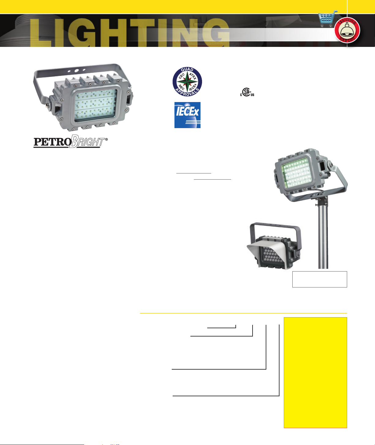
LED KF1L Series Explosion-proof Floods are
designed for installations where moisture,
dirt, dust, corrosion and vibration may be
present, or NEMA 3 and 4X areas where
wind, water, snow or high ambients can be
expected. They can be used in locations
made hazardous by the presence of
flammable vapors or gases or combustible
dusts as defined by the NEC.
Typical applications include manufacturing
plants, and certain chemical and
petrochemical processing facilities, sewage
treatment plants, off-shore and dockside
installations, garages and storage facilities
Compliances
• UL-8750 for LED lighting
• ANSI/UL 1598A
• UL-844 Standard for lighting fixtures for
hazardous locations, Class I, Division 1;
Class II, Division 1; Class III
• CSA C22.2 no. 137-M1981 electric
luminairies for use in hazardous locations
• IEX or IEX4B suffix for Zone 1 and Zone
21 to IEC 60079-0,60079-1,60079-31,
60079-7 Standards
• Enclosed and gasketed
• NEMA 3, 4X
• IP66
Materials
• Body, end caps and lens frame corrosion
resistant copper-free aluminum alloy with
baked powder epoxy/polyester finish,
electrostatically applied for complete,
uniform corrosion protection
• All external hardware - stainless steel
• Thermal shock and impact resistant extra
heavy-duty glass lens
• High temperature silicone gasketing
• Trunnion heavy gauge 316 SS
LED Flood Features and Standards
• Factory Sealed Construction
• One 3/4” NPT & one M20 entry standard (see
logic for other choices)
• Supplemental surge protection (AC models
120-277VAC only) and looping terminals are
standard
• Crisp White Light for Excellent Color Rendering
– Chromaticity 5000 K (CCT); approx. 70 CRI
• Energy Savings – High lumens per watt
• Long Life – 100,000+ maintenance free hours
to 70% initial lumens
• Instant On – Including after power interruption
• World Voltage 120 – 277VAC 50/60Hz
• Solder-LESS LED Board Connections –
Vibration Resistant
• LM80-08* Measurement of lumen
maintenance for LED light sources
• LM79-08* Certified “Absolute” Photometry,
including Chromaticity Color for Solid State
Lighting
• L70 Values – Industry Nomenclature for
Hours of use to 70% of initial Lumens – TM21* & calculated
Catalog Number Logic
KF1L - Series Constant
Fixture Wattage
150
165
195
- 150W
- 165W
- 195W
090
- 90W
105
- 105W
110
- 110W
125
- 125W
Voltage
30
- 120 - 277VAC 50/60Hz
33
- 347 - 48 0VAC 60Hz (90W-125W)
34
- 120 -250VDC (9 0W-125W)
Options
IEX4B -
Four bolt termination cover (see Note 1)
LT -
For -50°C to +55°C, IEC Zone 1 (see Note 1)
F -
Single Fuse
FF -
Double Fusek
D20 -
Dual M-20 Entries
D25 -
Dual M-25 Entries
D75 -
Dual 3/4” NPT
KF1L 125 30 XX
KILLARK LIGHTING
G
G
I
I
L
L
KF1L SERIES
Class I, Div. 1&2, Groups B,C,D
Class I, Zone 1&2, Groups IIB+H2, IIA
Class II, Div. 1&2, Groups EFG, Class III
Enclosure Type 4X, IP66 (-50°C to +55°C)
File LR11713
IEC Ex Rated model (w/IEX or IEX4B suffix) Zone 1, Zone 21
Ex de IIB+H2 T6..T5, Gb, IP66
Tamb -20°C ≤Ta≤ +55°C; Option LT for -50°C ≤Ta≤ +55°Cj
Ex de IIB T6..T5, Gb, -50°C ≤Ta≤ +55°Cj
Ex tb IIIC T90°C Db, -50°C ≤Ta≤ +55°Cj
Certificate IECE X CSA 14.0010
ATEX Certificate SIRA14ATEX1159X
Patent Pending
Fixture Design
KF1L with KFS-6
Sliptter mount
on 2” pipe
Dark Sky Visor
KF1L-DARK
* LM-xx & TM-xx are illumination Engineering Society
Standards designed to promote uniformity in testing
procedures among test labs and manufacturers. For
more information go to www.ies.org
k Fusing not for Canadian or Marine Installations
Suitable for Paint
Spray
jConstruction/Certication
Notes: KF1L units are standard
with one 3/4” NPT hub & one
M20 hub – both plugged,
with an 8-bolt factory sealed
termination chamber, suitable
for CID1 BCD -50 °C to +55°C
and IEC Zone 1
Ex de suitable for -20°C to
55°C.
Use option LT for models
needing IEC Zone 1, -50°C
to +55°C suitability for
hydrogen.
Option IEX4B utilizes 4
terminal cover bolts for Ex de
and maintains all ratings
EXCEP T CID1 BCD.
See logic for other entry
options
H
H
A
A
T
T
I
I
H
H
N
N
G
G
C
C
O
O
Z
Z
L
L
Page 2
KILLARK LIGHTING
T
T
I
I
H
H
N
N
G
G
G
G
I
I
L
L
H
H
A
A
Z
Z
KF1L SERIES
C
C
O
O
L
L
C1D1 FLOOD – ORDERING & TECHNICAL DATA
ORDERING INFORMATION AND AMBIENT SUITABILITY C1D1 C2D1 IEC ZONE 1 IEC ZONE 21 L70
CATALOG NO. WEIGHT LBS./KG WATTS VOLTAGE AMPS LUMENS 40°C 55°C 40°C 55°C 40°C 55°C 40°C 55°C TM-21 CALCULATED
KF1L09030
KF1L09034 120-250VDC 0.72-0.28
KF1L10530
KF1L10534 120-250VDC 0.85-0.33
KF 1L11030
46.00 / 20.87
KF 1L11034 120-250VDC 0.95-0.37
KF 1L125 30
KF 1L125 33 347-480VAC 0.38-0.28
KF1L12534 120-250VDC 1.10- 0.4 3
KF 1L150 30 150 120-277VAC 1.25-0.54 13 28 0 T5 - - - - T5 - - 60300 190000
KF 1L165 30 165 120 -277VAC 1.38-0.60 13760 T5 - - - - T5 - - 72600 278000
KF 1L195 30 195 120-277VAC 1.63-0.70 15707 T5 - - - - T5 - - 72600 278000
j Yellow highlighted models have extra high lumen LED’s.
k See logic for 347-480V availability
l Amperage measured at 120VAC; 277VAC calculated
m Use minimum 75° Supply Wire @4 0°C Ambient; 9 0°@ 55°C Ambient
n CID1 40°/55° & C2D1 4 0°C use Aiming Figure “A” below.
120-27 7VAC 0.72-0.31
90
120-27 7VAC 0.85-0.37
105
120-27 7VAC 0.95-0.41
110
120-27 7VAC 1.10- 0.4 8
125
7182 T6 T6 (EFG)
8362 T6 T6 (EFG)
1059 0 T6 T6 (EFG)
1159 0 T6 T6 (EFG)
o 55°C C2D1 EFG T3C Aiming Figure “B”, 55° C2D1 EF T3A Aiming Figure “A”
p First number is lens temperature under 25mm layer of dust; Second number is lens
temp for dust cloud.
** TM-21 based values require very long duration testing. IES TM-21 “official reported”
is based on at 8,00 0 to 10,000 hours of LED chip manufacturer’s LM -80 Testing at
printing.
T6 T5 160-75 175-9 0 60100 270000KF1L09033 347-480VAC 0.25-0.18
o
T6 T5 160-76 175-91 60100 270000KF1L10533 347-480VAC 0.29-0.21
o
T6 T5 160-77 175-9 2 72600 278000KF1L11033 347-480VAC 0.33-0.24
o
T6 T5 160-78 175-9 3 72600 278000
o
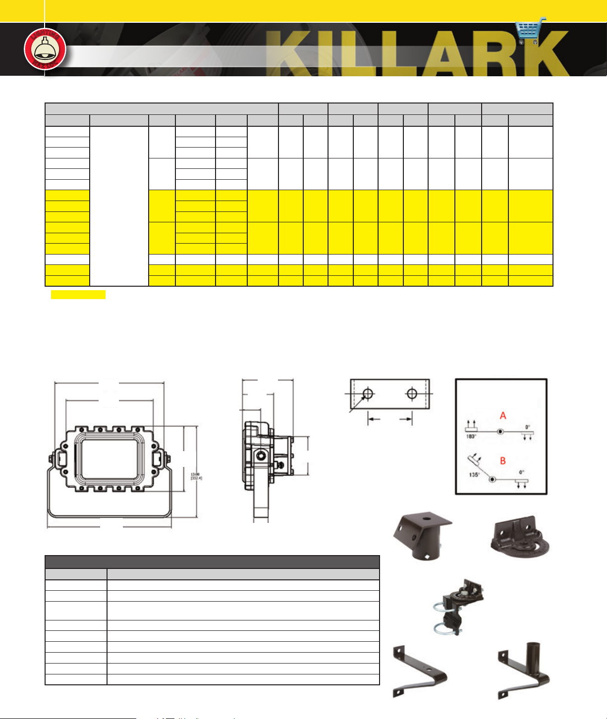
Dimensions
15.65
[397.4]
12.50
[317.5]
2.52
[64.0]
4.27
[108.5]
6.91
[175.5]
.531 DIA.
(13)
Trunnion Mounting
5.30
[134.7]
17.75
[450.9]
Front
9.36
[237.7]
Side
2.00
[50.8]
KFL MOUNTS AND ACCESSORIESj
CATALOG NUMBER DESCRIPTION
KFS-6 Steel Slipfi tter for 2” Pipe (2-3/8” o.d.) Tenon. Slips 3.75” Over Pipe.
KFCB Heav y Dut y Cast-Iron Crossarm F itting for Horizont al Trunnion
KFWB Heav y Duty Wall Mount and/or Pipe Clamp Fitting Clamps 2” Pipe (2-3/8” o.d.) Through
K4040 Heav y Dut y Steel Wall Bracket. (Must be with
4041 Heav y Dut y Steel Wall Bracket 2” Pipe (2-3/8” o.d.) Tenon Fitting.
KFLG Wire Guard, 316 Stainless S teel
VMSC10
KF1L-DA RK
KF1L-DOOR Replacement Door and Lens Assembly
j Fittings available to adapt trunnion mount oodlights to crossarms, poles and walls. Must be ordered separately.
k Drop limit 1’. Attaches to luminaire cable provision and to mounting structure.
l Designed to eliminate uplight when aimed at 45°.
2-1/2” Pipe (2-7/8” o.d.)
10’ Stainless Steel Safety Cable with loop gripk
Dark Sk y Visor, White Painted Aluminuml
KFCB
Crossarm Fitting).
3-1/8”
(79)
Detail
Wall Bracket
KFS-6
Sliptter
Wall/Pipe Bracket
K4040
Aiming Figures
See Notes n & o
KFWB
KFCB
Cross Arm Mount
4041
Tenon Fitting
 Loading...