

Page 1
KILLARK CONTROLS
R
R
T
T
O
O
N
N
L
L
S
O
S
O
C
C
H
H
A
A
Z
Z
C
C
O
O
L
L
G SERIES
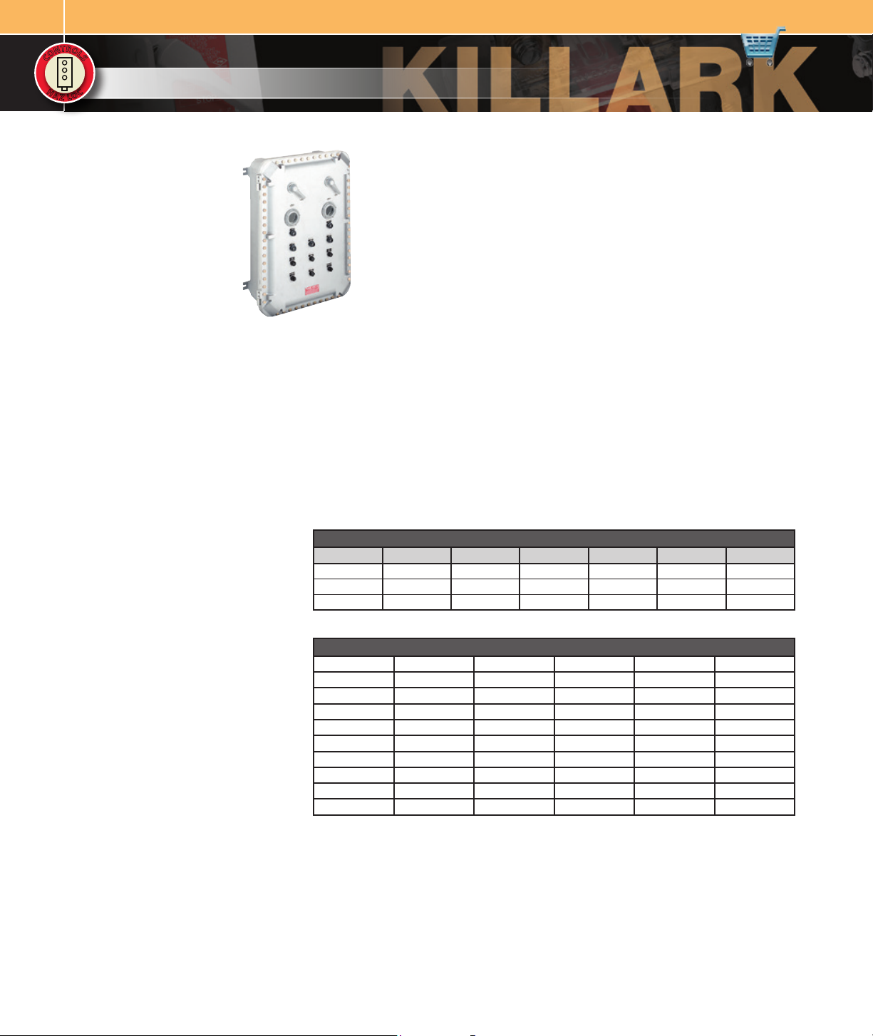
CUSTOM CONTROL PANEL OPERATORS INTRODUCTION
FEATURES-SPECIFICATIONS
Applications
G Series custom control panel operators
are designed for use in hazardous locations
when installed in suitable enclosures such
as B7E EXB, XJB, DB, SWB and GCS Series
boxes and B7, Y7 Starter Enclosures.
Features
• Operators are all aluminum except for
certain movable parts which are stainless
steel, all other parts such as screws are
either stainless steel or plated steel
• Threaded bodies are all 3/4”-14 NPSM
thread
• Control stations can be grouped into a
single assembly thus reducing installation
time and cost
• Junction boxes may be used to mount
operators along with glass lens for
viewing internally mounted meters.
Additional relays, timers, terminal blocks,
or other equipment may also be internally
mounted to provide a single centralized
control unit.
• Custom operators other than standard
assemblies listed may be ordered by
proper catalog number from custom
operator ordering system pages C72 &
C73
Electrical Rating
Push button stations, selector switches
Heavy duty 600 VAC max.
Pilot lights 120 VAC.
Dimensions
See Dimensional information for G Series
operators on page C74.
Class I, Div. 1 & 2, Groups B, C, D
Class I, Zones 1 & 2, Groups llB, llA
Class II, Div. 1 & 2, Groups E, F, G
Class Ill
NEMA 3, 4, 4X, 7 (B, C, D) 9 (E, F, G)
See Area Classification Chart below
Recommended Operator Selection
Short Style
DB/SWB/GCS Enclosures. Assemblies with
wall thickness up to 1/2” thick.
Long Style
All B7E/XJB Enclosures. EXB (see page E35)
enclosures with cover thickness up to 1-1/2”
thick.
Extended Style
EXB larger size enclosures (see page E35)
with cover thickness up to 2-1/2” thick.
Killark long and extended push buttons,
selector switches, reset and potentiometer
operators are CENELEC/ATEX EExd IIB+H2
when installed in series EXB*CEN and
GR*CEN enclosures.
For pilot lights and illuminated push buttons
in CENELEC/ATEX applications see page C65.
CONTACT BLOCK RATINGS – A600/P600
CURRENT 120 VAC 240 VAC 480 VAC 600 VAC 125 VDC 250 VDC
INRUSH 60 30 15 12 .55 .27
BREAKING 6 3 1.5 1.2 .55 .27
CARRYING 10 10 10 10 2.55 2.55
Note: Contact blocks can be stacked four deep maximum.
AREA CLASSIFICATION CHART FOR OPERATORS
GO1m GO17k GO30k GO57k GOL2m GOL38l
GO2m GO18k GO34k GO58k GOL3m GOL39l
GO5m GO19k GO35k GO36l GO59k GOL4m GOL113l
GO6m GO21k GO37l GO113l GOL5m GOL114l
GO7m GO22k GO38l GO114l GOL6m GOLRSTm
GO8l GO23k GO39l GO133k GOL7m GOL8l GOM1n
GO10m GO25k GO40j GO13 4k GOL14m GOR11m
GO14m GO26k GO50k GOB3m GOL15 m GORSTm
GO15m GO27k G051k GOB4m GOL36l GO11388k
GO16k GO28k GO56k GOL1m GOL37m GO11372k
jClass II Div. 1 & 2 Group EFG NEMA 9EFG
kClass I Div. 1 & 2 Group CD, Class II Div. 1 & 2 Group EFG, Class III NEMA 7CD, 9EFG
lClass I Div. 1 & 2 Group BCD, Class II Div. 1 & 2 Group EFG, Class III NEMA 3, 4, 7BCD, 9EFG
mClass I Div. 1 & 2 Group BCD, Class II Div. 1 & 2 Group EFG, Class III NEMA 3, 4, 4X, 7BCD, 9EFG
nClass I Div. 1 & 2 Group CD, Class II Div. 1 & 2 Group EFG, Class III NEMA 3, 4, 7CD, 9EFG
Page 2
KILLARK CONTROLS
G SERIES
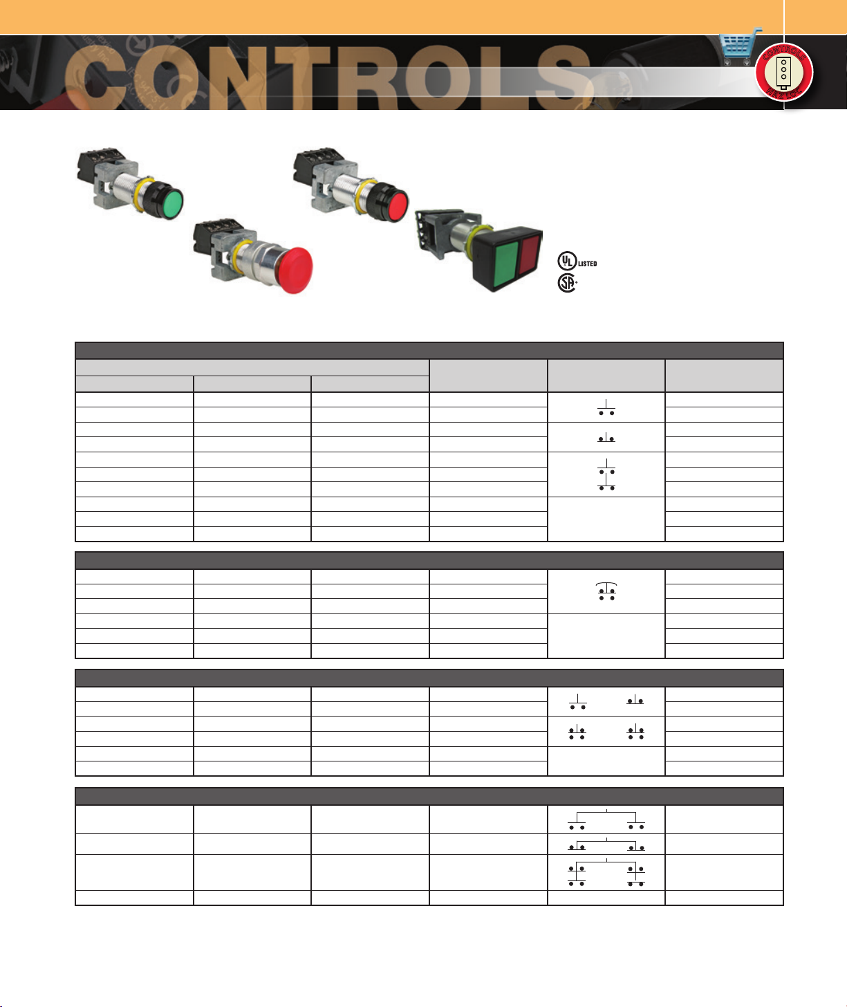
PUSH BUTTONS
Class I, Div. 1 & 2, Groups B, C, Dm
Class I, Zones 1 & 2, Groups llB, llA
Class II, Div. 1 & 2, Groups E, F, G
Class Ill
NEMA 3, 4, 4X, 7 (B, C, D) 9 (E, F, G)
Push Button Green Push Button Red
Mushroom Push Button
Double Push Button
FEATURES-SPECIFICATIONS
G SINGLE PUSH BUTTON (MOMENTARY CONTACT)
CATALOG NUMBERj
SHORTm
GO21-GZ 1B GO1-GX1B N34 GOL1G1 GREEN START OR STOP
GO21-KZ1C GO1-KX1C N34 GOL1K1 BLACK RESET OR BLANK
GO21-RZ2B GO1-RX2B N34 GOL1R 2 RED
GO21-KZ2C GO1-KX2C N34 GOL1K 2 BLACK RESET OR BLANK
GO21-GZ3C GO1-GX3C N34 GOL1G3 GREEN
GO21-RZ3C GO1-RX3C N34 GOL1R 3 RED RESET OR BLANK
GO21-KZ 3C GO1-KX3C N34 GOL1K3 BLACK RESET OR BL ANK
GO21-GZ0C GO1-GX0C N34 GOL1G GREEN
GO21-RZ0C GO1-RX0C N34 GOL1R RED RESET OR BLANK
GO21-KZ 0C GO1-KX0C N34 GOL1K BLACK RESET OR BLANK
LONG EXTENDED
COLOR
See Area Classification Chart
page C62 for Details
- File E12379
Certified - File LR11714
See files for details or call Killark.
CONTACT TYPEl NAMEPLATE MARKINGk
NONE
START OR STOP
RESET OR BLANK
RESET OR BLANK
R
R
T
T
O
O
N
N
L
L
S
O
S
O
C
C
H
H
C
C
A
A
O
O
Z
Z
L
L
G SINGLE PUSH BUTTON (MAINTAINED CONTACT) MUSHROOM HEAD PUSH – PULL OPERATION
GOM21-GM3C GOM1-GM3C N3 4 GO ML1G3 GREEN BLANK
GOM21-RM3C GOM1-RM3C N34 GOM L1R3 RED BLANK
GOM21-KM3C GOM1-KM3C N34 GO ML1K3 BLACK BLANK
GOM21-GM0C GOM1-GM0C N34 GOML1G GREEN
GOM21-RM0C GOM1-RM0C N34 GOML1R RED BLANK
NONE
BLANK
GOM21-KM0C GOM1-KM0C N34 GOML1K BLACK BL ANK
G DOUBLE PUSH BUTTON (MOMENTARY CONTACT)
GO22-GR12D G02-GR12D N34 GOL2GR12 GREEN/RED START/STOP OR BL ANK
GO22-KK12D G02-KK12D N3 4 GOL2KK12 BLACK/BLACK START/STOP OR BL ANK
GO22-GR33D G02-GR33D N34 GOL2GR33 GREEN/RED
START/STOP OR BL ANK
GO22-KK33D G02-KK33D N34 GOL2KK33 BLACK /BLACK START/STOP OR BLANK
GO22-GR00D G02-GR00D N34 GOL2GR GREEN/RED
GO22-KK00D G02-KK00D N34 GOL2KK BLACK/BLACK START/STOP OR BLANK
NONE
START/STOP OR BL ANK
G DOUBLE PUSH BUTTON (MAINTAINED CONTACT)n
— GOR11-GR6D N34 — GREEN/RED START/STOP OR BLANK
— GOR11-GR7D N34 — GREEN/RED START/STOP OR BL ANK
— GOR11-GR8D N34 — GREEN/RED START/STOP OR BLA NK
— GOR11-GR0D N34 — GREEN/RED NONE START/STOP OR BLANK
jRefer to catalog page C62 to select proper operator for enclosure, pages C70 & C71 for accessories, page C62 for complete details on Area Classication of operators,
page C74 for Dimensional information.
kNameplates are double sided.
lContact Blocks are shown in their normal position.
mShort style operators are suitable for Class l Group C & D, Class ll Group E,F,G only.
nWhen pressed, the green button will remain in a depressed position. Pressing red button releases green from the depressed position.
Page 3
KILLARK CONTROLS
R
R
T
T
O
O
N
N
L
L
S
O
S
O
C
C
H
H
A
A
Z
Z
G SERIES
C
C
O
O
L
L
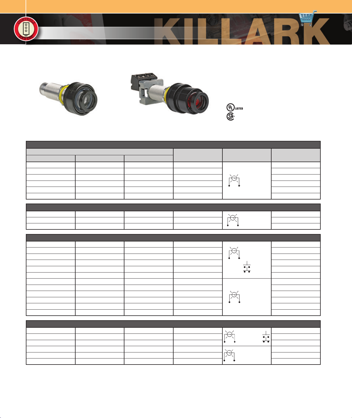
Pilot Light Illuminated Button
FEATURES-SPECIFICATIONS
CATALOG NUMBERj
SHORTm
GO23-A23C GOB3-A2 3C N34 GOL3A AMBER
GO23-B23C GOB3-B23C N34 GOL3B BLUE BLANK
GO23-C23C GOB3-C23C N34 GOL3C CLEAR BLANK
GO23-F23C GOB3-F23C N34 GOL3F FROSTED BLANK
GO23-G23C GOB3-G23C N34 GOL3G GREEN BLANK
GO23-R23C GOB3-R23C N34 GOL3R RED BLANK
PILOT LIGHTS
LONG EXTENDED
G PILOT LIGHTS
COLOR
Class I, Div. 1 & 2, Groups B, C, Dm
Class I, Zones 1 & 2, Groups llB, llA
Class II, Div. 1 & 2, Groups E, F, G
Class Ill
NEMA 3, 4, 4X, 7 (B, C, D) 9 (E, F, G)
See Area Classification Chart
page C62 for Details
- File E12379
Certified - File LR11714
See files for details or call Killark.
CONTACT TYPEl NAMEPLATE MARKINGk
BLANK
110-1 20 VOL TS
FULL VOLTS
G PILOT LIGHTS WITH LED 110 VOLT LAMPS
— GOB3-A23C N34 LED GOL3A LED AMBER
— GOB3-G23C N34 LED GOL3G LED GREEN BLANK
— GOB3-R23C N34 LED GOL3R LED RED BLANK
110-120 VOLTS FULL
VOLTS (LED)
BLANK
G ILLUMINATED BUTTON OR PUSH TO TEST PILOT LIGHT
— GOB4-A233C N34 GOL4A3 AMBER
— GOB4-B233C N34 GOL4B3 BLUE BLANK
— GOB4-C233C N34 GOL4C3 CLEAR BLANK
110-120 VOLTS
FULL VOLTS
— GOB4-F233C N34 GOL4F3 FROSTED BLANK
— GOB4-G23 3C N34 GOL4G3 GREEN BLANK
— GOB4-R233C N34 GOL4R3 RED BLANK
— GOB4-A230C N34 GOL4A AMBER
— GOB4-B230C N34 GOL4B BLUE BLANK
— GOB4-C230C N34 GOL4C CLEAR BLANK
— GOB4-F230C N34 GOL4F FROSTED BLANK
110-1 20 VOL TS
NO CONTA CT
BLOCKS
— GOB4-G230C N34 GOL4G GREEN BLANK
— GOB4-R230C N34 GOL4R RED BLANK
BLANK
BLANK
G ILLUMINATED BUTTON OR PUSH TO TEST PILOT LIGHT WITH LED 110 VOLT LAMPS
— GOB4-A233C N34 LED GOL4A 3 LED AMBER
— GOB4-G233C N3 4 LED GOL4G3 LED GREEN BLANK
110-1 20 VOL TS
FULL VOLTS (LED)
— GOB4-R233C N3 4 LED GOL4R3 LED RED BLANK
— GOB4-A230C N34 LED GOL4A LED AMBER
— GOB4-G230C N34 LED GOL4G LED GREEN BLANK
110-120 VOLTS (LED)
NO CONTA CT BLOCKS
— GOB4-R230C N34 LED GOL4R LED RED BLANK
jRefer to catalog page C62 to select proper operator for enclosure, pages C70 & C71 for accessories, page C62 for complete details on Area Classication of operators,
page C74 for Dimensional information.
kNameplates are double sided.
lContact Blocks are shown in their normal position.
mShort style operators are suitable for Class l Group C & D, Class ll Group E, F, G only.
BLANK
BLANK
Page 4

KILLARK CONTROLS
PILOT LIGHTS FOR ATEX / CENELEC APPLICATIONS
Class I, Div. 1 & 2, Groups B, C, D
Class I, Zones 1 & 2, Groups llB+H2, llA
Class II, Div. 1 & 2, Groups E, F, G
Class Ill
NEMA 3, 4, 4X, 7 (B, C, D) 9 (E, F, G)
ATEX-EExd IIB + H2
- File E12379
Certified - File LR11714
G SERIES
R
R
T
T
O
O
N
N
L
L
S
O
S
O
C
C
H
H
C
C
A
A
O
O
Z
Z
L
L
Pilot Light ATEX Illuminated Push Button ATEX
PTB No. 03ATE X 1203 U
FEATURES-SPECIFICATIONS
G PILOT LIGHTS
CATALOG NUMBERj
LONG EXTENDED
GOB3-A2 3C N34CN GOL3ACN AMBER
GOB3-B23C N34CN GOL3BCN BLUE BLANK
GOB3-C23C N34CN GOL3CCN CLEAR BLANK
GOB3-F23C N34CN GOL3FCN FROSTED BLANK
GOB3-G23C N34CN GOL3GCN GREEN BLANK
GOB3-R23C N34CN GOL3RCN RED BLANK
COLOR
CONTACT TYPEl NAME PLATE MARKINGk
BLANK
110-120 VOLTS
FULL VOLTS
G PILOT LIGHTS WITH LED 110 VOLT LAMPS
GOB3-A23C N34LEDCN GOL3ALEDCN AMBER
GOB3-G23C N34LEDCN GOL3GLEDCN GREEN BLANK
110-120 VOLTS FULL
VOLTS (LED)
GOB3-R23C N34LEDCN GOL3RLEDCN RED BLANK
BLANK
G ILLUMINATED PUSH BUTTON OR PUSH TO TEST PILOT LIGHT
GOB4-A233CN34CN GOL4A3CN AMBER
GOB4-B233CN34CN GOL4B3CN BLUE BLANK
GOB4-C233CN34CN GOL4C3CN CLEAR BLANK
110-120 VOLTS
FULL VOLTS
GOB4-F233CN34CN GOL4F3CN FROSTED BLANK
GOB4-G233CN34CN GOL4G3CN GREEN BLANK
GOB4-R233CN34CN GOL4R3CN RED BLANK
GOB4-A230CN34CN GOL4A0CN AMBER
GOB4-B230CN34CN GOL4B0CN BLUE BLANK
GOB4-C230CN34CN GOL4C0CN CLEAR BLANK
GOB4-F230CN34CN GOL4F0CN FROSTED BLANK
110-1 20 VOL TS
NO CONTA CT
BLOCKS
GOB4-G230CN34CN GOL4G0CN GREEN BLANK
GOB4-R230CN34CN GOL4R0CN RED BLANK
BLANK
BLANK
G ILLUMINATED PUSH BUTTON OR PUSH TO TEST PILOT LIGHT WITH LED 110 VOLT LAMPS
GOB4-A233CN34LEDCN GOL4A3LEDCN AMBER
GOB4-G233CN34LEDCN GOL4G3LEDCN GREEN BLANK
110-120 VOLTS FULL
VOLTS (LED)
GOB4-R233CN34LEDCN GOL4R3LEDCN RED BLANK
GOB4-A230CN34LEDCN GOL4A0LEDCN AMBER
GOB4-G230CN34LEDCN GOL4G0LEDCN GREEN BLANK
110-120 VOLTS (LED) NO
CONTACT BLOCKS
GOB4-R230CN34LEDCN GOL4R0LEDCN RED BLANK
j Refer to catalog page C62 to select proper operator for enclosure, pages C70 & C71 for accessories, page C62 for complete details on Area Classi cation of operators, page
C74 for Dimensional information.
k Nameplates are double sided.
l Contact Blocks are shown in their normal position.
BLANK
BLANK
NOTE: British standards BSEN50014 and EN50018 have special marking and relamping demands that require
modications to the standard Killark Pilot Lights. Pilots lights and illuminated push buttons on this page
must be used for enclosures that are modied to meet ATEX/CENELEC.
Page 5

KILLARK CONTROLS
R
R
T
T
O
O
N
N
L
L
S
O
S
O
C
C
H
H
A
A
Z
Z
C
C
O
O
L
L
G SERIES
SELECTOR SWITCHES
Class I, Div. 1 & 2, Groups B, C, Dm
Class I, Zones 1 & 2, Groups llB, llA
Class II, Div. 1 & 2, Groups E, F, G
Class Ill
NEMA 3, 4, 4X, 7 (B, C, D) 9 (E, F, G)
See Area Classification Chart
page C62 for Details
Selector Switch
- File E12379
Certified - File LR11714
FEATURES-SPECIFICATIONS
See files for details or call Killark.
G SELECTOR SWITCH MAINTAINED CONTACT
CATALOG NUMBERj
SHORTm
G025-2A3F G05-2A3F N34 G0L52A3
G025-3C3G G05-3C3G N34 G0L53C3
G025-4H8H G05-4H8H N34 G0L54H8
LONG EXTENDED
CONTACT ARRANGEMENTl TYPE OF OPERATIONk
LEFT RIGHT
LEFT RIGH TCENTER
1 2 3 4
G SELECTOR SWITCH MAINTAINED CONTACT WITHOUT CONTACTS
G025-2A0F G05-2A0F N34 G0L52A NONE TWO POSITION
G025-3C0G G05-3C0G N34 G0L53C NONE THREE POSITION
G025-4H0H G05-4H0H N34 G0L54H NONE FOUR POSITION
G SELECTOR SWITCH SPRING RETURN
G026-3F G06-3F N34 G0L63
G027-6G G07-6G N34 G0L76
G034-6G G014-6G N34 G0 L14 6
G035-6G G015-6G N34 G0 L15 6
LEFT RIGHT
LEFT RIGHTCENTER
LEFT RIGHTCENTER
LEFT RIGHTCENTER
TWO POSITION SPRING RETURN TO LEFT
THREE POSITION SPRING RETURN TO
CENTER FROM RIGHT OR LEFT
THREE POSITION SPRING RETURN TO
CENTER FROM RIGHT, MAINTAIN IN LEFT
THREE POSITION SPRING RETURN TO
CENTER FROM LEFT, MAINTAIN IN RIGHT
TWO POSITION
THREE POSITION
FOUR POSITION
1 N.O./1 N.C
2 N.O.
2 N.O.
2 N.O.
G SELECTOR SWITCH SPRING RETURN WITHOUT CONTACTS
G026-0F G06-0F N34 G0L6 NONE TWO POSITION SPRING RETURN TO LEFT
G027-0G G07-0G N34 G0L7 NONE
G034-0G G014-0G N34 G0L14 NONE
G035-0G G015-0G N34 G0L15 NONE
jRefer to catalog page C62 to select proper operator for enclosure, C70 & C71 for Accessories, C 62 for complete details on Area Classication of operators, C74 for
Dimensional Information, C72 for Special Contact Congurations.
kNameplates are Double sided. 2 position marked OFF-ON and Blank on other side. 3 position marked HAND- OFF-AUTO and Blank on other side. 4 position is Blank.
lContact Blocks are shown in their normal position.
mShort style operators are suitable for Class I Group C & D, Class II Group E,F,G only.
THREE POSITION SPRING RETURN TO
CENTER FROM RIGHT OR LEFT
THREE POSITION SPRING RETURN TO
CENTER FROM RIGHT, MAINTAIN IN LEFT
THREE POSITION SPRING RETURN TO
CENTER FROM LEFT, MAINTAIN IN RIGHT
Page 6

KEYED SELECTOR SWITCHES
KILLARK CONTROLS
G SERIES
Class I, Div. 1 & 2, Groups B, C, Do
Class I, Zones 1 & 2, Groups llB, llA
Class II, Div. 1 & 2, Groups E, F, G
Class Ill
NEMA 3, 4, 4X, 7 (B, C, D) 9 (E, F, G)
See Area Classification Chart
page C62 for Details
R
R
T
T
O
O
N
N
L
L
S
O
S
O
C
C
H
H
C
C
A
A
O
O
Z
Z
L
L
Key Operated
Selector Switch
- File E12379
Certified - File LR11714
See files for details or call Killark.
FEATURES-SPECIFICATIONS
G KEY SELECTOR SWITCH MAINTAINED CONTACTm
CATALOG NUMBERj
SHORTo
G028-2A3F22D G08-2A3F22D N34 G0L82A322D
G028-3C3G32D G08-3C3G32D N34 G0L83C332D
LONG EXTENDED
CONTACT ARRANGEMENTl TYPE OF OPERATIONkn
LEFT RIGHT
LEFT RIGHTCENTER
THREE POSITION
G KEY SELECTOR SWITCH MAINTAINED CONTACT WITHOUT CONTACTSm
G028-2A0F22D G08-2A0F22D N34 G0L82A022D NONE TWO POSITION
G028-3C0G32D G08-3C0G32D N34 G0L83C032D NONE THREE POSITION
G KEY SELECTOR SWITCH SPRING RETURNm
G056-2L3F22D G036-2L3F22D N34 G0L36L322D
G057-3C6G32D G037-3C6G32D N34 G0L37C632D
G058-3L6G32D G038-3L6G32D N34 G0L38L632D
G059-3R6G32D G039-3R6G32D N34 G0L39R632D
LEFT RIGHT
LEFT RIGHTCENTER
LEFT RIGHTCENTER
LEFT RIGHTCENTER
TWO POSITION SPRING RETURN TO LEFT
THREE POSITION SPRING RETURN TO
CENTER FROM RIGHT OR LEFT
THREE POSITION SPRING RETURN TO
CENTER FROM RIGHT, MAINTAIN IN LEFT
THREE POSITION SPRING RETURN TO
CENTER FROM LEFT, MAINTAIN IN RIGHT
TWO POSITION
1 N.O./1 N.C.
2 N.O.
2 N.O.
2 N.O.
G KEY SELECTOR SWITCH SPRING RETURN WITHOUT CONTACTSm
G056-2L0F22D G036-2L0F22D N34 G0L36L022D NONE TWO POSITION SPRING RETURN TO LEF T
G057-3C0G32D G037-3C0G32D N34 G0L37C032D NONE
G058-3L0G32D G038-3LOG32D N34 G0L38L032D NONE
GO59-3R0G32D G039-3R0G32D N34 G0L39R032D NONE
j Refer to catalog page C62 to select proper operator for enclosure, pages C70 & C71 for Accessories, page C62 for complete details on Area Classication of operators, page
C74 for Dimensional Information, page C72 for Special Contact Congurations.
k Nameplates are Double sided. 2 position marked OFF-ON and Blank on other side. 3 position marked HAND -OFF-AUTO and Blank on other side. 4 position is Blank.
l Contact Blocks are shown in their normal position.
m All Key Operators are furnished Keyed Different If Keyed Alike is required substitute letter “A” for letter “D” in catalog number.
n Keys are removable in Lef t position on 2 position selectors and in Center position on 3 position selectors. For key removal in ALL positions change “22” in 2 position to “20”
and “32” in 3 position to “30”.
o Short style operators are suitable for Class I Group C & D, Class II Group E,F,G only.
THREE POSITION SPRING RETURN TO
CENTER FROM RIGHT OR LEFT
THREE POSITION SPRING RETURN TO
CENTER FROM RIGHT, MAINTAIN IN LEFT
THREE POSITION SPRING RETURN TO
CENTER FROM LEFT, MAINTAIN IN RIGHT
Page 7

KILLARK CONTROLS
R
R
T
T
O
O
N
N
L
L
S
O
S
O
C
C
H
H
A
A
Z
Z
C
C
O
O
L
L
G SERIES
SPECIALTY OPERATORS
Class I, Div. 1 & 2, Groups B, C, Dm
Class I, Zones 1 & 2, Groups llB, llA
Class II, Div. 1 & 2, Groups E, F, G
Class Ill
NEMA 3, 4, 4X, 7 (B, C, D) 9 (E, F, G)
See Area Classification Chart
page C62 for Details
Certified - File LR11714
See files for details or call Killark.
Snap Switch
Multi Turn Single Turn
Potentiometer and Rheostat
(electrical device not included)
FEATURES-SPECIFICATIONS
G SNAP SWITCH OPERATOR
CATALOG NUMBERj
SHORTm
GO3 0-31F GO10 -31F N34
GO30-33F GO10-33F N34
(UL File E10501)
LONG 125 VAC 250 VAC
TYPE
SWITCH
SPST
SPDT
(3-W AY)
10 AMP 5 AMP
10 AMP 10 AMP
G POTENTIOMETERS AND RHEOSTATS OPERATOR
CATALOG NUMBERj
SHORTm
GO133 GO113 N34 GOL113 SINGLE TURN
GO134 GO114 N34 GOL114
(UL File E150827)
LONG EXTENDED
TYPE
TWENTY
TURN
G RESET OPERATOR
CATALOG NUMBERj
SHORTm
GO40-KX2C GO-RST GOLRST
(UL File E150827)
LONG EXTENDED
NAMEPLATEk TYPE OPERATIONj
RESET OR
BLANK
RATINGS
NAMEPLATE
MARKINGk
OFF/ON OR
OFF/ON OR
DESCRIPTIONj
Control operator for use
with potentiometers or
rheostats having a 1/4”
diameter by 7/8” long
shaft.
Black plunger t ype reset
operator, supplied with
a 6” long fiber extension
which c an be removed or
cut to desired length.
Capillary SealRotary or Motor Shaft
BLANK
BLANK
Reset
G ROTARY OR MOTOR SHAFT OPERATOR
CATALOG
NUMBERj
GO-16n
GO-18n
GO-17n
GO-19n
GO-51
SHAFT
DIAMETER
1/4”
3/8”
1/4”
3/8”
1/2”
TYPE
MALE-FEMALE
MALE-MALE
DESCRIPTIONj
Rotary or motor shaf t
operator used to transfer
rotary motion through
wall of explosion proof
enclosure.
G CAPILLARY SEALS
CATALOG
NUMBERj
GO-11388-078n
GO-11372-0 93n
j Refer to catalog page C62 to select proper operator for enclosure, pages C70
& C71 for Accessories, page C62 for complete details on Area Classication of
operators, page C74 for Dimensional Information.
Nameplates are double sided.
k
l GO40 series reset button is suitable for Class II E, F, and G locations only.
m Short style operators are suitable for Class I Group C & D, Class II Group E,F,G
only.
n These devices are not UL or CSA approved.
CAPILLARY
SIZE
0.078±
.002 DIA.
0.093±
.002 DIA.
TYPE
ACCEP TS
CAPILLARY
WITH MAX.
BULB DIA. OF
9/ 16”.
DESCRIPTIONj
Use where a mechanical
means for passing a
thermostat or similar
capillary tube through
the wall of a haz ardous
location enclosure.
 Loading...