

Page 1
KILLARK FITTINGS
D
N
I
N
I
T
T
G
G
T
T
I
S
I
S
F
F
S
S
T
T
D
DURALOY® 8 SERIES
C
C
O
O
L
L
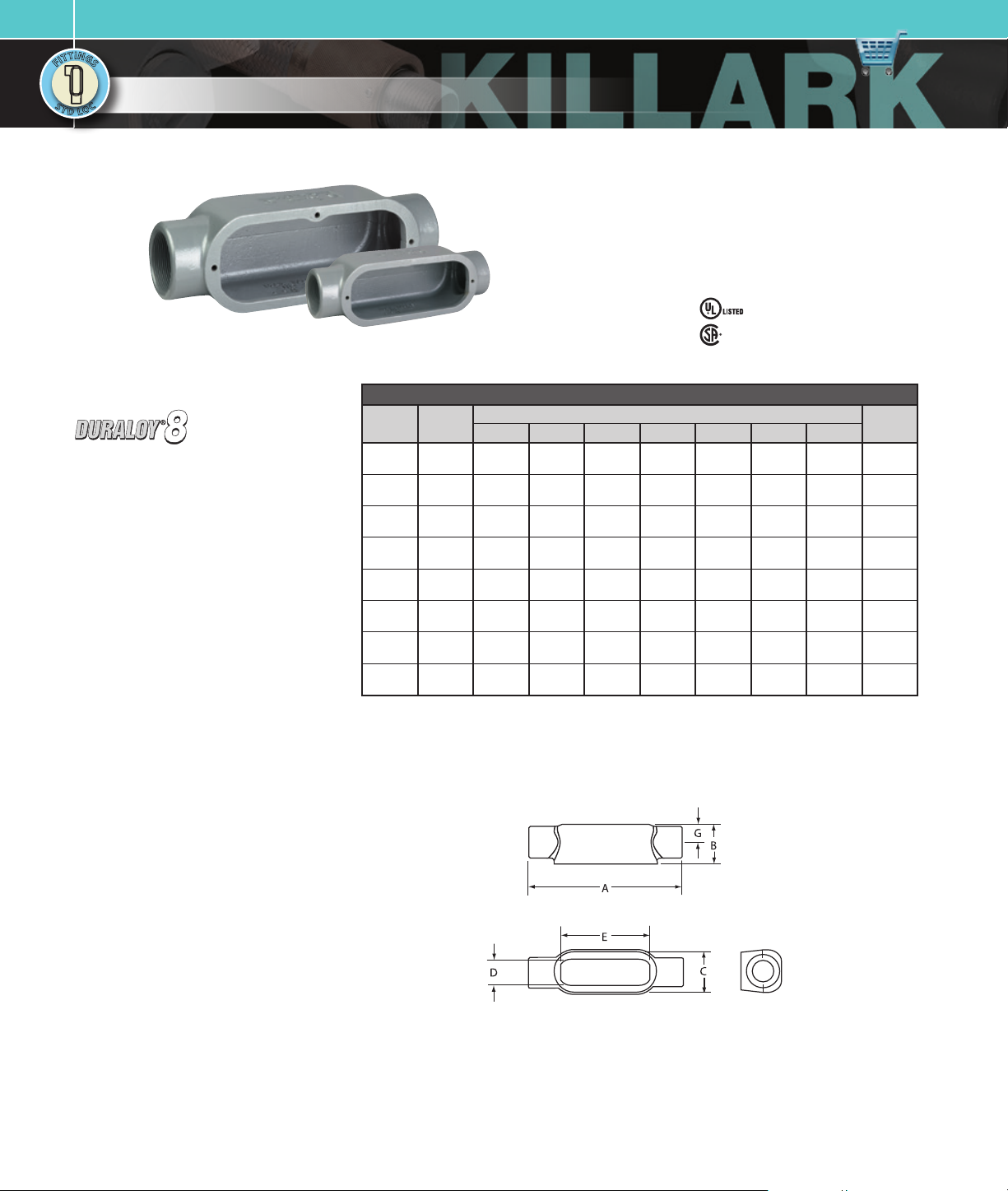
IRON CONDUIT BODIES
• Suitable for wet locations when used
with gasketed covers.
• Federal Specification
W-C-586D/A-A 50563.
• Suitable for use in hazardous location
applications when installed according to
NEC Articles 50 1.10(b), Class I, Div. 2,
(Suitable for use in Class I Zone 2
applications) 502.10 and 503.10.
File No. E3397
C Ty pe
Certified File No. LR11852
FEATURES-SPECIFICATIONS
Applications
To provide access to conductors for pulling,
splicing, and maintenance. Threaded for
rigid conduit and IMC.
Features
• Completely interchangeable with
competative bodies, gaskets, and covers
• Flat back design provides greater cubic
capacity for easier wire pulling and more
room for splicing
• Raintight when used with gasketed covers
• Stainless steel screws on stamped and
cast covers
• Smooth integral wire bushings
Material/Finish
Duraloy Gray Iron Alloy
• Tri-coat finish of electrozinc, chromate
sealant, and electrostatically applied
powder coating.
C TYPE CONDUIT BODY*
1-15 /32 ”
(37)
1-21/32”
(42)
1-27/32”
(47)
2-5/32”
(55)
2-25/32”
(71)
3-27/32”
(98)
5”
(127 )
5”
(127 )
DIMENSIONS
1”
(25)
1-3/16”
(30)
1-3/8”
(35)
1-3/4”
(44)
2-3/32”
(53)
3”
(76)
4-1/4”
(108)
4-1/4”
(108)
3-9/ 32”
(83)
3-15/16”
(100)
4-17/3 2”
(115)
5-15/16”
(151)
6-1 /2”
(165)
8-5/8”
(219)
10-7/8”
(276)
10-7/8”
(276)
—
—
—
—
—
—
—
—
CATALOG
NUMBER
HUB SIZE
C18 1/2”
C28 3/4”
C38 1”
C448 1-1/4”
C58 1-1/ 2”
C68 2”
C78 2-1/2 ”
C88 3”
A B C D E F G
5-5/16”
6-9/16”
7-9 /16”
8-7/ 16”
10-3/8 ”
12-3 /8 ”
15-5/8”
15-5/8”
(135)
(167)
(192)
(214)
(264)
(314)
(397)
(397)
1-15 /32 ”
(37)
1-11/ 16”
(43)
1-31/32 ”
(50)
2-3/8”
(60)
2-25/32”
(71)
3-9/16”
(90)
4-7/ 16”
(113)
4-13/16”
(122)
* For conduit body packaged with cover and gasket, add CG to the catalog number.
Dimensions
5/8”
(16)
3/4”
(19)
7/8”
(22)
1-3/32”
(28)
1-3/8”
(35)
1-7/8 ”
(48)
2-1/2 ”
(64)
2-1/2 ”
(64)
VOLUME
CU. IN.
5.0
8.0
12.25
23.25
42.50
105.00
200.00
21 7.00
C Type
Page 2
D
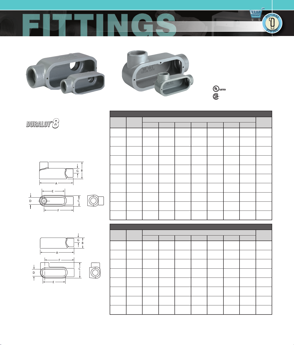
LB Typ e
IRON CONDUIT BODIES
LL Typ e
KILLARK FITTINGS
DURALOY® 8 SERIES
• Suitable for wet locations when used
with gasketed covers.
• Federal Specification
W-C-586D/A-A 50563.
• Suitable for use in hazardous location
applications when installed according to
NEC Articles 50 1.10(b), Class I, Div. 2,
(Suitable for use in Class I Zone 2
applications) 502.10 and 503.10.
File No. E3397
Certified File No. LR11852
N
I
N
I
T
T
G
G
T
T
I
S
I
S
F
F
S
S
C
C
T
T
O
D
O
L
L
FEATURES-SPECIFICATIONS
See page F10 for Standard Materials & Finish
Dimensions
LB Type
LL Type
LB TYPE CONDUIT BODY*
1-15 /32 ”
(37)
1-21/32”
(42)
1-27/32”
(47)
2-5/32”
(55)
4-25/ 32”
(121)
4-13/16”
(122)
6-1 /8”
(156)
6-1 /2”
(165)
7-9 /16”
(192)
7-13/16”
(198)
DIMENSIONS
1”
(25)
1-3/16”
(30)
1-3/8”
(35)
1-3/4”
(44)
2-3/32”
(53)
3”
(76)
4-1/4”
(108)
4-1/4”
(108)
5-7/ 16”
(138)
5-7/ 16”
(138)
3-9/ 32”
(83)
3-15/16”
(100)
4-17/3 2”
(115)
5-15/16”
(151)
6-1 /2”
(165)
8-5/8”
(219)
10-7/8”
(276)
10-7/8”
(276)
13-7/8”
(352)
13-7/8”
(352)
4-3/8”
(111)
4-29/ 32”
(125)
5-23/ 32”
(145)
6-13/ 32”
(163)
7-3 /4”
(197)
9-3/16”
(233)
11-7/16”
(29 1)
11-7/16”
(29 1)
13-3/4”
(349)
13-3/4”
(349)
CATALOG
NUMBER
HUB SIZE
LB18 1/2”
LB28 3/4”
LB38 1”
LB448 1-1/4”
LB58 1-1/ 2”
LB68 2”
LB78 2-1/ 2”
LB888 3”
LB98 3-1/2”
LB108 4”
A B C D E F G
5-3/ 32”
(129)
5-3/4”
(146)
6-5/8”
(168)
7-1/ 2”
(191)
9-1 /8”
(232)
11-1/ 8”
(283)
13-15/16”
(354)
13-15/16”
(354)
16-7/8”
(429)
16-7/8”
(429)
2-9/32”
(58)
2-1/2 ”
(64)
2-29/32”
(74)
3-5/16”
(84)
4-1/32 ”
(102)
4-13/16”
(122)
6-1 /8”
(156)
6-1 /2”
(165)
7-9 /16”
(192)
7-13/16”
(198)
LL TYPE CONDUIT BODY*
1-15 /32 ”
(37)
1-21/32”
(42)
1-27/32”
(47)
2-5/32”
(55)
4-25/ 32”
(121)
4-13/16”
(122)
6-1 /8”
(156)
6-1 /2”
(165)
DIMENSIONS
1”
(25)
1-3/16”
(30)
1-3/8”
(35)
1-3/4”
(44)
2-3/32”
(53)
3”
(76)
4-1/4”
(108)
4-1/4”
(108)
3-9/ 32”
(83)
3-15/16”
(100)
4-17/3 2”
(115)
5-15/16”
(151)
6-1 /2”
(165)
8-5/8”
(219)
10-7/8”
(276)
10-7/8”
(276)
4-3/8”
(111)
4-29/ 32”
(125)
5-23/ 32”
(145)
6-13/ 32”
(163)
7-3 /4”
(197)
9-3/16”
(233)
11-7/16”
(29 1)
11-7/16”
(29 1)
CATALOG
NUMBER
HUB SIZE
LL18 1/2”
LL28 3/4”
LL38 1”
LL448 1-1/4”
LL58 1-1/2 ”
LL68 2”
LL78 2-1/2 ”
LL888 3”
A B C D E F G
5-3/ 32”
(129)
5-3/4”
(146)
6-5/8”
(168)
7-1/ 2”
(191)
9-1 /8”
(232)
11-1/ 8”
(283)
13-15/16”
(354)
13-15/16”
(354)
2-9/32”
(56)
2-1/2 ”
(64)
2-29/32”
(74)
3-5/16”
(84)
4-1/32 ”
(102)
4-13/16”
(122)
6-1 /8”
(156)
6-1 /2”
(165)
* For conduit body packaged with cover and gasket, add CG to the catalog number.
5/8”
(16)
3/4”
(19)
7/8”
(22)
1-3/32”
(28)
1-3/8”
(35)
1-7/8 ”
(48)
2-1/2 ”
(64)
2-1/2 ”
(64)
3-1/8 ”
(79)
3-1/8 ”
(79)
5/8”
(16)
3/4”
(19)
7/8”
(22)
1-3/32”
(28)
1-3/8”
(35)
1-7/8 ”
(48)
2-1/2 ”
(64)
2-1/2 ”
(64)
VOLUME
CU. IN.
5.0
8.0
13.0
24.0
42.0
105.0
200.0
21 7.0
380.0
400.0
VOLUME
CU. IN.
5.0
8.0
13.0
24.0
42.0
105.0
200.0
21 7.0
Page 3

KILLARK FITTINGS
D
N
I
N
I
T
T
G
G
T
T
I
S
I
S
F
F
S
S
T
T
D
DURALOY® 8 SERIES
C
C
O
O
L
L
IRON CONDUIT BODIES
• Suitable for wet locations when used
with gasketed covers.
• Federal Specification
W-C-586D/A-A 50563.
• Suitable for use in hazardous location
applications when installed according to
NEC Articles 50 1.10(b), Class I, Div. 2,
(Suitable for use in Class I Zone 2
applications) 502.10 and 503.10.
File No. E3397
LR Typ e
T Ty pe
Certified File No. LR11852
FEATURES-SPECIFICATIONS
See page F10 for Standard Materials & Finish
Dimensions
LR Type
T Type
LR TYPE CONDUIT BODY*
2-9/32”
(58)
2-1/2 ”
(64)
2-29/32”
(74)
3-5/16”
(84)
4-1/32 ”
(102)
4-13/16”
(122)
6-1 /8”
(156)
6-1 /2”
(165)
DIMENSIONS
1”
(52)
1-3/16”
(30)
1-3/8”
(35)
1-3/4”
(44)
2-3/32”
(53)
3”
(76)
4-1/4”
(108)
4-1/4”
(108)
3-9/ 32”
(83)
3-15/16”
(84)
4-17/3 2”
(115)
5-15/16”
(151)
6-1 /2”
(165)
8-5/8”
(219)
10-7/8”
(276)
10-7/8”
(276)
4-3/8”
(111)
4-29/ 32”
(125)
5-23/ 32”
(145)
6-13/ 32”
(163)
7-3 /4”
(199)
9-3/16”
(233)
11-7/16”
(29 1)
11-7/16”
(29 1)
CATALOG
NUMBER
HUB SIZE
LR18 1/ 2”
LR28 3/4”
LR38 1”
LR448 1-1/4 ”
LR58 1-1/ 2”
LR68 2”
LR78 2-1/ 2”
LR888 3”
A B C D E F G
5-3/ 32”
5-3/4”
6-5/8”
7-1/ 2”
9-1 /8”
11-1/ 8”
13-15/16”
13-15/16”
(129)
(146)
(168)
(191)
(232)
(283)
(354)
(354)
1-15/16”
(49)
1-11/ 16”
(43)
1-31/32 ”
(50)
2-3/8”
(60)
2-25/32”
(71)
3-9/16”
(90)
4-7/ 16”
(113)
4-13/16”
(122)
T TYPE CONDUIT BODY*
2-5/16”
(59)
2-1/2 ”
(64)
2-25/32”
(71)
3-1/8 ”
(79)
4-1/32 ”
(102)
5-1/8 ”
(130)
6-11 /16”
(170)
6-11 /16”
(170)
DIMENSIONS
1”
(25)
1-3/16”
(30)
1-3/8”
(35)
1-3/4”
(44)
2-3/32”
(53)
3”
(76)
4-1/4”
(108)
4-1/4”
(108)
3-9/ 32”
(83)
3-15/16”
(100)
4-17/3 2”
(115)
5-5/16”
(135)
6-1 /2”
(165)
8-5/8”
(219)
10-11/ 16”
(271)
10-11/ 16”
(271)
—
—
—
—
—
—
—
—
CATALOG
NUMBER
HUB SIZE
T18 1/2”
T28 3/4”
T38 1”
T448 1-1/ 4”
T58 1-1/2 ”
T68 2”
T78 2-1/2”
T88 3”
A B C D E F G
5-15/16”
6-9/16”
7-9 /16”
8-7/ 16”
10-3/8 ”
12-3 /8 ”
15-5/8”
15-5/8”
(151)
(167)
(192)
(214)
(264)
(314)
(397)
(397)
1-25/32”
(45)
2”
(51)
2-9/32”
(58)
2-5/8”
(67)
2-25/32”
(71)
3-9/16”
(90)
4-7/ 16”
(113)
4-13/16”
(122)
* For conduit body packaged with cover and gasket, add CG to the catalog number.
5/8”
(16)
3/4”
(19)
7/8”
(22)
1-3/32”
(28)
1-3/8”
(35)
1-7/8 ”
(48)
2-1/2 ”
(64)
2-1/2 ”
(64)
5/8”
(16)
3/4”
(19)
7/8”
(22)
1-3/32”
(28)
1-3/8”
(35)
1-7/8 ”
(48)
2-1/2 ”
(64)
2-1/2 ”
(64)
VOLUME
CU. IN.
5.0
8.0
13.0
24.0
42.0
105.0
200.0
21 7.0
VOLUME
CU. IN.
6.0
10.0
15.0
25.0
44.0
105.0
200.0
21 7.0
Page 4

D
TB Typ e
IRON CONDUIT BODIES
X Ty pe
KILLARK FITTINGS
DURALOY® 8 SERIES
• Suitable for wet locations when used
with gasketed covers.
• Federal Specification
W-C-586D/A-A 50563.
• Suitable for use in hazardous location
applications when installed according to
NEC Articles 50 1.10(b), Class I, Div. 2,
(Suitable for use in Class I Zone 2
applications) 502.10 and 503.10.
File No. E3397
Certified File No. LR11852
N
I
N
I
T
T
G
G
T
T
I
S
I
S
F
F
S
S
C
C
T
T
O
D
O
L
L
FEATURES-SPECIFICATIONS
See page F10 for Standard Materials & Finish
Dimensions
TB Type
TB TYPE CONDUIT BODY*
1-15/16”
(49)
1-21/32”
(42)
1-27/32”
(47)
2-3/16”
(55)
2-25/32”
(71)
3-7/ 8”
(98)
DIMENSIONS
1”
(25)
1-3/16”
(30)
1-3/8”
(35)
1-3/4”
(44)
2-3/32”
(53)
3”
(76)
3-9/ 32”
(83)
3-15/16”
(100)
4-17/3 2”
(115)
5-5/16”
(135)
6-1 /2”
(165)
8-5/8”
(219)
—
—
—
—
—
—
CATALOG
NUMBER
HUB SIZE
TB18 1/2”
TB28 3/4”
TB38 1”
TB448 1-1/4 ”
TB58 1-1/ 2”
TB68 2”
A B C D E F G
5-15/16”
6-9/16”
7-9 /16”
8-7/ 16”
10-3/8 ”
12-3 /8 ”
(151)
(167)
(192)
(214)
(264)
(314)
2-15/16”
(75)
2-1/2 ”
(64)
2-25/32”
(71)
3-1/8 ”
(79)
4-1/32 ”
(102)
5-1/8 ”
(130)
X TYPE CONDUIT BODY*
3-1/8 ”
(79)
3-15/16”
(100)
3-23/ 32”
(94)
4-1/16”
(103)
5-9/ 32”
(134)
6-3/8”
(162)
DIMENSIONS
1”
(25)
1-3/16”
(30)
1-3/8”
(35)
1-3/4”
(44)
2-3/32”
(53)
3”
(76)
3-9/ 32”
(83)
3-15/16”
(100)
4-17/3 2”
(115)
5-5/16”
(135)
6-1 /2”
(165)
8-5/8”
(219)
—
—
—
—
—
—
CATALOG
NUMBER
HUB SIZE
X18 1/2”
X28 3/4”
X38 1”
X448 1-1/4”
X58 1-1/ 2”
X68 2”
A B C D E F G
5-15/16”
6-9/16”
7-9 /16”
8-7/ 16”
10-3/8 ”
12-3 /8 ”
(151)
(167)
(192)
(214)
(264)
(314)
1-25/32”
(45)
2”
(51)
2-9/32”
(58)
2-5/8”
(67)
2-25/32”
(71)
3-9/16”
(90)
* For conduit body packaged with cover and gasket, add CG to the catalog number.
5/8”
(16)
3/4”
(19)
7/8”
(22)
1-3/32”
(26)
1-3/8”
(35)
1-7/8 ”
(48)
5/8”
(16)
3/4”
(19)
7/8”
(22)
1-3/32”
(26)
1-3/8”
(35)
1-7/8 ”
(48)
VOLUME
CU. IN.
6.0
10.0
15.0
25.0
44.0
105.0
VOLUME
CU. IN.
6.0
10.0
15.0
25.0
44.0
105.0
X Type
Page 5

KILLARK FITTINGS
D
N
I
N
I
T
T
G
G
T
T
I
S
I
S
F
F
S
S
T
T
D
DURALOY® 8 SERIES
C
C
O
O
L
L
IRON COVERS AND GASKETS
• Suitable for wet locations when used
with gasketed covers.
• Federal Specification
W-C-586D/A-A 50563.
• Suitable for use in hazardous location
applications when installed according to
NEC Articles 50 1.10(b), Class I, Div. 2,
Stamped Steel CoversCast Covers
Cover Gaskets (Neoprene)
(Suitable for use in Class I Zone 2
applications) 502.10 and 503.10.
File No. E3397
Certified File No. LR11852
FEATURES-SPECIFICATIONS
See page F10 for Standard Materials & Finish
Cast Material/Finish
Duraloy Gray Iron Alloy
• Tri-coat finish of electrozinc, chromate
sealant, and electrostatically applied
powder coating
• 300 Series stainless steel screws
Galvanized Steel
• Natural finish
• 300 Series stainless steel screws
CAST IRON COVERS
CATALOG NUMBER HUB SIZE
180F 1/2” 4-7/ 32”(107) 1-15/ 32”( 37 ) 3/8”(10)
280F 3/4” 4-13/16”(122) 1-21/32”(42) 3 /8 ”(10)
380F 1” 5-19/ 32”( 142) 1-27/32 ”(47) 5/8”(16)
480F 1-1/4” 6-9/16”(167) 2-3/16”(56) 5/8”(16)
580F 1-1/2” 7-7/8”(2 00) 2-25/32”(71) 5/8”(16)
680F 2” 9-3 /4”(24 8) 3-7/ 8”(98) 5/8”(16)
880F 2-1/ 2” 12-1/4”(311) 5”(127) 5 /8”(16)
880F 3” 12-1/4”(311) 5”(12 7) 5/8”(16)
980F 3-1/ 2” 15”(381) 6-1/4”(159) 5/8”(16)
980F 4” 15”(381) 6-1/4”(15 9) 5/8”(16)
LENGTH WIDTH HEIGHT
OVERALL DIMENSIONS
STAMPED STEEL COVERS
CATALOG NUMBER HUB SIZE
180S 1/2” 4-7/32 ”(10 7) 1-15 /32 ”(37 ) 5/16”(8)
280S 3/4” 4-13/16”(122) 1-21/32”(42) 5/16”(8)
380S 1” 5-19 /32 ”(142 ) 1-2 7/32”(47 ) 5/16”(8)
480S 1-1/4 ” 6-9/16”(167) 2- 3/16”(5 6) 5/16”(8)
580S 1-1/2 ” 7-7/8 ”(200) 2-25/32”(71) 5/16”(8)
680S 2” 9-3/4”(248) 3-7/8 ”(9 8) 5/16”(8)
880S 2-1/2” 12-1/4”(311) 5”(127) 9/ 16”(14)
880S 3” 12-1/4”(311) 5”(127) 9/16”(14)
980S 3-1/2” 15”(381) 6-1/4”( 159) 9/16”(14)
980S 4” 15”(381) 6-1/4”(159) 9/16”(14)
LENGTH WIDTH HEIGHT
OVERALL DIMENSIONS
Material/Finish
• Neoprene. Compression molded.
COVER GASKETS
CATALOG NUMBER HUB SIZE
GASK8 51N 1/2” 4-7/32”(107 ) 1-15/3 2”(3 7) 1/8”(3)
GASK852N 3/4” 4-13/16”(122) 1-21/32”(42) 1/8”(3)
GASK853N 1” 5-19/ 32”( 142) 1-27/32 ”(47) 1/8”(3)
GASK854N 1-1/4” 6-9/ 16”(167) 2-3/16”(56) 1/8”(3)
GASK805N 1-1/ 2” 7-7/ 8”(200) 2-25/32”(71) 1/8”(3)
GASK806N 2” 9-3/4”(248) 3-7/8”(98) 1/8”(3)
GASK808N 2-1/ 2” 12-1/4”(311) 5”(127) 1/8”(3)
GASK808N 3” 12-1/4”(311) 5”(127) 1/8”(3)
GASK809N 3-1/2” 15”(38 1) 6-1/ 4”(15 9) 1/8”(3)
GASK809N 4” 15”(3 81) 6-1 /4”(159) 1/8”(3)
NOTE - (2) screws 1/2” through 1-1/4”, (4) screws 1-1/2” through 4”
LENGTH WIDTH HEIGHT
OVERALL DIMENSIONS
 Loading...