

Page 1
D
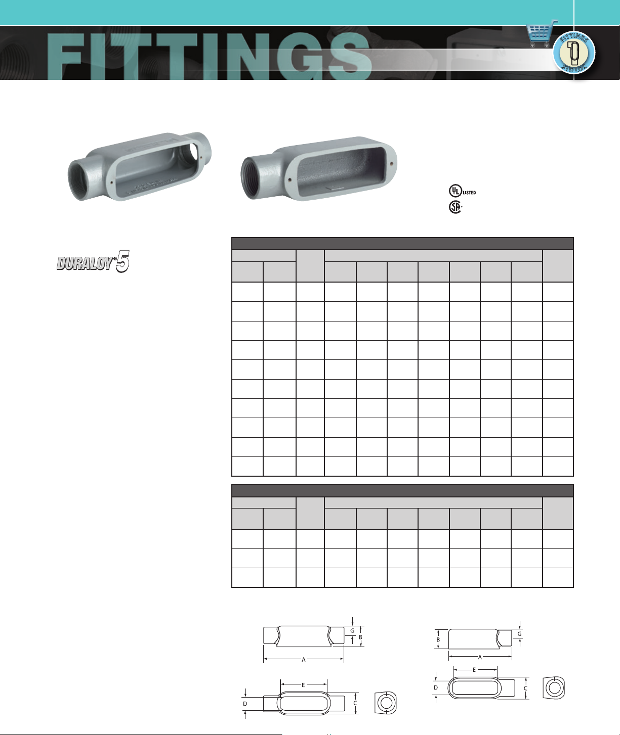
O SERIES / DURALOY® 5 SERIES
ALUMINUM OR MALLEABLE IRON CONDUIT BODIES
C Ty pe E Ty pe
KILLARK FITTINGS
• Suitable for wet locations when used
with gasketed covers.
• Federal Specification
W-C-586D/A-A 50563.
• Suitable for use in hazardous location
applications when installed according to
NEC Articles 501.10(b), Class I, Div. 2,
(Suitable for use in Class I Zone 2
applications) 502.10 and 503.10.
File No. E3397
Certified File No. L R11852
N
I
N
I
T
T
G
G
T
T
I
S
I
S
F
F
S
S
C
C
T
T
O
D
O
L
L
FEATURES-SPECIFICATIONS
Applications
To provide access to conductors for pulling,
splicing, and maintenance. Threaded for
rigid conduit and IMC.
Features
• Tapered threaded hubs (NPT)
• Raintight when used with gasketed covers
• Malleable iron suitable for use in concrete
• Interchangeable with competitive
products
• Stainless steel screws on stamped and
cast covers
Material/Finish
Copper-free Aluminum
(less than 4/10 of 1%)
• Electrostatically applied powder coating
Duraloy Malleable Iron
• Tri-coat finish of electrozinc, chromate
sealant, and electrostatically applied
powder coating.
C TYPE CONDUIT BODY*
CATALOG NUMBER
KILLARK
DURALOY
ALUM.
OC-1 OC-1M 1/2”
OC-2 OC-2M 3/4”
OC-3 OC-3M 1”
OC-4 OC-4M 1-1/4”
OC-5 OC-5M 1-1/ 2”
OC-6 OC-6M 2”
OC-7 O C-7 M 2-1 /2”
OC-8 OC-8M 3”
OC-9 OC-9M 3 -1/ 2”
OC-0 OC-0M 4”
IRON
HUB
SIZE
A B C D E F G
5-3 /16”
6-1 /8”
7-1/ 8”
9-1 /8”
9-1 /4 ”
11-7/8”
15-1/8”
15-1/8”
18-3/8”
18-3/8”
(132)
(156)
(181)
(232)
(235)
(302)
(384)
(384)
(467 )
(467 )
1-3/8”
(35)
1-5/8”
(41)
2”
(51)
2-5/8”
(67)
2-3/4”
(70)
3-1/2”
(89)
4”
(102)
4-3/4”
(121)
5-1/2”
(140)
5-5/8”
(143)
1-3/8”
(35)
1-5/8”
(67)
1-7/8 ”
(48)
2-5/8”
(67)
2-5/8”
(67)
3-1/8”
(79)
4-3/8”
(111)
4-3/8”
(111)
5-1/2”
(140)
5-1/2”
(140)
DIMENSIONS
1”
(25)
1-7/3 2”
(31)
1-15 /32 ”
(37)
2”
(51)
2”
(51)
2-9/16”
(65)
3-11/16”
(94)
3-11/16”
(94)
4-7/ 8”
(124)
4-7/ 8”
(124)
3-5/32”
(80)
3-25/ 32”
(96)
4-17/32 ”
(115)
6”
(152)
6”
(152)
8-1/16”
(205)
10-5/8”
(270)
10-5/8”
(270)
13-1/8”
(333)
13-1/8”
(333)
—
—
—
—
—
—
—
—
—
—
E TYPE CONDUIT BODY*
CATALOG NUMBER
KILLARK
DURALOY
ALUM.
OE-1 OE-1M 1/2”
OE-2 OE-2M 3/4”
OE-3 OE-3M 1”
IRON
HUB
SIZE
A B C D E F G
4-5/8”
5-3/8”
6-1 /4 ”
(117)
(41)
(159)
1-3/8”
(35)
1-5/8”
(137)
2”
(51)
* For conduit body packaged with cover and gasket, add CG to the catalog number.
1-3/8”
(35)
1-5/8”
(41)
1-7/8 ”
(48)
DIMENSIONS
1”
(25)
1-7/3 2”
(29)
1-15 /32 ”
(35)
3-9/ 32”
(83)
3-15/16”
(100)
4-17/32 ”
(115)
—
—
—
Dimensions
5/8”
(16)
3/4”
(19)
15/16”
(24)
1-3/16”
(30)
1-3/8”
(32)
1-5/8”
(38)
1-13 /16”
(54)
2-3/16”
(54)
2-1/2 ”
(67)
2-3/4”
(67)
5/8”
(16)
3/4”
(19)
7/8”
(22)
VOLUME
CU. IN.
4.0
7.0
12.0
32.0
36.0
70.0
153.0
181.0
290.0
320.0
VOLUME
CU. IN.
4.0
7.0
12.0
E Type
C Type
Page 2
KILLARK FITTINGS
D
N
I
N
I
T
T
G
G
T
T
I
S
I
S
F
F
S
S
T
T
D
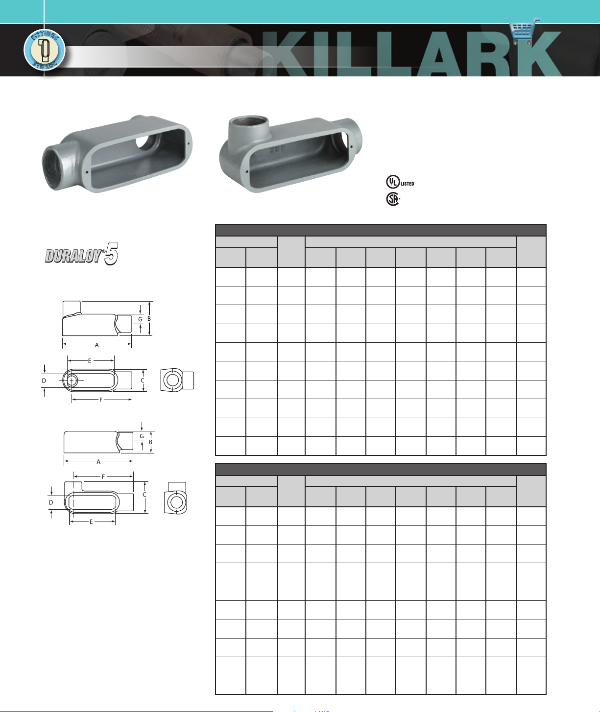
O SERIES / DURALOY® 5 SERIES
C
C
O
O
L
L
ALUMINUM OR MALLEABLE IRON CONDUIT BODIES
• Suitable for wet locations when used with gasketed
covers.
• Federal Specification W-C-586D/A-A 50563.
• Suitable for use in hazardous location applications
when installed according to NEC Ar ticles 501.10(b),
Class I, Div. 2, (Suitable for use in Class I Zone 2
applications) 502.10 and 503.10.
File No. E3397
LB Typ e LL Typ e
Certified File No. L R11852
FEATURES-SPECIFICATIONS
See page F15 for Standard Materials & Finish
Dimensions
LB Type
LL Type
LB TYPE CONDUIT BODY*
CATALOG NUMBER
KILLARK
DURALOY
ALUM.
OLB-1 OLB-1M 1/2”
OLB-2 OLB-2M 3/4”
OLB-3 OLB-3M 1”
OLB-4 OLB-4M 1-1/4”
OLB-5 OLB-5M 1-1/2 ”
OLB-6 OLB-6M 2”
OLB-7 O LB -7M 2-1/ 2”
OLB-8 OLB-8M 3”
OLB-9 OLB-9M 3-1/2”
OLB-0 OLB-0M 4”
IRON
HUB
SIZE
A B C D E F G
4-17/32 ”
13-15/16”
13-15/16”
16-7/8”
16-7/8”
2-9/32”
(115)
5-3/4”
(146)
6-5/8”
(168)
7-1/ 2”
(191)
9-1 /8”
(232)4”(102)
10”
(254)
(354)
(354)
(429)
(429)
(83)
2-1/2 ”
(64)
2-29/32”
(74)
3-3/16”
(81)
4-13/16”
(122)
6-1 /8”
(156)
6-1 /2”
(165)
7-9 /16”
(192)
7-13/16”
(198)
DIMENSIONS
1-3/8”
(35)1”(25)
1-5/8”
(41)
1-7/8 ”
1-15 /32 ”
(48)
2-5/8”
(67)2”(51)6”(152)
2-5/8”
(67)2”(51)6”(152)
3-1/8”
(79)
4-3/8”
3-11/16”
(111)
4-3/8”
3-11/16”
(111)
5-1/2”
(140)
5-1/2”
(140)
1-7/3 2”
(31)
(37)
2-9/16”
(65)
(94)
(94)
4-7/ 8”
(124)
4-7/ 8”
(124)
3-5/32”
3-25/32”
4-17/32 ”
(115)
8-1/16”
(205)
10-5/8”
(270)
10-5/8”
(270)
13-1/8”
(333)
13-1/8”
(333)
(80)
(96)
4-3/8”
(111)
4-29/32”
(125)
5-23/ 32”
(145)
6-13/ 32”
(162)
17-3 /4”
(451)
8-5/32”
(207)
11-7/16”
(29 1)
11-7/16”
(29 1)
13-3/4”
(349)
13-3/4”
(349)
LL TYPE CONDUIT BODY*
CATALOG NUMBER
KILLARK
DURALOY
ALUM.
OLL-1 OLL-1M 1/2”
OLL-2 OLL-2M 3/4”
OLL-3 OLL-3M 1”
OLL-4 OL L-4M 1-1/4”
OLL-5 OLL-5M 1-1/ 2”
OLL-6 OLL-6M 2”
OLL-7 OLL-7M 2 -1/ 2”
OLL-8 OLL-8M 3”
OLL-9 OL L-9M 3 -1/2”
OLL-0 OLL-0M 4”
IRON
HUB
SIZE
A B C D E F G
4-5/8”
5-3/8”
6-1 /4 ”
8-1/8”
8-1/8”
10-9/16”
13-11/16”
13-11/16”
16-1/ 2”
16-1/ 2”
1-3/8”
(117)
(137)
(159)2”(51)
(206)
(206)
(268)
(348)4”(102)
(348)
(419)
(419)
(35)2”(51)1”(25)
1-5/8”
(41)
2-5/8”
(67)
2-3/4”
(70)
3-1/2”
(89)
4-3/4”
(121)
5-1/2”
(140)
5-5/8”
(143)
* For conduit body packaged with cover and gasket, add CG to the catalog number.
DIMENSIONS
3-5/32”
2-3/16”
2-9/16”
4-3/16”
1-7/3 2”
(56)
(65)
3-1/2”
(89)2”(51)6”(152)
3-1/2”
(89)2”(51)6”(152)
(106)
5-3/4”
(146)
5-3/4”
(146)
7-1/ 8”
(181)
7-1/ 8”
(181)
(31)
1-15 /32 ”
(37)
2-9/16”
(65)
3-11/16”
(94)
3-11/16”
(94)
4-7/ 8”
(124)
4-7/ 8”
(124)
3-25/32”
4-17/32 ”
8-1/16”
10-5/8”
10-5/8”
13-1/8”
13-1/8”
(80)
(96)
(115)
(205)
(270)
(270)
(333)
(333)
—
—
—
—
—
—
—
—
—
—
5/8”
(16)
3/4”
(19)
15/16”
(24)
1-3/16”
(30)
1-3/8”
(32)
1-5/8”
(38)
2-1/2 ”
(64)
2-3/16”
(54)
2-1/2 ”
(67)
2-3/4”
(70)
5/8”
(16)
3/4”
(19)
15/16”
(24)
1-3/16”
(30)
1-3/8”
(32)
1-5/8”
(38)
1-13 /16”
(46)
2-3/16”
(54)
2-1/2 ”
(67)
2-3/4”
(70)
VOLUME
CU. IN.
4.0
7.0
12.0
28.8
36.0
70.0
142.0
173. 0
292.0
324.0
VOLUME
CU. IN.
4.0
7.0
12.0
32.0
36.0
70.0
142.0
173. 0
292.0
324.0
Page 3

KILLARK FITTINGS
D
O SERIES / DURALOY® 5 SERIES
ALUMINUM OR MALLEABLE IRON CONDUIT BODIES
• Suitable for wet locations when used with gasketed
covers.
• Federal Specification W-C-586D/A-A 50563.
• Suitable for use in hazardous location applications
when installed according to NEC Ar ticles 501.10(b),
Class I, Div. 2, (Suitable for use in Class I Zone 2
applications) 502.10 and 503.10.
File No. E3397
Certified File No. L R11852
T Ty peLR Typ e
N
I
N
I
T
T
G
G
T
T
I
S
I
S
F
F
S
S
C
C
T
T
O
D
O
L
L
FEATURES-SPECIFICATIONS
See page F15 for Standard Materials & Finish
Dimensions
LR Type
CATALOG NUMBER
KILLARK
ALUM.
DURALOY
IRON
HUB
SIZE
OLR-1 OLR-1M 1/2”
OLR-2 OLR-2M 3/4”
OLR-3 OLR-3M 1”
OLR-4 OLR-4M 1-1/4”
OLR-5 OLR-5M 1-1/2”
OLR-6 OLR-6M 2”
OLR-7 OL R-7M 2 -1/ 2”
OLR-8 OLR-8M 3”
OLR-9 OLR-9M 3-1/2 ”
OLR-0 OLR-0M 4”
LR TYPE CONDUIT BODY*
DIMENSIONS
A B C D E F G
4-5/8”
5-3/8”
6-1 /4 ”
8-1/8”
8-1/8”
10-9/16”
13-11/16”
13-11/16”
16-1/ 2”
16-1/ 2”
1-3/8”
(117)
(35)2”(35)1”(25)
1-5/8”
(137)
(41)
(159)2”(51)
2-5/8”
(206)
(67)
2-3/4”
(206)
(70)
3-1/2”
(268)
(89)
(348)4”(102)
4-3/4”
(348)
(121)
5-1/2”
(419)
(140)
5-5/8”
(419)
(143)
3-5/32”
2-3/16”
2-9/16”
(67)
(65)
1-7/3 2”
(31)
1-15 /32 ”
(37)
3-25/32”
4-17/32 ”
3-1/2”
(89)2”(51)6”(152)
3-1/2”
(89)2”(51)6”(152)
4-3/16”
(106)
5-3/4”
(146)
5-3/4”
(146)
7-1/ 8”
(181)
7-1/ 8”
(181)
2-9/16”
(65)
3-11/16”
(93)
3-11/16”
(93)
4-7/ 8”
(124)
4-7/ 8”
(124)
8-1/16”
10-5/8”
10-5/8”
13-1/8”
13-1/8”
(80)
(96)
(115)
(205)
(270)
(270)
(333)
(333)
4-3/8”
(111)
4-29/32”
(125)
5-23/ 32”
(145)
6-13/ 32”
(162)
17-3 /4”
(451)
9-5/32”
(233)
11-7/16”
(29 1)
11-7/16”
(29 1)
13-3/4”
(349)
13-3/4”
(349)
5/8”
(16)
3/4”
(19)
15/16”
(24)
1-3/16”
(30)
1-3/8”
(32)
1-5/8”
(38)
1-13 /16”
(54)
2-3/16”
(54)
2-1/2 ”
(67)
2-3/4”
(67)
VOLUME
CU. IN.
4.0
7.0
12.0
32.0
31.0
70.0
142.0
173. 0
292.0
324.0
T TYPE CONDUIT BODY*
CATALOG NUMBER
KILLARK
T Type
* For conduit body packaged with cover and gasket, add CG to the catalog number.
DURALOY
ALUM.
OT-1 OT-1M 1/2”
OT-2 OT-2M 3/4”
OT-3 OT-3M 1”
OT-4 OT-4M 1-1/4”
OT-5 OT-5M 1-1/2”
OT-6 OT-6M 2”
OT-7 OT-7 M 2-1/2”
OT-8 OT-8M 3”
OT-9 OT-9M 3 -1/ 2”
OT-0 OT-0M 4”
IRON
HUB
SIZE
A B C D E F G
5-3/8”
6-1 /16”
7-1/ 8”
9-3/16 ”
9-3/16 ”
11-5/8”
15-1/8”
15-1/8”
18-1/8”
18-1/8”
1-3/8”
(137)
(35)2”(35)1”(25)
1-5/8”
(154)
(41)
(181)2”(51)
2-5/8”
(233)
(67)
2-3/4”
(233)
(70)
3-1/2”
(295)
(89)
(384)4”(102)
4-3/4”
(384)
(121)
5-1/2”
(460)
(140)
5-5/8”
(460)
(143)
DIMENSIONS
3-5/32”
2-3/16”
2-9/16”
4-3/16”
1-7/3 2”
(67)
(65)
(31)
1-15 /32 ”
(37)
3-25/32”
4-17/32 ”
3-1/2”
(89)2”(51)6”(152)
3-1/2”
(89)2”(51)6”(152)
(106)
5-3/4”
(146)
5-3/4”
(146)
7-1/ 8”
(181)
7-1/ 8”
(181)
2-9/16”
3-11/16”
3-11/16”
(65)
(94)
(94)
4-7/ 8”
(124)
4-7/ 8”
(124)
8-1/16”
10-5/8”
10-5/8”
13-1/8”
13-1/8”
(80)
(96)
(115)
(205)
(270)
(270)
(333)
(333)
VOLUME
CU. IN.
5/8”
—
(16)
3/4”
—
(19)
15/16”
—
(24)
1-3/16”
—
(30)
1-3/8”
—
(32)
1-5/8”
—
(38)
1-13 /16”
—
(54)
2-3/16”
—
(54)
2-1/2 ”
—
(67)
2-3/4”
—
(67)
4.0
7.0
12.0
32.0
33.0
70.0
142.0
173. 0
292.0
324.0
Page 4

KILLARK FITTINGS
D
N
I
N
I
T
T
G
G
T
T
I
S
I
S
F
F
S
S
T
T
D
O SERIES / DURALOY® 5 SERIES
C
C
O
O
L
L
ALUMINUM OR MALLEABLE IRON CONDUIT BODIES
TA Ty pe
TB Typ e X Ty pe
FEATURES-SPECIFICATIONS
See page F15 for Standard Materials & Finish
Dimensions
TA Type
CATALOG NUMBER
KILLARK
DURALOY
ALUM.
OTA-1 OTA-1M 1/2”
OTA-2 OTA-2M 3/4”
IRON
— OTA-3M 1”
CATALOG NUMBER
KILLARK
DURALOY
ALUM.
OTB-1 OTB-1M 1/2”
OTB-2 OTB-2M 3/4”
OTB-3 OTB-3M 1”
OTB-4 OTB-4M 1-1/4”
OTB-5 OTB-5M 1-1/2”
OTB-6 OTB-6M 2”
IRON
HUB
SIZE
HUB
SIZE
• Suitable for wet locations when used with gasketed
covers.
• Federal Specification W-C-586D/A-A 50563.
• Suitable for use in hazardous location applications
when installed according to NEC Ar ticles 501.10(b),
Class I, Div. 2, (Suitable for use in Class I Zone 2
applications) 502.10 and 503.10.
File No. E3397
Certified File No. L R11852
TA TYPE CONDUIT BODY*
DIMENSIONS
A B C D E F G
5-3/8”
6-1 /16”
7-1/ 8”
(137)
(154)
(181)
2-1/8 ”
(54)2”(51)1”(25)
2-15/16”
2-11/16”
(75)
(68)
2-3/16”
(56)
2-9/16”
(65)
1-7/3 2”
(29)
1-15 /32 ”
(35)
3-5/32”
(80)
3-25/32”
(96)
4-17/32 ”
(115)
—
—
—
TB TYPE CONDUIT BODY*
DIMENSIONS
A B C D E F G
5-3/8”
6-1 /16”
7-1/ 8”
9-3/16 ”
9-3/16 ”
11-5/8”
(137)
(160)
(181)
(233)
(233)
(295)
2-1/8 ”
(54)
2-5/16”
(59)
2-11/16”
(68)
3-9/16”
(90)
3-3/4”
(92)
4-5/8”
(117)
1-5/16”
(33)1”(25)
1-9/16”
1-13 /16”
1-7/3 2”
(40)
(46)
2-1/2 ”
(64)2”(51)6”(152)
2-1/2 ”
(64)2”(51)6”(152)
3-1/8”
(79)
3-25/32”
(31)
1-15 /32 ”
(37)
2-9/16”
(65)
3-5/32”
(80)
(96)
4-17/32 ”
(115)
8-1/16”
(205)
—
—
—
—
—
—
5/8”
(16)
3/4”
(19)
15/16”
(24)
5/8”
(16)
3/4”
(19)
15/16”
(24)
1-3/16”
(30)
1-3/8”
(35)
1-5/8”
(41)
VOLUME
CU. IN.
4.0
7.0
12.0
VOLUME
CU. IN.
4.0
7.0
12.0
32.0
36.0
70.0
TB Type
X Type
CATALOG NUMBER
KILLARK
DURALOY
ALUM.
OX-1 OX-1M 1/2”
OX-2 OX-2M 3/4”
OX-3 OX-3M 1”
OX-4 OX-4M 1-1/ 4”
OX-5 OX-5M 1-1/ 2”
OX-6 OX-6M 2”
IRON
HUB
SIZE
X TYPE CONDUIT BODY*
DIMENSIONS
A B C D E F G
5-3/8”
6-1 /16”
7-1/ 8”
9-3/16 ”
9-3/16 ”
11-5/8”
1-3/4”
(137)
(160)2”(51)
(181)
(233)
(233)
(295)
(44)
2-1/4”
(57)
2-9/16”
(65)
2-3/4”
(70)
3-3/8”
(85)
1-11/ 16”
(43)1”(25)
2-7/8”
(73)
3-3/8”
1-15 /32 ”
(86)
4-1/2”
(114)2”(51)6”(152)
4-1/2”
(114)2”(51)6”(152)
5-1/4”
(133)
1-7/3 2”
(31)
(37)
2-9/16”
(65)
3-5/32”
3-25/32”
4-17/32 ”
8-1/16”
(80)
(96)
(115)
(205)
—
—
—
—
—
—
5/8”
(16)
3/4”
(19)
15/16”
(24)
1-3/16”
(30)
1-3/8”
(35)
1-5/8”
(41)
VOLUME
CU. IN.
4.0
7.0
12.0
32.0
36.0
70.0
* For conduit body packaged with cover and gasket, add CG to the catalog number.
Page 5

D
COVERS AND GASKETS
Neoprene GasketAluminum and Steel Stamped Covers
Cast Iron Covers Fiber Gasket
KILLARK FITTINGS
O SERIES / DURALOY® 5 SERIES
• Suitable for wet locations when used with gasketed
covers.
• Federal Specification W-C-586D/A-A 50563.
• Suitable for use in hazardous location applications
when installed according to NEC Ar ticles 501.10(b),
Class I, Div. 2, (Suitable for use in Class I Zone 2
applications) 502.10 and 503.10.
File No. E3397
Certified File No. L R11852
N
I
N
I
T
T
G
G
T
T
I
S
I
S
F
F
S
S
C
C
T
T
O
D
O
L
L
FEATURES-SPECIFICATIONS
Stamped Material/Finish
Copper-free Aluminum
(less than 4/10 of 1%)
• Natural finish
• 300 Series stainless steel screws
Galvanized Steel
• Natural finish
• 300 Series stainless steel screws
Cast Material/Finish
Duraloy Malleable Iron
• Tri-coat finish of electrozinc, chromate
sealant, and electrostatically applied
powder coating
• 300 Series stainless steel screws
ALUMINUM AND STEEL STAMPED COVERS
CATALOG NUMBER
KILLARK
ALUMINUM
OL-10 OL-10 M 1/2” 3-15/16”(100) 1-3/8”(35) 3/8”(10)
OL-20 OL-20M 3/4” 4-5/8”(117) 1-5/8”(41) 3/8”(10)
OL-30 OL-30M 1” 5-3/8”(137 ) 1-7/8 ”(4 8) 5/8”(16)
OL-4 50 OL-45M 1-1 /4 ” 7-3/ 16”(18 3) 2-5/8”(67) 5/8”(16)
OL-4 50 OL-45M 1-1/2 ” 7-3 /16”(183) 2-5/8”(67) 5 /8”(16)
OL-60 OL-60M 2” 9-1/ 2”(241) 3-1/8”(79) 5/8”(16)
OL-780 OL-78M 2-1 /2” 12-1/4”(311) 4- 3/8 ”(111) 5/8”(16)
OL-780 OL-78M 3” 12-1/4”(311) 4- 3/8 ”(111) 5/8”(16)
OL-900 OL-90M 3-1/ 2” 14-7/ 8”(378) 5-1/ 2”(14 0) 5/8”(16)
OL-900 OL-90M 4” 14-7/8 ”(3 78) 5-1/2”(14 0) 5/8”(16)
STEEL LENGTH WIDTH HEIGHT
HUB
SIZE
DIMENSIONS
CAST IRON COVERS
CATALOG
NUMBER
OL-10 CM 1/2” 3-15/16”(100) 1-3/8”(3 5) 3/8”(10)
OL-20 CM 3/4” 4-5/8”(117) 1-5/8”(41) 3/ 8”(10)
OL-30CM 1” 5-3/8”(13 7) 1-7/8”(4 8) 5/8”(16)
OL-4 5CM 1-1/4 ” 7-3/ 16”(18 3) 2-5/8”(67) 5/8”(16)
OL-4 5CM 1-1/2” 7-3/ 16”(18 3) 2-5/8”(67) 5/8”(16)
OL-60CM 2” 9-1/2 ”(241) 3-1/8”(79) 5/8”(16)
OL-78CM 2 -1/ 2” 12-1/4”(311) 4- 3/8 ”(111) 5/8”(16)
OL-78CM 3” 12-1/4”(311) 4-3 /8”(111) 5/8”(16)
OL-90CM 3-1/ 2” 14-7/8 ”(378) 5-1/ 2”(140 ) 5 /8”(16)
OL-90CM 4” 14-7/ 8”(378) 5-1/2”(14 0) 5/8”(16)
HUB
SIZE
LENGTH WIDTH HEIGHT
DIMENSIONS
Material/Finish
• Neoprene or fiber
HUB
SIZE
1/2” OLK-1RG OLK-1VG
3/4” OLK-2RG OLK-2VG
1” OLK-3RG OLK-3VG
1-1/4” OL-45-RG OL-45-VG
1-1/ 2” OL-4 5-RG OL-45-VG
2” OL-6-RG OL-6-VG
2-1/2 ” OL-78-RG OL-78-VG
3” OL-78-RG OL-78-VG
3-1/2” OL-90-RG OL-90-VG
4” OL-90-RG OL-90-VG
GASKETS
CATALOG NUMBER
NEOPRENE FIBER
 Loading...