

Page 1
JUNCTION BOXES
KILLARK ENCLOSURES
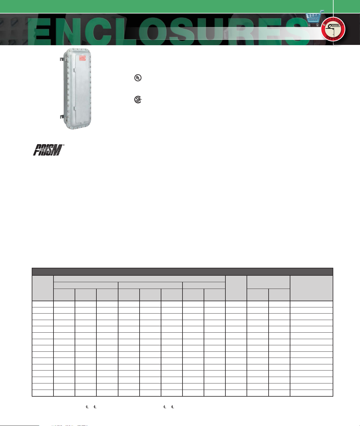
B7E SERIES
S
S
U
O
U
O
L
L
R
R
C
C
E
E
N
S
N
S
E
E
H
H
C
C
A
A
O
O
Z
Z
L
L
FEATURES-SPECIFICATIONS
Applications
• Locations made hazardous due to the
presence of flammable gases or vapors,
combustible dust, or easily ignitable fibers
and flyings, and areas which are subject to
corrosion, weather and dampness
• Petroleum Refineries, Chemical and
Petrochemical plants with indoor and
outdoor process
• Applications requiring junction, pull and/
or splice boxes
• Enclosures to house control stations,
relays, starters, circuit breakers, terminal
blocks and other equipment or devices
(Glass viewing windows cannot be added to the Prism
Series Enclosures. Use Killark Quantum Enclosures
when viewing windows are required.)
#UL1203 - E xplosion proof and dustignition-proof electrical equipment for use
in hazardous (classified) locations. File
#E83969
#C22.2 No. 3 0-M1986-Explosion -proof
Enclosure for use in Class I Hazardous
Locations. FILE #LR11716
Features
• Copper-free cast aluminum construction.
High strength, lighter in weight, corrosion
resistant
• Quick Release, Captivated Cover Bolts
of 316 Grade Stainless Steel. Triplelead bolts require only 3-1/2 turns to
disengage. Stainless steel (316 grade) for
maximum protection from corrosion
• Gasketed Flange. Nitrile (BUNA-N) “O”
ring gasket is located inside bolt circle to
prevent water seeping into enclosure
• Ductile Mounting Lugs. Lugs are made
of ductile aluminum alloy to adjust to
irregular mounting surfaces without
damage to enclosure
• Hinged Cover is Standard
Class I, Div. 1 & 2,
Groups B, C, Dj
Class I, Zone 1 & 2
Groups IIB + H2, IIA
Class II, Div. 1 & 2,
Groups E, F, G
Class III, Div. 1 & 2
Enclosure Type 3, 4, 4X
NEMA 3, 4, 4x, 7 (B, C, D), 9 (E, F, G)
• Recessed Flange Notches. Flanges are
notched to allow for easier cover opening
with prying instrument without flange
damage
• Conduit Openings. Conduit openings can
be supplied at factory, or can be field
installed.
Material/Finish
• Enclosure: Cast Copper-free Aluminum
(less than 4/10 of 1%)
• Hinges: Aluminum with stainless steel
hardware
• Cover Bolts: 316 Grade Stainless Steel
• Aluminum Lacquer Paint Finish Standard
on all B7E except B7EP and B7EQ which
are powder epoxy as standard
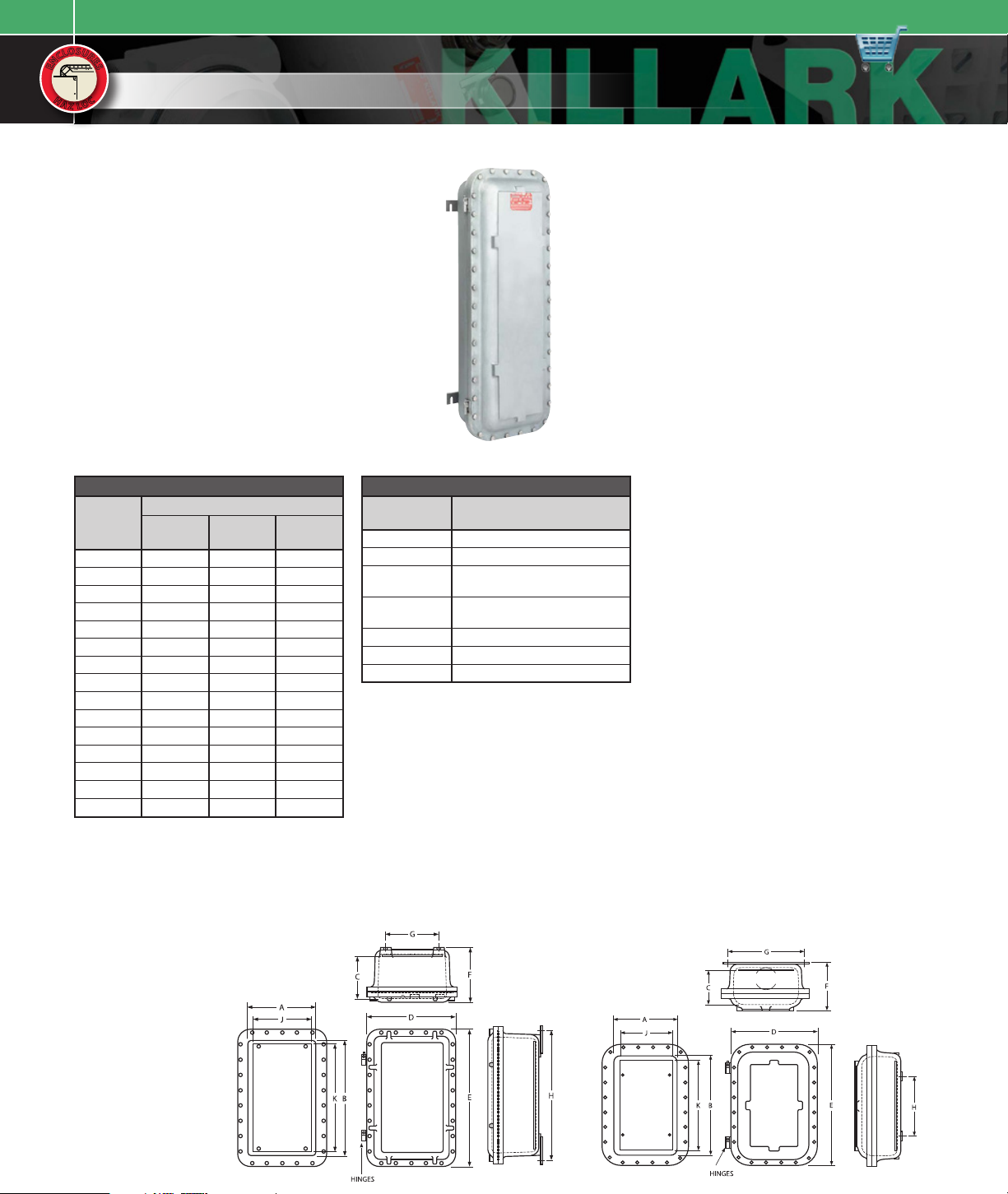
B7E JUNCTION BOXES AND ENCLOSURES
DIMENSIONS
CATALOG
NUMBER
B7EA 6-1 /2” 13-1/2” 6-11 /16” 11” 18” 9-1 /8” 3-5/8” 16-3/8” 1 1-1/ 2” 1” 4 rows of 2 = 8
B7EB 10” 18-1/2 ” 6-5/8” 14-1 /2” 23” 9-1 /8” 7” 2 1-3/8” 1 1-1/ 2” 1” 7 rows of 3 = 21
B7EC 8” 15-1/2 ” 6-11 /16” 12-1 /2” 20” 9-1 /8” 5” 18-3/8” 1 1-1/2” 1” 5 rows of 2 = 10
B7ED 10” 21” 6-11/ 16” 14-1/ 2” 25-1/2” 9-1 /8” 7” 23 -7/8 ” 1 1-1/2” 1” 8 rows of 3 = 24
B7EE 8” 21-3/4” 8-5/16” 12 -1/ 2” 26 -1/4” 10-3 /4” 5” 24-5/8” 1 2” 2” 8 rows of 2 = 16
B7EF 13” 22-3/4” 8-3/8” 17-7/ 8” 27-1 /4” 11” 10-3 /8” 25-5/8” 1 4” 4” 8 rows of 4 = 32
B7EG 12” 29-3/4” 8-7/ 8” 16 -1/ 2” 34-1/4 ” 11-1/ 2” 9” 32-5/8” 1 5” 4” 8 rows of 3 = 24
B7EH 17” 29-3/4” 8-11/16 ” 21-1/2” 34-1 /4” 11-7/8” 14” 32-5/8” 1
B7EJ 15-1/ 2” 57-1/ 2” 9-5/16” 20-1/4 ” 62-1/4” 15” 18-1/2” 43 -1/2” 2 5” 5” 18 rows of 4 = 72
B7EK 13” 20” 6-5/8” 17-1/2 ” 24-3/4” 9-1/2” 15 -1/ 4” 13” 2 3” 1-1/2 ” 6 rows of 4 = 24
B7EL 13” 29” 6-5/8” 17-1/2” 33-3/8” 9 -1/2” 15-1/4” 21” 2 3” 1-1 /2” 9 rows of 4 = 36
B7EM 13” 41” 6-5/8” 17-1/2” 45-3/8” 9 -1/2” 15-1/4” 33” 2 3” 1-1/2” 14 rows of 4 = 56
B7EN 13” 50” 6-5/8” 17-1/ 2” 54-3/8” 9-1/2” 15 -1/4” 42” 2 3” 1-1/ 2” 17 rows of 4 = 68
B7EPl
B7EQl
jAll Conduits must be sealed within 18” when used in G roup B Locations.
kOperator spacing is 2-1/2” to except on B7EG & B7EH spacing is 3” to . Internal Mounting Pan Thickness is 1/8”
except on B7EJ it is 3/16” thick. B7EJ Enclosure Cover has an Internal Rib Structure. Consult Killark for drawing details
before layout of cover devices. Maximum number of “G” series control operators permitted in cover, down + across = total.
lB7 COMPACT Series - Details on page E39.
NOMINAL INSIDE OUTSIDE MOUNTING
WIDTH
3-5/8” 5-13/ 16 ” 5 -1/16 ” 5-3/4” 8 -1/ 16” 6-5/16” 3-1/8” 8 -1/ 8” 1 1” 1” 1 row of 2 = 2
4-1/4” 9-3/ 16” 6-5/16” 8 -1/8” 13-1/16” 7-13/16” 6-3/8” 7-1/2 ” 2 1-1/ 2” 1-1/2 ” 1 row of 4 = 4
(A)
LENGTH
(B)
DEPTH
(C)
WIDTH
(D)
LENGTH
(E)
DEPTH
(F)
WIDTH
(G)
LENGTH
DRAWING
FIGURE
(H)
MAXIMUM CONDUIT
SIZE
TOP &
BOTTOM
5” 4” 9 rows of 5 = 45
SIDES
MAXIMUM NUMBER
OF OPERATORSk
Page 2
KILLARK ENCLOSURES
S
S
U
O
U
O
L
L
R
R
C
C
E
E
N
S
N
S
E
E
H
H
A
A
Z
Z
B7E SERIES
C
C
O
O
L
L
FEATURES-SPECIFICATIONS
JUNCTION BOXES
B7E JUNCTION BOXES AND ENCLOSURES
CATALOG
NUMBER
CATALOG
NUMBER
B7EA 19919 5” 11-3/4”
B7EB 199 20 8-1 /4” 16-3/4”
B7EC 18245 6-1/4 ” 13-3 /4”
B7ED 19921 8-3/8” 19-3/8”
B7EE 19923 6-3/8” 20-3/8”
B7EF 18 472 11-5/8” 21-1/4”
B7EG 19924 10” 28”
B7EH 19925 15-3/ 8” 28-3/8”
B7EJ 18279 13-1/2 ” 54”
B7EK 199 26 11” 18”
B7EL 19927 11” 27”
B7EM 199 28 11” 39”
B7EN 19929 11” 47”
B7EPk
B7EQk
— N/A N/A
— N/A N/A
jInternal Mounting Pan Thickness is 1/8” except on
B7EJ it is 3/16” thick.
kB7 COMPACT Series - Details on page E39.
Dimensions
PANj
WIDTH (J)
Figure 1 Figure 2
LENGTH
(K)
(See page E37)
MODIFICATIONS
SUFFIX
NUMBER
KIT-251 100 amp ground lug
KIT-252 225 amp ground lug
SU3B4X
SU94
SU9 Special paint finish
SU14 Fungus proofing of enclosure
SU93 Do not paint enclosure
DESCRIPTION
Drain & breather installed
(GRPs B, C & D T YPE 4X )
“Drill, tap & plug for future”
drain & breather
 Loading...