

KILLARK MCX Series Installation, Operation & Maintenance Manual
HUBBELL ELECTRICAL PRODUCTS
A Division of HUBBELL INCORPORATED
CAUTION:
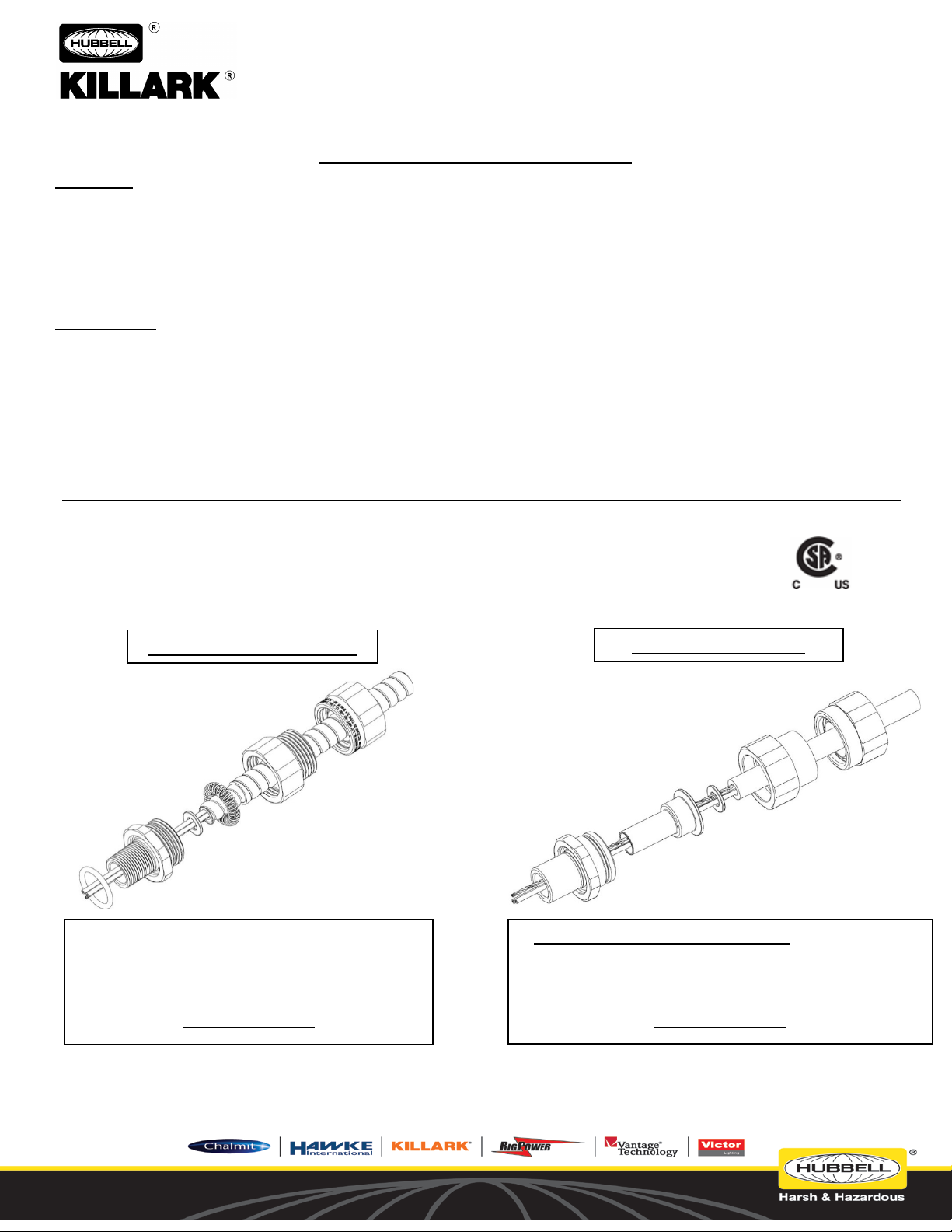
Armored Cable Assembly
Tray Cable Assembly
REMOVE GROUNDING SPRING TO USE WITH
USE FOR TYPE MC, MC-HL, TECK90,
(Delaware)
3940 Martin Luther Kind Drive
St. Louis, Missouri 63113 USA
For use in Zone Classified Hazardous Locations
INSTALLA T ION, OPERATION &
MAINTENANCE D ATA SH E ET
MCX CABLE GLANDS
MCX SERIES CABLE GLANDS
Before installing, make sure you are compliant with area classifications, as failure to do so may result in bodily injury, death and property damage. Do not
attempt installation until you are familiar with the following procedures. All installati on must comply with the applic abl e Electrical Code(s).
Make sure that the circuit is de-energized before starting installation or maintenance.
Verify that the installation is grounded. Failure to ground will create electrical shock hazards, which can cause serious injury and or death.
IMPORTANT:
Please read these instructions carefully before installing or maintaining this equipment. Good electrical practices should be followed at all times and this
data should be used as a guide only.
Technical information, advice and recommendations contained in these documents is based upon information that Killark believes to be reliable. All the
information and advice contained in these documents is intended for use only by persons having been trained and possessing the requisite skill and knowhow and to be used by such persons only at their own discretion and risk. The nature of these instructions is informative only and does not cover all of the
details, variations or combinations in which this equipment may be used, its storage, delivery, installation, check out, safe operation and maintenance.
Since conditions of use of the product are outside of the care, custody and control of Killark, the purchaser should determine the suitability of the product
for his intended use, and assumes all risk and liability whatsoever in connection therewith.
Class I, Division 1, Group s A, B, C, D
Class II, Division 1, Gro u ps E, F, &G; Class III.
Type 3, 4, and 4X, IP66, Operating Temperature Range -50°C +60°C
TECK90-HL, RA90, RA90-HL, AC90, AC90-
HL, ACWU90, & ACWU90-HL CABLE.
SEE PAGES: 2-3
P/N KIL 00921499 FORM NO, K1499 MCX Series Cable Glands Page 1 of 7
TYPE TC-ER-HL, TC, TC-ER, PLTC, PLTC-ER,
ITC, ITC-ER, MV & MARINE SHIPBOARD CABLE.
SEE PAGES: 4-7
HUBBELL ELECTRICAL PRODUCTS
A Division of HUBBELL INCORPORATED
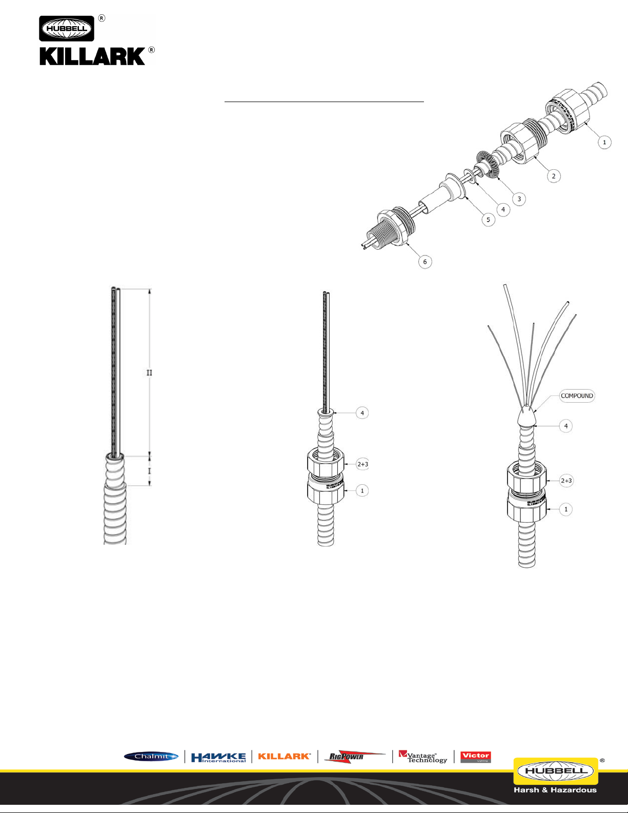
Back Nut
Armored Cable Assembly
Cable Preparation
Cable Gland Preparation
Potted Wire Preparation
(Delaware)
3940 Martin Luther Kind Drive
St. Louis, Missouri 63113 USA
For use in Zone Classified Hazardous Locations
INSTALLA T ION, OPERATION &
MAINTENANCE D ATA SH E ET
1.
2.
Middle Nut
3.
Grounding Spring (Captive in the Middle Nut)
4.
Armor Stop
5.
Potting Chamber
6.
Entry Component
MCX CABLE GLANDS
A)
Strip cable to suit equipment as shown
above, exposing metal armor sheath (I)
and insulated cores (II).
I = 3/4" (19mm) for ½” size glands
I = 13/16" (21mm) for ¾” size glands
I = 1" (25mm) for 1” size glands
I = 1-1/4" (32mm) for 1 ¼” size glands
I = 2-3/8” (60 mm) for 1 ½” size glands
I = 2-5/8” (66mm) for 2” size glands
I = 2-13/16” (71 mm) for 2 ½” size glands
I = 3” (76 mm) for 3” size glands
I = 2-3/4” (70 mm) for 3 ½” size glands
I = 3-1/8” (79 mm) for 4” size glands
II to suit equipment
P/N KIL 00921499 FORM NO, K1499 MCX Series Cable Glands Page 2 of 7
B)
Push the cable through the back
nut (1), middle nut (2), and
grounding spring (3). Locate the
armor stop (4) at the end of the
armor as shown above. If the
conductors are too large to f it
through the armor stop (4) it can be
removed from the assembly. The
entry component (6) has a built in
armor stop for larger cables.
C)
Spread out the cable cores
and the individual strands of
un-insulated conductors for
the packing of the compound.
Pack the compound between
the cores and strands as
shown above. See Page 3 for
compound preparation details.
HUBBELL ELECTRICAL PRODUCTS
A Division of HUBBELL INCORPORATED
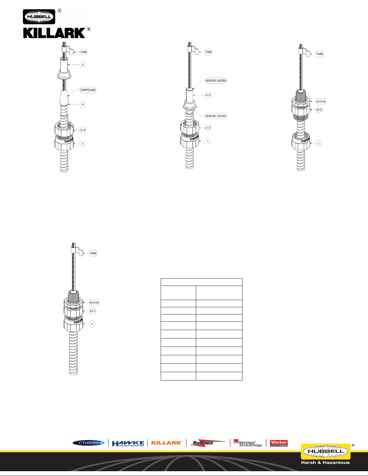
Table A
Assembly
Torque (l bf-ft)
½”
20
¾”
20
1”
30
1 ¼”
40
1 ½”
136
2”
136
2 ½”
158
3”
181
3 ½”
181
4”
181
the circuit.
(Delaware)
3940 Martin Luther Kind Drive
St. Louis, Missouri 63113 USA
INSTALLA T ION, OPERATION &
MAINTENANCE D ATA SH E ET
For use in Zone Classified Hazardous Locations
MCX CABLE GLANDS
D)
With all gaps and voids filled, bring the
conductors back together and pack more
compound around the outside of the
conductors. Tape the conductors together to
prevent disturbance of the compound. Press
the potting chamber (5) over compound until
it hits the armor stop (4) or the end of the
armor. Do not twist the potting
chamber (5) while pressing it over the
compound. Twisting may create voids in
the seal.
G)
Thread the back nut (1) onto the middle nut
(2) to the torque show in Table A
(Approximately hand tight +1 turn). This
will compress the seal inside the back nut
(1) to grip the jacket of the cable for
mechanical retention and the formation of
an environmental seal. Allow the
compound to fully cure before energizing
E)
Ensure that the entire potting
chamber
(5) is filled with compound then
remove any excess compound from
the potting chamber (5). Ensure that
all of the compound is removed from
the tapered surface of the potting
chamber (5) that contacts the
grounding spring. (3) Failing to
remove compound from this surface
will interfere with the compression of
the spring and may impede the
grounding path of the gland.
Gland Size
F)
IMPORTANT NOTE:
THE CONDUCTORS MUST
NOT BE MOVED FOR A
MINIMUM OF FOUR HOURS.
TAKE CARE DURING STEPS F
AND G TO ENSURE THAT THE
CONDUCTORS DO NOT MOVE.
If the gland is to be installed in a
threaded opening first thread the
entry component (6) into the
enclosure to prevent twisting of
the cable. When installing the
entry component (6) into a NPT
entry the component should be
installed hand tight and then one
additional turn with a wrench.
If the entry component (6) is
installed with a locknut it should
tighten to the torque shown in
Table A. (Approximately hand
tight +1 turn)
Slide the potting chamber (5) into
the entry component (6). Take
care to prevent compound from
adhering to the inside of the entry
component (5).
Thread the middle nut (2) onto the
entry component (6) to the torque
show in Table A (Approximately
hand tight +1 turn). This will
compress the grounding spring (3)
to grip the armor for grounding.
P/N KIL 00921499 FORM NO, K1499 MCX Series Cable Glands Page 3 of 7
 Loading...