

KILLARK KF1L SERIES Installation Operation & Maintenance
Page 1 of 8
3940 Dr. Martin Luther King Drive
St. Louis, MO 63113
P/N KIL00921415 FORM NO. K1415 7/13 ERO-6-019-13_2
INSTALLATION, OPERATION &
MAINTENANCE DATA SHEET
FOR
KF1L SERIES LED LUMINAIRE FLOOD
CLASS I DIVISION 1, CLASS II DIVISION 1, OR CLASS I
ZONE 1 HAZARDOUS LOCATIONS.
KF1L SERIES LED LUMINAIRE FLOOD
CAUTION:
Before installing, make sure you are compliant with area classications, failure to do so may result in bodily
injury, death and property damage. Do not attempt installation until you are familiar with the following
procedures. All installation must comply with the applicable Electrical Code.
Make sure that the circuit is de-energized before starting installation or maintenance.
Verify that the installation is grounded. Failure to ground will create electrical shock hazards, which can cause
serious injury and or death.
Note: Due to the surge protection provided in the xture to protect the internal electronics and LEDs, a branch
circuit with the LED xture may false fail a megohmmeter test (sometimes referred to as a megger test. If a
megohmmeter test is required, the LED xture should be removed from the branch circuit.
Note: Multiple uorescent or LED xtures attached to a single Ground Fault Circuit Interrupter (GFCI) may
cause nuisance tripping of the GFCI. Regulatory agencies allow a small amount of leakage current because
of the circuitry required to mitigate possible issues with electromagnetic compatibility (reference UL8750 and
EN61347). The summation of these leakage currents from multiple xtures may be enough to trip a GFCI.
IMPORTANT:
Please read these instructions carefully before installing or maintaining this equipment. Good electrical
practices should be followed at all times and this data should be used as a guide only.
Technical information, advice and recommendations contained in these documents is based upon information
that Killark believes to be reliable. All the information and advice contained in these documents is intended
for use only by persons having been trained and possessing the requisite skill and know-how and to be used
by such persons only at their own discretion and risk. The nature of these instructions is informative only and
does not cover all of the details, variations or combinations in which this equipment may be used, its storage,
delivery, installation, check out, safe operation and maintenance. Since conditions of use of the product are
outside of the care, custody and control of Killark, the purchaser should determine the suitability of the product
for his intended use, and assumes all risk and liability whatsoever in connection therewith.
Page 2 of 8
3940 Dr. Martin Luther King Drive
St. Louis, MO 63113
P/N KIL00921415 FORM NO. K1415 7/13 ERO-6-019-13_2
Luminaires are designed to be installed in Class
I Division 1, Class II Division 1, or Class I Zone 1
Hazardous locations.
Verify that luminaire is grounded. Failure to ground
will create electrical shock hazards, which can cause
serious injury and or death.
NOTE - For Class I, Division 1 / Class II, Division
1 / Class I, Zone 1 Hazardous Locations, use rigid
conduit or cable and connectors / glands rated for
Class I, Division 1 Groups BCD (or Zone I IIB + H2)
hazardous areas.
The KF1L is factory-sealed and does not require a
sealed entry.
INSTALLATION INSTRUCTIONS
FLOOD LIGHT WITH YOKE MOUNT
(See Figure 1)
1. For convenience, install the yoke bracket on
the trunnion (swivel point) before mounting the
structure.
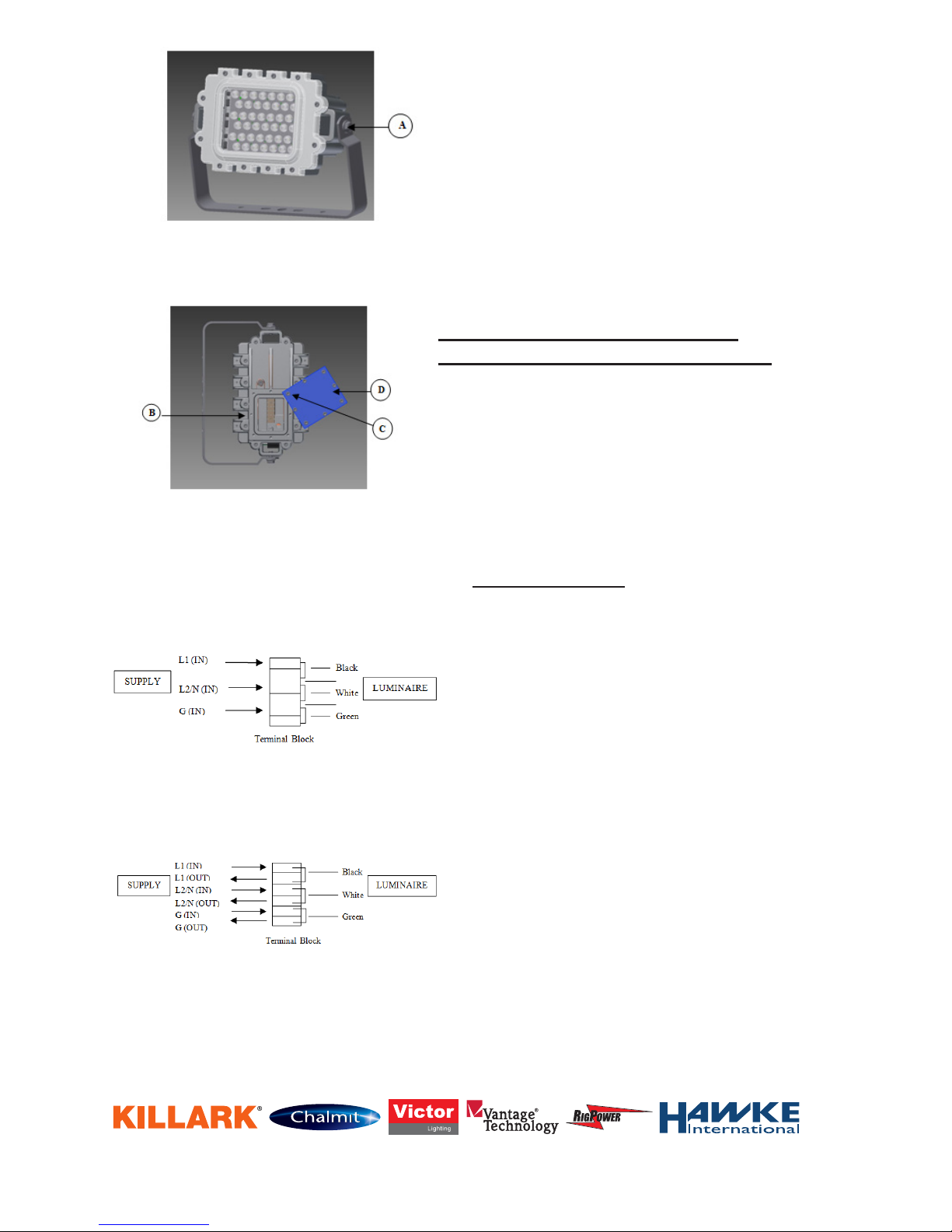
2. Loosen bolts (A) - aim the oodlight to the
desired spot.
3. Tighten both bolts (A) securely.
4. Fasten the yoke bracket to the mounting location
using ½” bolts/fasteners.
IMPORTANT NOTE
Turn off electricity to circuit at main fuse or at
circuit breaker.
5. Run supply wire to xture through applicable hub
(B) on the side of the xture. Make watertight
joint using sealing ttings at threaded hub on
the side of the xture. The hub is threaded
¾”-14NPT (North American version) or M20
(International version).
6. Loosen and remove all but one of the access
door captive screws (C). Rotate access door (D)
to allow for access into terminal chamber. See
Figure 2 for more details.
7. CAUTION - Connection as described below
requires the use of a factory installed terminal
block assembly. See diagrams on left.
8. Replace access door (D) and access door
captive screws (C). Securely tighten screws (C).
See Figure 2 for more details.
9. Turn ON electricity to verify xture is operating
properly.
Figure 1
KF1L Series Typical Assembly
Figure 2
KF1L Series Factory Installed Terminal Block
Connection Method
(Insulated Terminal Block Assembly)
Loop In / Loop Out Wiring Method
Connection Method
(Insulated Terminal Block Assembly)
Standard Wiring Method
Page 3 of 8
3940 Dr. Martin Luther King Drive
St. Louis, MO 63113
P/N KIL00921415 FORM NO. K1415 7/13 ERO-6-019-13_2
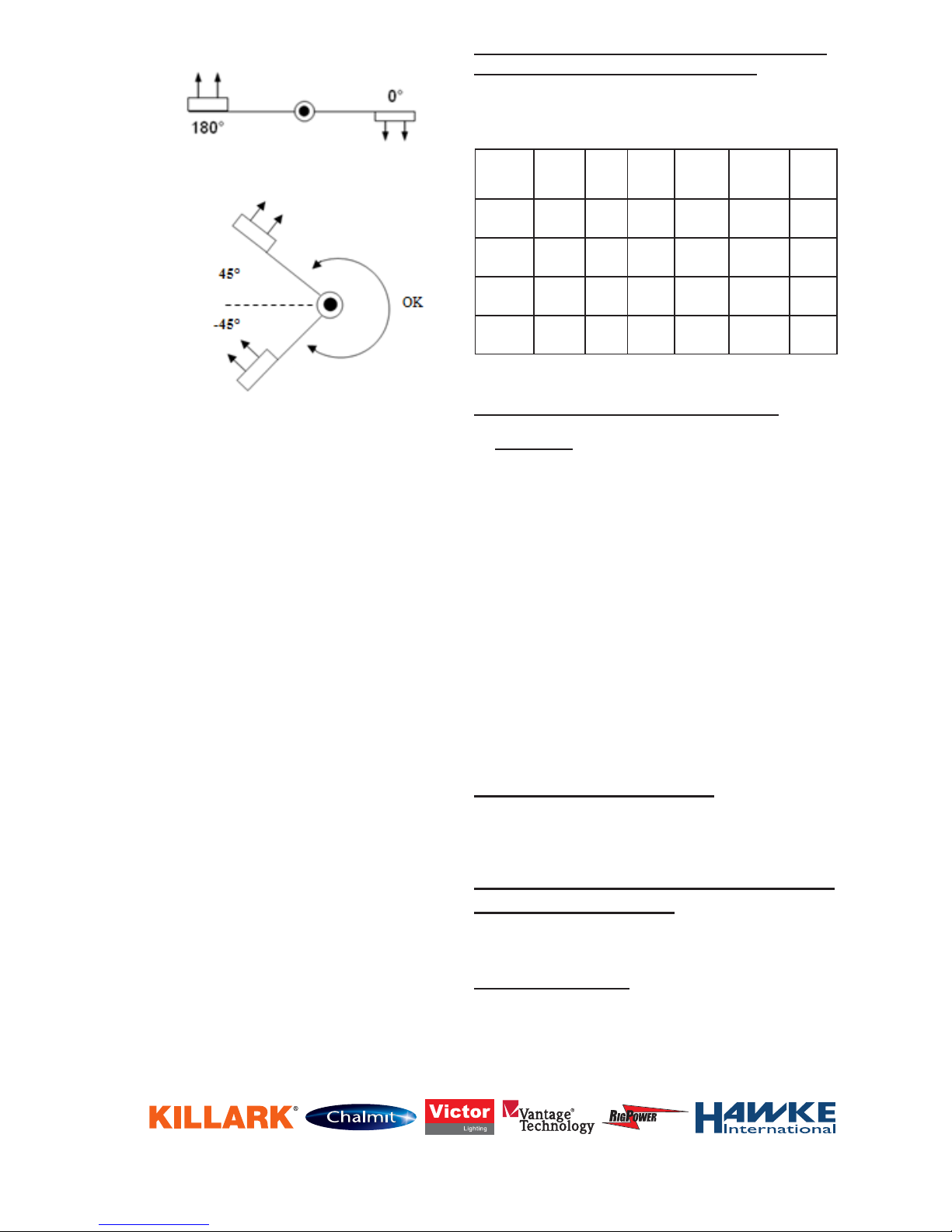
Aiming Designations (Applies to Class and
Division Designated Fixtures Only)
The gures on left refer to nameplate data as
applicable. NOTE: For aiming designation “B”, verify
that the luminaire is not pointed straight up (180°).
Luminaire
Wattage
Ambient
C1 D1
T-Code
C1 D1
Aiming
Range
Diagram
C2 D1
T-Code
Groups
C2 D1
Aiming
Range
Diagram
125 40
55
T6
T5
AAT3C/T3C
T3A/T3C
EFG / EFG
EF / EFG
A / B
A / B
110 40
55
T6
T6
AAT3C / T3C
T3A / T3C
EFG / EFG
EF / EFG
A / B
A / B
105 40
55
T6
T6
AAT3C / T3C
T3A / T3C
EFG / EFG
EF / EFG
A / B
A / B
90 40
55
T6
T6
AAT3C / T3C
T3A / T3C
EFG / EFG
EF / EFG
A / B
A / B
Fig.A
Fig.B
MAINTENANCE INSTRUCTIONS
CAUTION
Disconnect the supplying circuit before opening
xture or removing optics. To maintain maximum
light output, this xture should be cleaned
periodically. Maintenance procedures sometimes
require xtures to be hosed down for good
housekeeping. The supply circuit must be turned
OFF and the xture lens must be allowed to cool
to the ambient room temperature before cleaning.
Only mild, non-abrasive cleaning agents should be
used. The force of water applied by a hose must
not exceed 65 gallons per minute coming from a
1” diameter hose applied at a distance of 10 feet.
These periodic cleaning procedures are important
to prevent the accumulation of dust and dirt which
will impair the light output of the xture. The glass
lens should be regularly inspected for scratches
and chips and, if damaged, must be replaced.
HIGH VIBRATION AREAS
Periodic inspection of lens tightness is required;
recommended every six (6) months.
DIRECTIONS FOR INSTALLATION OF
KF1L ACCESSORIES
NOTE – Reector (KF1L-DARK) and Guard (KF1LG)
cannot be used simultaneously.
KF1L-DARK Reector
IMPORTANT- Before installing, check the xture
nameplate to be sure you have the correct xture.
WARNING- Turn OFF the supplying circuit before
starting installation.
 Loading...