


數位扭力計操作手冊
DIGITAL TORQUE METER INSTRUCTION MANUAL
KTM - 10
KTM - 100
KTM - 50S
KILEWS JAPAN CO., LTD.
http://www.kilews.com Y2F064-003

操作前請閱讀全部說明
一. 安全警告 !!
1. 工作場所要保持乾淨。
◎ 雜亂的工作區域及臺面容易造成傷害。
2. 注意工作場所的環境。
◎ 勿將扭力計置放於雨中或潮濕處。
◎ 請在正常室溫下(約 24℃)使用扭力計。
◎ 工作場所應照明良好。
◎ 勿于有易燃液體或氣體之處所使用扭力計。
3. 勿讓孩童接近。
◎ 除操作人員以外應避免他人靠近工作場所。
4. 穿著適宜。
◎ 勿穿著太寬鬆的衣物或珠寶,以免操作工具時勾扯拉到。
Digital Torque Meter
5. 謹慎操作。
◎ 操作扭力計時應小心使用,注意操作方式及工作場所安全。
6. 穩固的固定機身主體。
◎ 當測量較大扭力時應使用夾子或虎頭鉗等工具來固定起子,如此會比較安全,同時可用雙手操作起子。
7. 勿測試超過負荷量的扭力。
◎ 若測試超過負荷量會使儀器損壞甚至產生意外或傷害。
8. 勿拆卸、撞擊或震動儀器。
◎ 自行拆卸儀器或儀器遭過度撞擊、震動,可能導致儀器損壞。
9. 電擊警告!!
◎ 勿以潮濕的手碰觸電源插座以免電擊。
10. 使用專用的充電器充電。
◎ 使用非專用的充電器可能會損壞儀器,更可能引起火災意外。
11. 適當的充電。
◎ 請依指示電壓充電。勿使用直流供電機或發電機充電,如此會產生高熱引發火災。
◎ 充電時間不要超過 8 小時,過量充電會引起過熱和電池漏液。
12. 絕不可將電池(嵌裝於扭力計內)丟棄火中。
◎ 如此會導致爆炸或釋放有毒物質。(丟棄電池的程式應依當地法律規定妥善處理或送到專門的回收處)
13. 如有下列情況應關閉電源。
◎ 沒有使用時或進行充電時。
◎ 進行修理時。
◎ 其他可能招致危險的情況時。
14. 細心保養扭力計。
◎ 請經常檢查彈簧座,不要使用變形或壞掉的接頭,以使操作正常安全。
◎ 定期檢查電線和延長線,更換有損壞的線材。

Digital Torque Meter
15. 不可猛烈拉扯電線。
◎ 不可搬運懸掛著電線的儀器,也不要拉扯電線來拔開插頭。
◎ 不可將電線放在高溫、油膩和有銳利邊緣的物品旁。
16. 檢查有無因零件損壞所造成的功能損失。
◎ 在進一步使用儀器前,仔細檢查有無損壞、能否正常運作。
◎ 檢查任何有可能會影響運作的零件是否正常。
17. 請由專業的人員來修理儀器。
◎ 勿改裝此產品。
◎ 應在購買的經銷商處維修產品,若由非專業人員修理此產品,有可能會無法正常運作,甚至引起意外或
傷害。
18. 請使用專用的配件或附件。
◎ 勿使用本操作手冊指示以外的配件或附件。
19. 不使用時請小心儲放。
◎ 扭力計應儲放在乾燥且兒童無法接觸之處、或是安全的地方。在運送時可利用此產品原有的包裝盒。
20. KTM-10;KTM-100 皆可以測試電動起子全自動型號的扭力;但必需慎選測試彈簧座
KTM-50S 只能測試本公司產品半自動型號。
例如: SK-205LS;SK-215LS;SK-2125LS;SK-2135LS;SK-2145LS;SK-2205LS;SK2215LS;SK-2225LS;SK-2235LS
SK-2245LS
TKS-1300LS;TKS-1500LS;TKS-2500LS;TKS-3500LS;TKS-4500LS;TKS-2500LSF
BSD-1000LS;BSD-1200LS;BSD-101;BSD-102
21.彈簧測試座(SJ)請定期塗抹隨機附贈的潤滑油,若長時間不塗抹潤滑油測試扭力,可能會造成扭力不穩的情況。

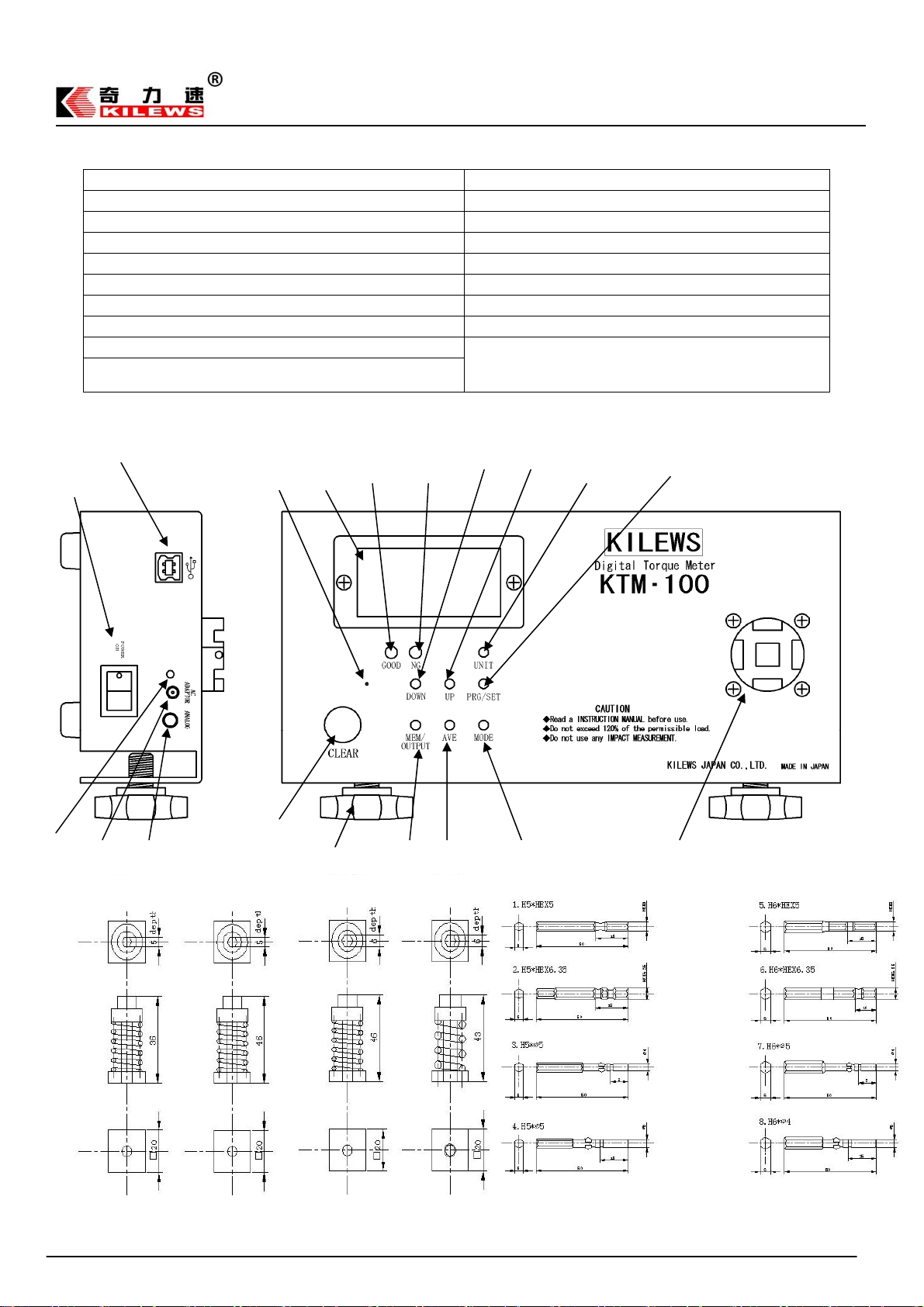
二、1 KTM-10/KTM-100 外觀
①資料輸出埠(USB ) ⑪測試底座 (SOCKET)
②電源開關 POWER SWITCH ⑫功能設定鍵 (PRG/SET)
③AC 充電孔 LED 燈 (ADAPTOR LED) ⑬單位切換開關 (UNIT SWITCH)
④AC 充電孔 (AC ADAPTOR TERMINAL) ⑭上選鍵 (UP)
⑤類比式資料輸出 (ANALOG PUTPUT TERMINAL) ⑮下選鍵 (DOWN)
⑥歸零開關 (CLEAR SWITCH) ⑯NG LED燈 (NG LED)
⑦腳座固定螺絲 (KNOB) ⑰GOOD LED 燈 (GOOD LED)
⑧查看記憶資料/資料輸出按鍵 (MEM/OUTPUT) ⑱液晶顯示器 (DISPLAY)
⑨計數平均功能鍵 (AVE) ⑲清除開關 (RESET)
⑩測量模式選擇開關 (MODE SELECT SWITCH))
2
○
○1
19
○
18
○
○17 ○16 ○15 ○14 ○13 ○12
**第一次使用此機器請於充電後按一下 RESET 開關,使機
器回覆到原廠設定**
Digital Torque Meter
3
○
6
○
4
○
5
○
SJ-10 SJ-3
7
○
○8 ○9
SJ-10K SJ-50
10
○
○11

2 KTM-50S 外觀
① 歸零開關 (RESET SW) ⑦ DC 充電孔 (DC IN)
② 電源開關 (POWER SW) ⑧ 測試底座 (SOCKET)
③ 低電量顯示 (LOBAT DISPLAY) ⑨ 腳座固定螺絲 (KNOB)
④ 液晶顯示器 (DISPLAY) ⑩ 單位切換開關 (UNIT SW)
⑤ 資料輸出埠 (DATA OUTPUT) ⑪ 測量模式選擇開關 (MODE SELECT SW)
⑥ 類比式資料輸出埠 (ANALOG OUTPUT) ⑫ 歸零調整器 (ZERO ADJUST SW)
Digital Torque Meter
J-50S
SCREW JOINT

三、1 KTM-10/KTM-100 規格:
型 號 KTM-100 (NEW) KTM-10 (NEW)
測量範圍
精度±0.5%
顯 示 器 三位元半 LCD 影像顯示
測試方向 正、反時鐘方向
P-P(PEAK)峰值模式
測量模式
電 池 配 置
使 用 扭 力 單 位
充 電 時 間
連 續 使 用 時 間
電 池 壽 命
自 動 關 機
數 據 輸 出 USB(速率19200)
專 用 充 電 器
底 座 尺 寸 20方形 和 9.5方形
機 體 尺 寸 230(L)*123(W)*65(H)
重量約1.8Kg
TRACK 變值模式
P-D(PEAK DOWN) 初值模式
Digital Torque Meter
1.5~90.0 lbf・in 0.15~9.00 lbf・in
1.5~100.0 kgf・cm 0.15~10.00 kgf・cm
0.15~10.00 N・m 0.015~1.000 N・m
顯示負荷力最高值
顯示負荷力值的變化
顯示負荷力最初峰值
電池 1.2V*5 (700mAh)
lbf・in / kgf・cm / N・m
少於 3 小時
約12小時
可充電 300 次以上,視操作情況而定
閑置 10 分鐘後 電源 OFF
輸入:AC110V or 240V
輸出:DC 12V,500mA
2 KTM-50S 規格:
測量模式
型 號 KTM-50S
0.434 ~ 43.40Lbf.in
測 量 範 圍
正 確 度
顯 示 器 三位元元半 LCD 影像顯示
測 試 方 向 正、反時鐘方向
P-P(PEAK) 峰值模式 顯示負荷力最高值 (定值 0.3 秒)
TRACK 變值模式 顯示負荷力值的變化
電 池 配 置 6VDC (Ni-Cd 1.2V x5 )
使用扭力單位 Lbf.in 、Kgf.cm 、N.m
充 電 時 間 少於8小時
連續使用時間 約 12 小時
電 池 壽 命 可充電 300 次以上,視操作情況而定
專 用 充 電 器
底 座 尺 寸 20方形 和 9.5方形
機 體 尺 寸 230(L)*123(W)*65(H)
重 量 約1.5Kg
0.5 ~ 50 Kgf.cm
0.049 ~ 4.90 N.m
200 ~ 1000 數位顯示為±0.5%
15 ~ 199 數位顯示為±1%
輸入:AC 110V or 240V
輸出:DC 7.5V(120mA)

四、KTM-10/KTM-100 設定與測量方式
4-1 MODE 模式選擇設定
請將 MODE 開關長按 1 秒以上,液晶螢幕左下角會出現 PP----PD 字樣,則表示已經進入設定模式。
若要改變測試模式請再按 MODE 開關 :即時數值(無表示)-------最高值(PP)------只顯示第一次的值(PD)。
測定模式 顯示 內容
最高值
顯示第一次值
液晶顯示 「PP」
液晶顯示 「PD」
最常用來測試電動起子的最高數值,若後面比前面數值來的
高則顯示最大的數值。
測試電動起子建議使用此模式
測試時只顯示第一次打擊數的扭力值,第二次後所有扭力皆
不顯示。
Digital Torque Meter
即時數值
液晶顯示
偵測即時反應的數值,為校正此扭力計所要用到的模式
4-2 測試單位選擇設定
UNIT 長按 1 秒以上,系統將會進入設定模式,每按一次 UNIT 開關,單位將會變換ㄧ次
Lbf.in------kgf.cm--------N.m-----(循環)
電量表示
液晶顯示 內容
充電時,請使用原廠充電器進行充電,而且將電源開關切於 off 的狀態充電。 (Input:110V or 220V;Output:12V 500m A)
4-3 功能設定鍵操作方式: 功能設定鍵方面除了本身功能鍵之外,尚須與 UP 上選鍵、DOWN 下選鍵搭配使用來設定。
設定扭力正確的範圍值
先設定扭力值得上限與下限,讓使用者可以馬上判定扭力值的偏差,例如:我們需要測試 5 kgf.cm 的扭力,我們可以設定容許的誤差範圍 0.5kgf.cm,
所以我們可以設定下限 4.5kgf.cm;上限可以設定 5.5kg.cm。
若測試的數值低於 4.5kgf.cm 或高於 5.5kgf.cm 則 NG 燈會亮,反之若在設定的範圍內,則 GOOD 會亮。
4-4 設定程序:
『1』、押 PRG/SET 鍵約 1 秒鐘,LED 綠燈會亮起即進入設定畫面,液晶顯示器會顯示 再跳至0.0,
押按DOWN鍵 ,即可設定第四位數的數值,數值變更只允許向上增加,若要增加按 UP 鍵即可。若要改變第二位數數值,再押按 DOWN 鍵
即可,如圖示:
上限值設定為 0650 為例
『2』、再押 PRG/SET ㄧ次,即可設定下限扭力值,液晶顯示器會顯示 再跳至0.0,押按DOWN鍵 。
下限值設定為 0500 為例:
『3』、再押 PRG/SET ㄧ次,即可設定 PD 的起始值,若低於設定值則將不計算。(此項只適用於 PD 模式)
PD 模式計數起始值設定為 0300 為例:
DOWN
DOWN
DOWN
電量充足,可以不用充電 電量尚有 100%
電量尚有 50%。
電量 10%,建議不要使用進行緊急充電。否則隨時會斷電的可能
電量 0%,無法開機,所以液晶顯示器無法顯示
DOWN
DOWN
DOWN
UP按6次 +DOWN
UP按5次 +DOWN
UP按3次 +DOWN
DOWN
UP 按 5 次 +DOWN
DOWN
DOWN

資
Digital Torque Meter
『4』、再 押 PRG/SET ㄧ次,設定自動歸零的時間設定 ,需要配合 UP、D O W N 設 定 ( 0.0C⇔0.1C⇔0.5C⇔1.0C⇔1.5C⇔2.0C⇔2.5C⇔3.0C⇔0.0C)
若設定為 0.0C 則為手動歸零,需要配合 CLEAR 開關歸零。
設定 1 秒自動歸零為例:
『5』、再押 PRG/SET ㄧ次,蜂鳴器的設定,UP/DOWN 選擇設定。(ON:正常聲響;OFF:全部沒有聲響;FF:只有在不糧情況下有聲響)
完成設定後
警示狀況 低於下限值 上下限值以內 超過上限值 超出扭力計的扭力
LED
蜂鳴器 斷續音 連續音 斷續音 連續音
4-5 最大值、最小值、平均值:
若想要知道測試的最大、最小、平均值可以利用此扭力計的 AVE 功能鍵來計算測試的數值(最多測試 30 組數據做運算)。
① 確認測試模式為「PP」或者「PD」,不可為 TRACK。
② 若想要此功能再作測試時必須先按一下 AVE 鍵,液晶螢幕會有「AVE」字在閃爍。
③ 測試幾次後(最多 30 次)。
④ 再按一次 AVE,則液晶螢幕毀自動秀出 計數次數----最大值(MAX)----最小值(MIN)-----平均值(AVE)。
紅色(NG)閃爍 綠色(GOOD)亮燈 紅色(NG)閃爍 紅色(NG)亮燈
UP / DOWN
UP 鍵 UP 鍵
※設定完成
PRG/SET
計數次數(最多 30 次),液晶底下無任何提示字
最大值,液晶底下會有 MAX
最小值,液晶底下會有 MIN
平均值,液晶底下會有 AVE
4-6 儲存數據、顯示、輸出
每按一次 CLEAR 按鍵會自動清除,存放在記憶位址同時如果有資料連接線(USB),也會自動輸出信號。
儲存數據
每按一次 CLEAR 按鍵,系統會自動清除數據,同時將數據保存在記憶位址中,會依照序號累增,序號從 001~800(最多可以允許儲存 800 組資料),
而系統會依照儲存順序一直累增,當超過 170 組資料時,系統會自動跳到第一組位址將數值覆蓋掉。
資料單筆刪除
可以將儲存的扭力值作刪除的動作,若將某ㄧ組儲存的值作刪除,而後面位址的數值將會往上遞補如圖示
位址 扭力值 備註
001 10.9
002 11.1
003 13.0
004 11.1
005 11.2
「1」 測試數次後,將資料儲存至記憶體
「2」 若要刪除數據,請先按 MEM/OUTPUT 按ㄧ下,液晶螢幕底下會有『MEM』字樣顯示。
「3」 配合使用 UP/DOWN 鍵來找尋位址,位址會跳『位址』與『數值』,選至『003』扭力值顯示『13.0』(大約閃爍 6 秒)。
「4」 按ㄧ下『CLEAR』鍵,螢幕會顯示 ,再按ㄧ次『CLEAR』鍵 ,表示刪除完成。後面數值會往前遞補。
位址 扭力值 備註
001 10.9
002 11.1
003 11.1 資料往前遞補
004 11.2
005 ---
測試錯誤,要將此資料刪除
料往前遞補

Digital Torque Meter
資料範圍刪除
「1」測試數次後,將資料儲存至記憶體
「2」若要刪除數據,請先按 MEM/OUTPUT 按ㄧ下,液晶螢幕底下會有『MEM』字樣顯示。
「3」配合使用 UP/DOWN 鍵來找尋位址,位址會跳『位址』與『數值』,選至『003』扭力值顯示『11.1』(大約閃爍 6 秒)。
「4」按ㄧ下『CLEAR』鍵,螢幕會顯示 。
「5」 使用 UP/DOWN 鍵來找尋位址,位址會跳『位址』與『數值』,選至『004』扭力值顯示『11.2』(大約閃爍 6 秒)。
「6」再按ㄧ次『CLEAR』鍵 ,表示刪除完成。後面數值會往前遞補。
※設定完成
資料輸出
「1」 先按 MEM/OUTPUT,螢幕底部會顯示 MEM 字樣,而且會顯示最後一筆儲存的數據。
「2」 再按ㄧ次MEM/OUTPUT,螢幕會顯示 ,選擇要輸出數據的起始位址,例如第 005 筆數據,按 UP/DOWN 鍵選擇『005』。
「3」 再按ㄧ次MEM/OUTPUT,螢幕會顯示 ,選擇要輸出數據的結束位址,例如第 070 筆數據,按 UP/DOWN 鍵選擇『070』。
CLEAR 鍵 UP / DOWN 鍵 UP / DOWN 鍵 CLEAR 鍵
「4」 再按ㄧ次MEM/OUTPUT,螢幕會顯示 ,即表示已經將 005~070 位址的數據已經輸出至 USB。
MEM/OUTPUT MEM/OUTPUT
UP / DOWN
MEM/OUTPUT
UP / DOWN
※ 設定完成
CAUTION
新款KTM-10/KTM-100 本身帶有暫存記憶體,在完全沒電的情況下長時間不使用,機器將會自動清除
暫存的資料,而且下次充電後開機必須重新按 ”RESET” 方可正常開機,所以使用者必須適時注意扭力
計電池的電量,或者定期將內存資料導出,以免因疏忽而造成資料的流失。

Digital Torque Meter
五、準備與測量方法
5-1 安裝
(1)測量儀器在測量較大扭力時可能會揮動起來。因此測量儀器必須用穩固的腳座器具來固定它。
(2)KTM-50S 只能測試本公司產品半自動型號
例如: SK-205LS;SK-215LS;SK-2125LS;SK-2135LS;SK-2145LS;SK-2205LS;SK2215LS;SK-2225LS;SK-2235LS
SK-2245LS
TKS-1300LS;TKS-1500LS;TKS-2500LS;TKS-3500LS;TKS-4500LS;TKS-2500LSF
BSD-1000LS;BSD-1200LS;BSD-101;BSD-102
(3)KTM-10;KTM-100 皆可以測試電動起子全自動型號的扭力;但是必需慎選測試彈簧座(SJ)
5-2 測量模式的設定
有以下 3 種模式可供選擇。(KTM-50S 只有 P-P、TRACK)
(1) P-P(PEAK) 峰值模式:顯示測量到的最大扭力值。
(2) TRACK 變值模式:顯示即時的扭力值。
(3) P-D(PEAK DOWN) 初值模式:顯示第一個峰值。
5-3 測量方式
(1) 歸零調整: 打開扭力計電源,再將測量模式切換到”TRACK”,此時顯示器的數值應為零。若不是零則
按”歸零開關”將數值歸零,接著將測量模式切換為”PEAK 或 P-P” 。
(2) 準備好受測工具並銜接,並開始測量扭力。
(3) 測量時應順時針完全鎖緊或工具自行停止或跳脫為止。
(4) 當測量完成後,顯示器上的數值就是該次測量的扭力值。
(5) 如果要再進行測量,再次測量前按”歸零開關”將顯示器的資料清除。
(6) 儀器在連續 10 分鐘未使用的情況下,將會自動關機(KTM-50S 無此功能)。
(7) 若使用者需要測量扭力變化可切至 TRACK 變值模式
六、充電
當顯示器上出現”LOBAT”字樣時表示扭力計電量不足,需進行充電。
請關閉扭力計電源,以隨機配備的充電器,接妥正確電源與扭力計充電孔即可進行充電。
充電時間請勿超過 8 小時,以免造成電池過熱、漏液甚至燃燒等傷害。
七、資料傳輸(只限 PEAK 模式)
資料傳輸(需搭配專用傳輸線與軟體) : 在每次測量完畢按歸零開關時(或機器自動歸零時),扭力計會自動將測
得的資料經傳輸裝置輸出到電腦上。
※ 搭配用的傳輸裝置為選購產品;扭力測試儀必須切於 PEAK 模式;TRACK 模式無法抓取正確扭力數值。
八、服務保證
本產品在購買後一年內若有因生產或運送過程瑕疵而產生的故障情況,本公司無條件提供修理服務;但下情
況則被排除在外:
◎ 不當使用、修理或重組儀器而導致故障者。
◎ 在購買後因摔落等事故而導致故障者。
◎ 因天然災害、污染和不正常的電壓所導致的故障。
九、校正服務
本產品於出廠前皆已做過可靠且符合國際標準的準確度校正,但為維持扭力計的精確度,應將扭力計做定期
的校驗。本公司另提供專業並符合標準的調修服務,唯保證期間外的校驗服務得另收費用。

十、 電動起子與扭力計
1.電動起子之扭力調整
a. 旋轉扭力調整環以增加或減少扭力輸出。
順時針方向調至較高刻度,代表增加扭力;逆時針方向調至較低刻度,代表減少扭力。
b. 操作電動起子時應循序漸進,先操作小扭力試鎖螺絲,若感覺扭力不足再漸漸調高扭力。
c. 電動起子的扭力輸出和扭力刻度的相互關係可參考說明書內的”扭力曲線圖”。
鎖緊螺絲之扭力大小取決於螺絲本身之型式、材質尺寸及其鉚合物之材質。
d.當被鎖物件鎖附完成時,視其符合品質標準後,再用扭力計測量該電動起子的正確扭力,若鎖附狀況未達標準,
則調整電動起子扭力,直到符合標準為止。
e. 電動起子用扭力計測量並記錄好扭力後,將起子外殼前鎖環旋開,換上扭力固定環,如此可以防止異常的扭
力變動。
2、扭力計的使用方法(工具:扭力計、全自動電動起子)
a. 根據螺絲鎖附所需要的扭力選擇適當的電動起子型號,
可參考電動起子目錄或電動起子向量圖表
Digital Torque Meter
b. 選擇合適的扭力計: KTM-10 最大可測扭力為 10Kgf-cm,KTM-100 可測最大扭力為 100 Kgf-cm;選擇扭力計彈
簧座(依欲測試的扭力為准可分為 4 種,請參考以下表格)。
使用範圍(Kgf-cm) 扭力計 彈簧座 備註
3.0 以下 KTM-10 SJ-3 最大可測 3Kgf-cm
3.0~10.0
10.0~50.0 KTM-100 SJ-50 最大可測 50Kgf-cm
0.5~50S KTM-50S J-50S
c. 測試步驟:
打開電源開關。
測量模式(MODE)設定為“TRACK”。
單位切換開關設定為欲測試的單位(Lbf-in;Kgf-cm;N-m)。
d. 歸零調整: 檢視顯示器數值是否為歸零狀態,若不是則按歸零開關(CLEAR),使顯示歸零(KTM-50S 需調整歸
零調整器 ZERO.ADJ)。
e. 測量模式(MODE)設定為“ PEAK”。
f. 電動起子套上接杆,另一端則置於彈簧座接頭端,啟動電動起子開始測量電動起子輸出扭力。
KTM-10 SJ-10
KTM-100 SJ-10K
最大可測 10Kgf-cm
最大可測 50Kgf-cm
半自動起子專用
g. 當數值顯示後即表示電動起子測量正常與完成;顯示器上的數值就是電動起子輸出扭力值。
h. 完成電動起子測定後,需反轉放鬆彈簧座,以防止彈簧座彈性疲乏,按歸零開關清除螢幕後即可繼續測量
(KTM-50S 不需要鬆開彈簧座,測試方式以直接打擊為主)。
i. 使用同一把電動起子於不同廠牌型號的扭力計(或扭力計彈簧座)會產生不同的扭力值誤差,其誤差來源多為
彈簧座的彈簧特性不同所致。同一工作場所有兩台以上的扭力計時,使用單位應定期校驗扭力計並比對其彈
簧座的彈簧特性差異是否過大,若差異過大則應替換新的彈簧或整組彈簧座。
j. 使用扭力計時請勿同時進行充電,以免影響測試資料的準確性。
如有任何疑問 請與當地代理商聯繫 !

Digital Torque Meter
Operation Manual for Digital Torque Meter
Model: KTM-100 KTM-10
1.Caution for safety
1. Keep work area always clean.
Cluttered areas and benches may invite injuries.
2. Consider work area environment.
Do not use torque meter in the rain or in the damp or wet place.
Use the product at a place left at constant temperature(about 24℃).
Keep work place well lighted.
Do not use or charge the product in presence of flammable liquids or gases.
3. Keep children away.
Keep any person other than the operator(s) away from work area.
4. Dress properly.
Do not wear loose clothing or jewelry, which may be caught in moving parts.
5. Work with the most care.
When using the product, carefully work, with consideration to how to handle, how to work, work environment, etc.
6. Fix main body firmly.
When operated for measuring a large torque, use clamps or a vise, etc. ,It is not only more safe than holding by hand
but also makes it possible to grip the screwdriver by both hands.
7. Do not apply a torque exceeding the permissible load.
If applied beyond the permissible load, it may cause damage to the detector, resulting in accident or injury.
8. Do not disassembly, shock and vibrate this product.
Avoid disassembling the product that is a precise instrument. If the torque meter is damaged by excessive shock or
vibration, the product may not only show the full performance but also result in accident or injury.
9. Caution to electric shock
Do not touch power plug by wet hand. It may cause electricshock.
10. For charging the battery be sure to use only exclusive charger.
Using a charger other than specified may cause a fire or injury.
11. Charge properly.
Charge on the indicated voltage. Do not use DC power or engine generator. It may cause abnormal heat, resulting in
a fire.
Keep the charging time not longer than 8 hours. Overcharge may bursting, overheat and liquid leakage, resulting in a
fire or injury.
Charge in a well-ventilated place. While being charged, do not cover with cloth.
12. Never throw the battery(built-in the torque meter) into fire.
It may cause burst or give off toxic substance. (The procedure for scrapping the battery shall be followed in
accordance with local or regional law on waste disposal. If there is no local or regional law on waste disposal, be
sure to dispose of the battery at a recycling shop.)
13. In the following cases, turn off the main switch and disconnect the plug from outlet.
When not used or charged;
When repaired;
When any other danger is expected.
14. Maintain torque meter with care.
For better and safer performance, check screw joints regularly and use ones whose tips are free from deformation
and wear down.
For replacement of accessories follow the instruction manual.
Inspect cords and extension cords periodically and if damaged, replace them.
15. Do not handle cord violently.
Do not carry the product hanging by cord or draw out socket from outlet by pulling cord.
Do not put cord near to a hot, oily or edgy part.
16. Check for absence of damaged parts.
Before further use of the product, carefully check for no damage, normal operation, or intended functions.
Check whether or not any other components that may affect its operation are normal.
Replace parts according to the instruction manual.

Digital Torque Meter
17. Have the product repaired by the specialized dealer.
Do not modify this product.
Repair should be made always by the dealer where you purchased the product. If repaired by any person with no
knowledge or skills of repair, it may not only show the full performance but also may cause any accident or injury.
18. Use only the specified accessories and attachments.
Do not use any accessories and attachments other than ones specified in this instruction manual.
19. Store properly when not in use.
Store the torque meter in a dry place and in a height out of children’s reach, or secured area.
To transport the product, reuse the packing case with which this product was delivered.
20.SJ need be lubricated by attached lubrication. Torque test will become unstable if lubrication is neglected quite a
awhile
2、Appearance KTM-10/KTM-100
① USB ⑪ SOCKET
② POWER SWITCH ⑫ PRG/SET
③ AC ADAPTOR LED ⑬ UNIT SWITCH
④ AC ADAPTOR TERMINAL ⑭ UP
⑤ ANALOG PUTPUT TERMINAL ⑮ DOWN
⑥ CLEAR SWITCH ⑯ NG LED
⑦ KNOB ⑰ GOOD LED
⑧ MEM/OUTPUT ⑱ DISPLAY
⑨ AVE
⑩ MODE SELECT SWITCH
1
○
19
SJ-10 SJ-3 SJ-10K SJ-50
18
○
○
17
○
16
○
Digital Torque Meter
⑲ RESET **Pease press “RESET” button after
charging the device at the first time which allows the
12
○
○
device recovering to original setting.**
15
○
14
○
10
○
○11
13

Digital Torque Meter
2. Appearance KTM-50S
(1) RESET SWITCH (7)AC ADAPTOR TERMINAL
(2) POWER SWITCH (8) SOCKET
(3) LOBAT DISPLAY (9) KNOB
(4) DISPLAY (10) UNIT SWITCH
(5) DATA OUTPUT TERMINAL (11) MODE SELECT SWITCH
(6) ANALOG OUTPUT TERMINAL (12) ZERO ADJUST 【KTM-50S ONLY】
SCREW JOINT
J-50S

3. Specifications
3-1 KTM-10/ KTM-100
MODEL KTM-100 KTM-10
Measuring range
Accuracy
Display 3.5 figures of LCD
Measuring direction CW・CCW
Measurement
mode 3 way
Data transfer USB1.0 (Baud rate:19200)
Power supply
Measuring unit lbf・in-kgf・cm-N・m (selectable)
Charging time From empty – 8hours
Continuous working time About 12hours
Battery life
Exclusive charger
Socket size 20mm square and 9.5mm square
Size 230(L) * 123(W) * 65(H)
Weight About 1 kg
3-2 KTM-50S
MODEL KTM-50S
Measuring range
Accuracy
Display 3.5 figures of LCD
Measuring direction CW・CCW
Measurement
mode 3 way
Data transfer Serial interface RS232C (Baud rate:9600)
Power supply
Measuring unit lbf・in - kgf・cm - N・m (selectable)
Charging time From empty – 8hours
Continuous working time About 12hours
Battery life
Exclusive charger
Socket size 20mm square and 9.5mm square
Size 230(L) * 123(W) * 65(H)
Weight About 1 kg
Digital Torque Meter
1.5~90.0 lbf・in 0.15~9.00 lbf・in
1.5~100.0 Kgf・cm 0.15~10.00 Kgf・cm
0.15~10.00 N・m 0.015~1.000 N・m
From 200~1000 digit display within +/- 0.5%
From 15~199 digit display within +/-1digit
P-P (peak) Peak load value hold.
TRACK Indication of real time torque value.
P-D (peak down) Indication peak down point and hold.
6 VDC (Ni-Cd chargeable battery
1.2V×5cells )
Chargeable for 300 times or more. However,
it varies depending on operating conditions.
INPUT:110V or 240V 60Hz
OUTPUT:DC 12V 500mA
*Do not use for measurement of impact tool. Do not apply more than the specified torque.
0.43~43.40 lbf・in
0.5~50.0 Kgf・cm
0.05~4.90 N・m
From 200~1000 digit display within +/- 0.5%
From 15~199 digit display within +/-1digit
P-P (peak) Peak load value hold.
TRACK Indication of real time torque value.
6 VDC (Ni-Cd chargeable battery
1.2V×5cells )
Chargeable for 300 times or more. However,
it varies depending on operating conditions.
INPUT:110V or 240V 60Hz
OUTPUT:DC 7.5V 120mA

Digital Torque Meter
4. Setting and measuring mode For KTM-100/KTM-10
Mode setting
Press the MODE key over one second. It means getting into setting mode when the words
PP----PD Shown on the below left on LCD screen.
Please press the MODE key if needing to change measuring mode :
immediate value (no indication)-------maximum value (PP)------only indicating the first value (PD).
Measuring mode Display Contents
The maximum value is often to be used for electric screwdriver
test. It will display the maximum value if the following value is higher
than previous value.
This mode is recommended for electric screwdriver test.
It only indicates torque value of the first hit. The rest of torque
values will not be indicated.
Detecting the immediate value.
Maximum value
Indicating the first
value
Immediate value
「PP」displaying on LCD
「PD」displaying on LCD
displaying on LCD
Test unit selection
Press UNIT key over one second, the system will get into setting mode. The unit will change whenever user press
UNIT key. Lbf.in -------------kgf.cm------------N.m ---------------(cycle)
Power capacity indication
Displaying on
LCD
Sufficient power capacity, no need to recharge, the power capacity is still 100% left.
The power capacity is still 50% left.
It is not allowed to use urgent charge when the power capacity is 10% left. Because the
power will be shut off anytime.
The power cannot be on when the power capacity is 0% left. LCD will be not working
also.
Contents
Please use original charger and turn off the power when charging. (input: 110V or 220V; output: 12V 500m A)
The operation of functional setting key: The operation of functional setting key should collocate with UP key
and DOWN key to operate the function except its own function.
Setting proper value range of torque
First of all, setting the torque value both minimum limit and maximum limit, so that user can judge
the difference of torque value. For example : We need to test 5kgf.cm torque. We can set a tolerated
range 0.5kgf.cm, so we can set minimum limit with 4.5kgf.c m; maximum limit with 5.5kgf.cm
If the test value less is than 4..5kgf.cm or higher than 5.5kgf.cm, the NG light will be on. On the other hand, the GOOD
light will be on if the setting is within the range.
Setting procedure :
『1』 press PRG/SET key approximately one second, green LED light will be on and getting into set screen. LED
monitor will display “ ” and jump to 0.0.
Press DOWN key, then the value of fourth digit can be set. The change of value is only allowed to increase. If needing
increase, press UP key. If changing second digit, please press DOWN key shown
as following draw:

Digital Torque Meter
FOR EXAMPLE
Setting maximum limit as 0650
『2』 press PRG/SET once again, setting torque value of minimum limit, LCD will display “ ” and jump to 0.0
again, press again DOWN key
DOWN DOWN
UP 6 Time DOWN DOWN UP 5Time
Setting minimum limit as 0500:
DOWN DOWN
UP 5 Time
『3』 press PRG/SET once again, set the initial value of PD, if the initial value is less than set value, the value will
not be recorded. (It is only applying to PD mode)
DOWN DOWN
Setting the PD mode initial value as 0300:
『4』 press PRG/SET once again, set clear switch with “ ” and needing to match UP, DOWN.
It is set by hand if 0.0C set(0.0C⇔0.1C⇔0.5C⇔1.0C⇔1.5C⇔2.0C⇔2.5C⇔3.0C⇔0.0C); matching CLEAR key also.
DOWN DOWN
UP 3 Time
DOWN DOWN
Setting clear with one second:
『5』 press PRG/SET once again, setting buzzer, UP/DOWN setting. ( ON: normal sound, OFF: no sound, FF: sound
comes only under abnormal situation)
UP /DOWN
※SETING OK
UP UP
PRG/SET
After setting
Alarm Less than minimum value
LED
buzzer
Red blink (NG) Green light (Good) Red blink (NG) Red light (NG)
Interrupted sound Continuous sound Interrupted sound Continuous sound
Between minimum value
and maximum value
Over maximum value Excess torque
※Maximum Value, minimum value, average value
We can take advantage of the AVE key to test maximum value, minimum value and average value. ( you can test at most 30 datum).
1. Be sure the test mode is 『PP』or 『PD』, not TRACK.
2. Press AVE key to make re-testing, the 『AVE』will blink on the LCD.
3. After several tests (at most 30 numbers)
4. Press AVE again, the LCD will automatically display the counting numbers –MAX –MIN—AVE.
The counting numbers (at most 30 numbers), there is no any indicating on the LCD.
MAX Max, 0.650. will be shown on the LCD.
MIN Min, 0.500, will be shown on the LCD
AVE Ave, 0.600, will be shown bon the LCD
Data saving, display, output
Whenever pressing, CLEAR key will automatically clear and save memory.. At the same time signal will
automatically output if USB is used.
Data saving
Whenever press CLEAR key, the system will automatically clear the data., meanwhile, the data will be saved in

Digital Torque Meter
the memory according to serial number. The serial number is from 001 ~ 800 (no more than 800 datum) and the
first data will be automatically covered as new data is over 170
th.
Deleting the single data
Torque value can be deleted. The value of following will move ahead.
SITE VALUE Remark
001 10.9
002 11.1
003 13.0 Press “clear” to remove this value
004 11.1
005 11.2
「1」 Several tests later, datum will be kept in memory.
「2」 Please press the MEM / OUTPUT key when deleting the data is necessary. The 「MEM」
will appear on the LCD.
「3」 Taking advantage of UP/DOWN key searching for site, LED will display “site” and “value”, the
torque value will be 「13.0」( blinking around 6 seconds) when choosing 「003」.
「4」 Press 「CLEAR」key, “ ” will show on the LCD, press CLEAR key again,
delete is completed. The following value will move ahead.
SITE VALUE Remark
001 10.9
002 11.1
003 11.1 The following value will move ahead
004 11.2 The following value will move ahead
005 ---
Delete the data range
「1」 Several tests later, datum will be kept in memory.
「2」Please press the MEM / OUTPUT key when deleting the data is necessary. The 「MEM」will appear on the LCD.
「3」Taking advantage of UP/DOWN key searching for site, LED will display “site” and “value”, the torque value will be
「11.1」( blinking around 6 seconds) when choosing 「003」.
「4」Press 「CLEAR」key, “ ” will show on the LCD
「5」Taking advantage of UP/DOWN key searching for site, LED will display “site” and “value”, the torque value will be
「11.2」( blinking around 6 seconds) when choosing 「004」
「6」 Press the 「CLEAR」key again , delete is completed. The following value will move ahead.
UP /DOWN CLEAR UP /DOWN CLEAR
※SETING OK
Data output
「1」 Press MEM/OUTPUT first, LCD will display “MEM” and the last data is shown also.
「2」 Press MEM/OUTPUT again, LCD screen will display “ ”, choosing the initial site of output data. For
example, the 005 data, press UP/DOWN key to choose 「005」.
「3」 Press MEM/OUTPUT again, LCD screen will display “ ”, choosing the ending site of output
data. For example, the 070 data, press UP/DOWN key to choose 「070」.
「4」 Press MEM/OUTPUT again, LCD will display “ ”, means sites 005~070 have been output to USB.
MEM/OUTPUT MEM/OUTPUT
UP /DOWN
MEM/OUTPUT UP /DOWN
※SETING OK

Digital Torque Meter
5. Preparation and the measuring method
5.1 Installation
A measuring instrument may be brandished at the time of measurement of a large torque.
Surely, a measuring instrument should use a fixed knob etc. and fix it firmly.
5.2 A setup in the measurement mode
The 3 following modes can be chosen with the setting. (It unites with the use purpose
and please choose.)
(1) PP (peak measurement) : The maximum under measurement is always displayed.
(2) TRACK (track measurement) : The value of the load torque concerning the detection machine is displayed as it is.
(3) PD (peakdown measurement) : Value when load torque value changes from a rise to descent is displayed.
Carry out after pushing a CLEAR button at once when applying re-load.
*PD and PP measurement operates from 10 or more numerical values.
5.3 Measuring method
(1) Check that the display part is zero at the time of power supply ON. If display is not show as zero,set a measurement mode
select switch to TRACK, push CLEAR button,and set it as back PP which performed zero adjustment.
(2) The bit of screwdriver to measure among the screw part of screw joint is set firmly, and screwdriver is started.
(3)It checks that operation of screwdriver has been completed normally, the measurement torque value of a display part is read,
and it becomes a measurement end.
(4) After a measurement end, if CLEAR button is pushed, a display will be cleared by zero.When continuing measurement, it
repeats from (1) again.
(5) Choose the TRACK mode , if real time torque value want to be measured
6. Power supply
If this measuring instrument is left 10 minutes or more or battery capacity stops being sufficient, a power supply is turned off
automatically.
If battery capacity decreases, since LOBAT will be displayed, charge by inserting the connector of an exclusive charger in an AC
ADAPTOR terminal.
The fully charge is in the state which turned OFF the power supply switch, and takes about 8 hours.(Do not perform charge of 8
hours or more. It may become the cause of the fire by a burst of a battery, generation of heat, and liquid leak, or an injury by fault
charge.)
Moreover, when turning off a power supply, a power supply SW is pushed for about 1 second.
7. Date transfer (PEAK Mode Only)
7.1 Date format
Data transfer is RS-232C output conformity. Data can be outputted to the printer corresponding to RS-232C, or a personal
computer etc.
Spec. Data bit length Start bit 1 + data bit 8 + stop bit 2 + NO parity
Baud rate 9600bps
Connector form D-Sub-9pin
Connector spec. No. 3 pin:Data output / No. 5 pin:GND
18
CAN
CAN : Cancellation
※ : Case in the memory mode Number of samples ・ Usually case in the mode Space
SO : Double width expansion printing specification
+/- : Measurement mark + the direction of bolting ・ - return direction
Measured value : A decimal point is also included.
The last is a space when there is no decimal point.
1 0 . 0 0 → 10.00 SI.
OE 20
○○○
※
SO Space Mark
+/-
○○○○○
Measured
value Space SI Unit
20 OF
All data 21
○○○○○○
OD
CR

Digital Torque Meter
SI : Double width expansion printing release
Unit : In the case of N・m etc., the remainder space
N ・ m → N・m ( k g f ・ c m → kgf・cm )
CR : Carriage return
△cautions An interface cable is used for connection of a computer.
Unite with a computer and prepare a cable.
Please inquire about a cable of a dealer where you purchased the product.
7.2 Output method of data
Data is outputted whenever it pushes CLEAR key after a measurement end.
Date output of the time of use of an date clear function is automatically carried out in setting time.
8. Guarantee
It is allowed to fix gratuitously, if the fault which will originate in manufacture, ransportation, etc. of our company within one year
after a purchase should occur, although product was manufactured under sufficient quality control.
In the following case, it becomes the charge also within a guarantee term.
Failure by the error, and unjust repair and unjust reconstruction and damage on use
Failure by fall etc. and damage after a purchase
Failure by the natural disaster, pollution, and unusual voltage, and damage
9. Calibration trust service
Periodical calibration is required in order to manage the accuracy of torque meter. By our
company, the calibration with the high reliability traced to the national standard is performed, and in order to use it within accuracy,
I recommend you calibration of one year. I offer an result of calibration document, a certification on calibration, and a traceability
system figure by demand. (Periodical calibration is a charge.)
Documents appended at the time of product purchase
Result of calibration document
Certification on calibration document
Traceability system figure
The cautions on use
* Please do not apply the load more than the measurement range by any means.
* Attached grease is attached to the bolt or the bearing part, please check before use.
* Where a spring is loosened, please be sure to keep after use.
The number of times of an exchange standard is about 2500 times.
When the following condition comes out, please stop use, and use new joint.
When there is bend and wear of a screw thread
When there is sound etc.
The new model KTM-10/KTM-100 itself has temporary memory. The memory will be cleared automatically once the
machine is not used for a long time. Moreover it is necessary to press “Reset” button after full-charged, then it can be on
normally. The user should pay attention to the battery status or save data periodically for keeping memory from losing..
CAUTION

Digital Torque Meter
10. Electric Screwdriver & Torque Meter
1、T orque adjustment for Electric Screwdriver
A、
Turn the Torque Adjusting Ring to increase or decrease the torque output. Adjust clockwise to higher scale means
torque increase; anti-clockwise to lower scale means torque decrease.
B、Operate electric screwdriver should be step by step in proper sequence, first run with a small torque to fasten the
screw, if feel not enough torque, then adjust to higher torque gradually.
C、 The mutual relation between torque output and scale, please refer to the “Torque Range Chart” on the instruction.
The correct torque adjustment of fastening screws rely on screws type, material, size and the object material of
being screwed.
D、When object has been done screw-fastening, see if it meets the standard of quality, then measure the right
torque value by Torque Meter, if the screw fastening situation is not yet to reach standard, adjust the torque from
electric screwdriver until meets the standard.
E、Record the torque value with Torque Meter for electric screwdriver, and turn open the front clamping ring of
electric screwdriver’s housing, then exchange Torque Fixing Ring to prevent from exceptional torque change.
2、Torque Meter Operating Method (Tools: Torque Meter, Automatic Electric Screwdriver)
A、Choose a proper electric screwdriver type in accordance with the required torque of screw-fastening. Please
consult with electric screwdriver catalogue or vector chart of electric screwdriver
B、Choose a proper Torque Meter: KTM-10 can be measured torque at maximum 10Kgf-cm ; KTM-100 can be
measured torque at maximum 100 Kgf-cm; select the Spring Jack (According to the basis of requiring torque
measurement which can be parted with 3 items as following tables:
Torque Range(Kgf-cm) Torque Meter Spring Joint Remark
3.0 以下
3.0~10.0
KTM-10 SJ-3
KTM-10 SJ-10
KTM-100 SJ-10K
10.0~50.0 KTM-100 SJ-50
0.5~50S KTM-50S J-50S
C、Test procedures:
Switch on the power
Set Measure Mode (MODE) to “TRACK”
Unit Switch sets to required measurement of unit.(Lbf-in;Kgf-cm;N-m)
D、Reset adjustment: Check the value on LED display if is at zero status, if not then press Reset button (CLEAR) to display 0.0
、Set the Measuring Mode (MODE) to “PEAK”.
E
F、Cover with connecting pole of Spring Jack on the electric screwdriver, put another end of connecting pole in the
head terminal of Spring Jack, power on the electric screwdriver and start to measure output torque of the electric
screwdriver.
G、When torque value has been indicated, it means functional measurement for electric screwdriver is normal and
accomplished; the value indicates on LED display is the output torque value of electric screwdriver.
H、After finishing the measurement of electric screwdriver, reverse to loose Spring Jack for keeping from springiness
fatigue.
I、Use the same electric screwdriver on different brands of Torque Meters (or Spring Jacks) could result in different
torque value inaccuracy, such inaccuracy comes mostly from different spring character of Spring Jack. If there
are two sets or more Torque Meters using on the work site, responsible department should examine Torque
Meters periodically and check the gap of spring character among those Spring Jacks whether too large, if the
answer is yes, then need to change a new spring or the whole set of Spring Joint.
J、Please note while using Torque Meter, don’t charge the battery at the same time in order to avoid affecting the
accuracy of test data.
Max measurable
3Kgf-cm
Max measurable
10Kgf-cm
Max measurable
50Kgf-cm
Max measurable
50Kgf-cm
Semi-Automatic tools
For any inquiry, please contact your dealer !
 Loading...