

Kilews BSD-3000L, BSD-3200L, BSD-3300L, BSD-6200L, BSD-6600L Operation And Maintenance Manual
...
®
OPERATION AND MAINTENANCE MANUAL
LOW VOLTAGE
METAL ASSEMBLY SCREW DRIVER
WWW.KILEWS.COM.CN
KILEWS ELECTRIC TOOLS(SHANGHAI)CO., LTD.
No.367, 2nd Xinjian Road, Xuhang Town, Jiading District, Shanghai 201808 China
Tel: 86-21-59556022 Fax: 86-21-59553779
OSH-D07E
BSD-3000L
BSD-3200L
BSD-3300L
BSD-6200L
BSD-6600L
BSD-6600LF
BSD-8000L
BSD-8200L
BSD-8800L
BSD-8800LF

BSD-3000 Series
Metal Assembly Screwdrivers are designed for installing threaded fasteners in light
industrial and appliance manufacturing applications.
KILEWS is not responsible for customer modification of tools for applications on which
KILEWS was not consulted.
Important safety information enclosed.
Read all these instructions before placing tool in service or operation this tool and save
these instructions. It is the responsibility of the employer to place the information in this
manual into the hands of the operator. Failure to observe the following warnings could
result in injury. When using electric tools, Basic safety precautions should always be
followed to reduce the risk of fire, electric shock and personal injury, including the
following:
1. General Safety Rules
2. Operations Cautions
3. Specifications
4. Description Of Operation
5. Torque Adjustment Operation
6. Accessories
7. Servicing
NOTICE
WARNING

BSD-3000 Series
WARNING!
Read all instructions Failure to follow all instructions listed below may result
in electric shock fire and/or serious injure. The term “power tool” in all of the warning listed
below refer to your mains operated (corded) power tool or battery operated (cordless)
power tool.
SAVE THESE INSTRUCTIONS
1) Electrical Safety
a) Keep work area clean and well lit. Cluttered and dark areas invite accidents.
b) Do not operate power tools in explosive atmosphere, such as in the presence of
flammable liquids, gases or dust. Power tools creat sparks which may ignite the dust
of fumes..
c) Keep children, and bystanders away while operating a power tool. Distractions can
cause you to lose control.
2) Electrical Safety
a) Power tool plugs must match the outlet. Never modify the plug in any way. Do not
use any adapter plugs with earthed (grounded) power tools. Unmodified plugs and
matching outlets will reduce risk of electric shock.
b) Avoid body contact with earthed or grounded surfaces such as pipes, radiators,
ranges and refrigerators. There is an increased risk of electric shock if your body is
earthed or grounded.
c) Don’t expose power tools to rain or wet conditions. Water entering a power tool will
increase the risk of electric shock.
d) Do not abuse the cord. Never use the cord to carrying, pulling or unplugging the
power tool. Keep cord away from heat, oil, sharp edges or moving parts. Damaged
or entangled cords increase the risk of electric shock.
e) When operating a power tool outdoors, use an extension cord suitable for
outdoor use.Use of cord suitable for outdoor use reduces the risk of electric shock .
3) Personal Safety
a) Stay alert, watch what you are doing and use common sense when operating a
power tool. Do not use power tool while you are tired or under the influence of
drugs, alcohol, or medication. A moment of inattention while operating power tools
may result in serious personal injury.
b) Use safety equipment. Always wear eye protection. Safety equipment such as dust
mask, non-skid safety shoes, hard hat, or hearing protection used for appropriate
conditions will reduce personal injuries.
c) Avoid accidental starting. Ensure the switch is in the off position before plugging
in. Carrying power tools with your finger on the switch or plugging in power tools that
have the switch on invites accidents.
d) Remove any adjusting keys or wrench before turning the power tool on. A wrench
or a key that is left attached to a rotating part of the power tool may result in personal
injury.
e) Do not overreach. Keep proper footing and balance at all times. This enables better
control of the power tool in unexpected situations.
f) Dress properly. Do not wear loose clothing or jewellery. Keep your hair,clothing,
and gloves away from moving parts. Loose clothes, jewellery, or long hair can be
caught in moving parts
1. General Safety Rules

BSD-3000 Series
g) If devices are provided for the connection of dust extraction and collection
facilitys, ensure these are connected and properly used. Use of these devices can
reduce dust related hazards.
4) Power tool Use and Care
a) Do not force the power tool. Use the correct power tool for your application. The
correct power tool will do the job better and safer at the rate for which it was designed.
b) Do not use power tool if switch does not turn it on or off. Any power tool that
cannot be controlled with the switch is dangerous and must be repaired.
c) Disconnect the plug from the power source before making any adjustments,
changing accessories, or storing the power tools. Such preventive safety measures
reduce the risk of starting the power tool accidentally.
d) Store idle power tools out of reach of children and do not allow persons
unfamiliar with the power tool or these instructions to operate the power tool.
Power tools are dangerous in the hands of untrained users.
e) Maintain power tools. Check for misalignment or binding of moving parts,
breakage of parts and any other condition that may affect the power tools
operation. If damaged, have the power tool repaired before use. Many accidents are
cause by poorly maintained power tools.
f) Keep cutting tools sharp and clean, Properly maintained cutting tools with sharp
cutting edges are less likely to bind and are easier to control.
g) Use the power tools, accessories and tool bits ect., in accordance with these
instructions and in the manner intended for the particular type of power tool,
taking into account the working conditions and the work to be performed. Use of
the power tool for operations different from intended could result in a hazardous
situation.
5) SERVICE
a) Have your power tool serviced by qualified repair person using only indentical
replacement parts, This will ensure that the safety of the power tool is maintained.
Additional information shall be provide
a) Instruction for putting into use
1. Setting-up or fixing power tool in a stable position as appropriate for power tools which
can be mounted on a support.
2. Assembly
3. Connection to power supply, cabling, fusing, socket type and earthing requirements.
4. Illustrated description of functions.
5. Limitations on ambient conditions.
6. List of contents.
b) Operating Instructions.
1. Setting and testing.
2. Tool changing.
3. Clamping of work.
4. Limits on size of work piece.
5. General instructions for use.
c) Maintenance and servicing.
1. Regular cleaning, maintenance, and lubrication.
2. Servicing by manufacture or agent, list of addresses.
3. List of user-replaceable parts.
4. Special tools which may be required.

BSD-3000 Series
1) Whenever changing a bit, make certain the Forward / Reverse Switch is in the “ OFF
“ position and tool is unplugged.
2) Do not allow chemicals such as acetone, benzene, thinner, trichloroethylene ketone, or
other similar chemicals to come in contact with the screwdriver housing as damage
will result.
3) Do not drop or abuse the screwdriver.
4) Do not adjust the torque setting higher than 8 on the torque scale.
5) There should be a tool rest interval when cycles three seconds or longer. This tool is
intended for a duty cycle of 0.8 sec on, 2.4 sec off.
6) Do not use this screwdriver for tightening wood screws. This is “ Metal Assembly
Screw Driver ”
7) Do not operate the Forward / Reverse Switch the motor is running.
8) Whenever a tool is not being used, move the Forward / Reverse Switch to the “OFF”
position and unplug the screwdriver.
● Do not drop or abuse the tool.
● Whenever a tool is not being used, position the Power Switch to the “OFF” position
and unplug the power cord.
2. Operations Cautions
CAUTION

BSD-3000 Series
REQUIREMENTS
This tool requires an power controller BSP-32HL-40W( input:220VAC 50/60HZ output:24/32VDC)
BSP-32VR-40W(input:220VAC 50/60HZ output:24-32VDC)
BSP-32HL-60W(input:100-240VAC 50/60HZ output:24/32VDC)
BSP-32VR-60W(input:100-240VAC 50/60HZ output:24-32VDC)
DATA 1:
MODEL
BSD-3000L BSD-3200L BSD-3300L
Input voltage(DC)
32VDC
Rated input
25W
Bit torque
Kgf.cm
0.3-3.5 0.6-7 1-10
Lbf.in
0.26-3.01 0.53-6.10 0.88-8.67
N.m
0.03-0.34 0.06-0.69 0.1-0.98
Unloaded Rotation
Speed (R.p.m) ±10%
HI
1000 1000 670
LO
700 700 470
Metal assembly screw
(mm)
Machine
screw
1.0~2.3 1.4~2.6 1.6~3.0
Tapping
screw
1.0~2.0 1.4~2.3 1.6~2.6
Torque Accuracy (%)
±3%
Torque Adjustment
Step less
Weight (g)
280
Length (mm)
205
Model of Torque Fixing Ring
KC-4C
Model of Suspension Rack
KH-4(KC&KH-4)
Bit Type
Ø4mm HEX 6.35mm
Power controller
BSP-32HL -40W;BSP-32VR-40W
* 1N.m=10.2Kgf.cm 1N.m=8.85Lbf.in
3. Specifications
BSD-3000 Series
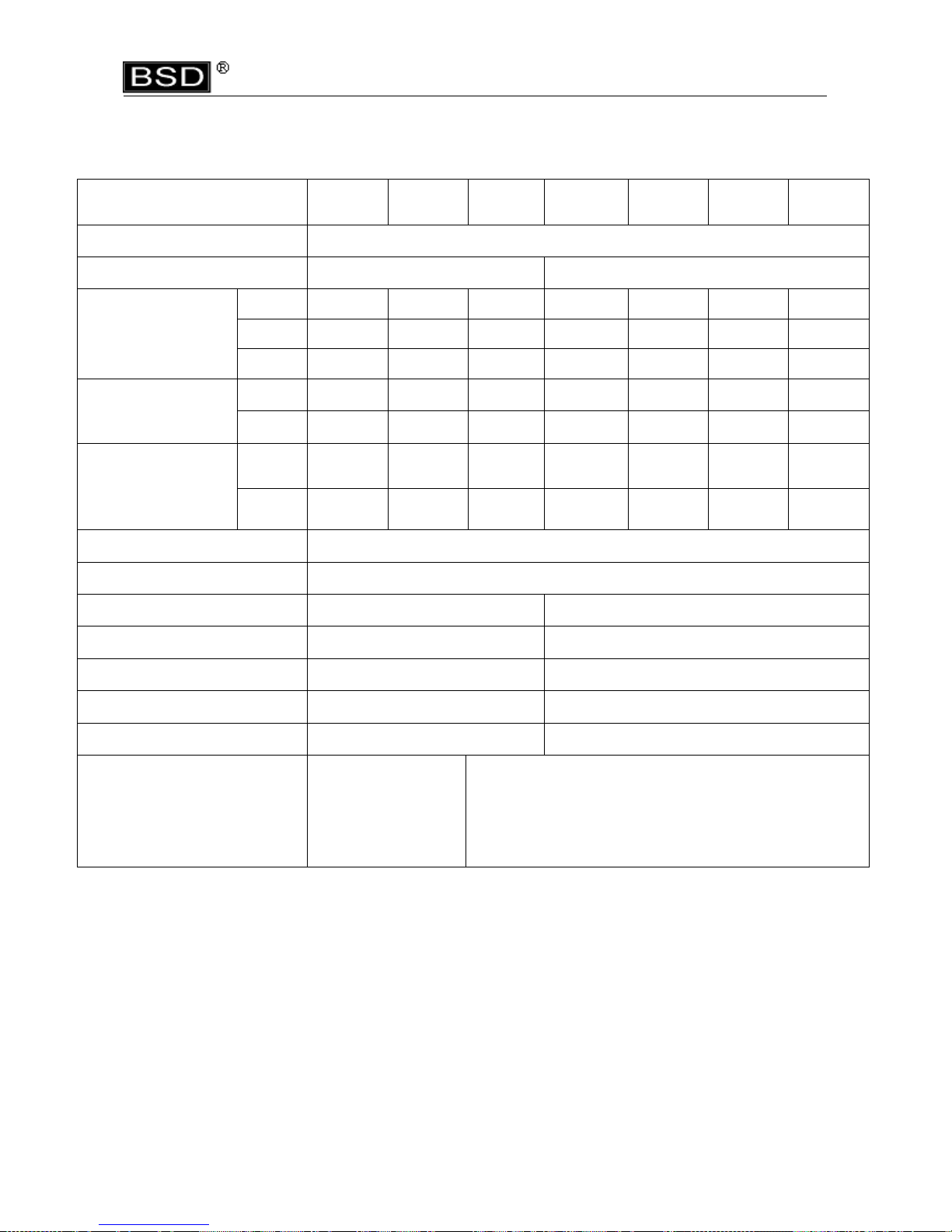
DATA2:
MODEL
BSD-
6200L
BSD-
6600L
BSD-
6600LF
BSD-
8000L
BSD-
8200L
BSD-
8800L
BSD-
8800LF
Input voltage(DC)
32VDC
Rated input
48W 50W
Bit torque
Kgf.cm
1 ~12 3~16 1~8 5~18 7~24 8~30 2~10
Lbf.in
0.89~10.44 2.57~13.89 0.89~6.9 4.33~15.84 6.11~20.8 6.9~26.02 1.77~8.67
N.m
0.1~1.18 0.29~1.57 0.1~0.78 0.49~1.76 0.69~2.35 0.78~2.94 0.2~0.98
Unloaded Rotation
Speed (R.p.m)
±10%
HI
1000 1000 2000 1000 750 530 2000
LO
700 700 X 700 520 350 ×
Metal assembly
screw(mm)
Machin
e screw
1.6~3.0 2.3~3.5 1.6~3.0 2.0~3.5 2.6~4.0 3.0~5.0 2.0~3.0
Tapping
screw
1.6~2.6 2.3~3.0 1.6~2.6 2.0~3.0 2.6~3.5 3.0~4.0 2.0~2.6
Torque Accuracy (%)
±3%
Torque Adjustment
Step less
Weight (g)
480 600
Length (mm)
230 260
Model of Torque Fixing Ring
KC-3 KC-2
Model of Suspension Rack
KH-3(KC&KH-3) KH-3(KC&KH-1)
Bit Type
HEX 5mm, HEX 6.35mm Ø4mm, Ø5mm
HEX 5mm ;HEX 6.35mm
Power controller
BSP-32HL-40W
BSP-32VR-40W
BSP-32HL-60W, BSP-32VR-60W
* 1N.m=10.2Kgf.cm 1N.m=8.85Lbf.in

BSD-3000 Series
Attaching / detaching bit and bit type
Push up the holder clamp by finger tip, and it will be unlocked. Thus, the bit can be freely
attached and detached (single finger notion type) select such a bit whose shank is equal
to the size shown below.
■Insert the power plug into a receptacle and set the changecover switch to “F” position.
■ Apply the bit to the screw head and press the lever or push main body to, then the
switch will be turned ON to start the motor running.
■ When the screw is tighten and reach the torque that you had set, The tool will stopped
automatically.
■ To reset the tool by releasing the lever to the original position or releasing the bit From
the screw head.
■ To return the screw, set the changeover switch to “R” position.
To adjust the torque on these screwdrivers. Proceed as follows :
1. Determine the torque output of the tool by checking a tightened Fastener with a torque
wrench.
2. Increase or decrease the torque by rotating the Spring Adjusting Ring. Rotating the
Ring clockwise to a higher number on the torque Scale increase torque output while
rotating the Ring counterclockwise to a lower number decreases the torque output.
3. Check the adjustment with a torque wrench. A number of factors will affect torque
output from one job to another. Final torque adjustment should be made at the job
through a of series of gradual increase. Always start below the desired torque and
work upward.
4. Adjust the bit torque by changing the driving in length of the adjust ring at the end.
5. The relationship between torque scale and bit torque is as shown Ring, in the torque
diagram. The figures of torque scale do not indicate bit torque values. However, the
clamping torque of screw itself is different form type, size, material of the screw and
the material of its mating part. Use it as standard to obtain an appropriate clamping
torque.
6. The (Return torque method) in which once-clamped screw is returned with torque
wrench or the like is available as one of torque control methods however, note that the
measured values by the return torque method generally appear in 10%~30% lower
than the actually clamping torque.
7. The torque checker measures the torque of screwdriver. The clamping torque of screw
itself is different from the clamped conditions. Understand the correlation between
clamping torque values and the torque checker values perform the torque control
properly.
4. Description of Operation
5. Torque Adjustment Operation

BSD-3000 Series
1. Also in reverse rotation, the clutch is turned off in such manner as in normal rotation,
stopping the motor running. Accordingly, when the screw tightened at a large torque,
set it to a higher torque scale.
2. The number from zero to eight on the Torque Scale are reference number only and not
an indication of actual torque output.
1. BIT Type : No. 00 ... Bit use in dia 1.3~1.8mm screw
No. 0.....Bit use in dia 1.6~2.0mm screw
No. 1.....Bit use in dia 2.0~2.6mm screw
No. 2.....Bit use in dia 3.0~4.0mm screw
BSD-3000L with BIT M3 Ø4×40 00# & 0# & 1# 1 Pce. Each
BSD-3200L with BIT M3 Ø4×40 00# & 0# & 1# 1 Pce. Each
BSD-3300L with BIT M3 Ø4×40 1# & 2# 1 Pce. Each
BSD-6200L with BIT 1# & 2# 1 Pce. Each
BSD-6600L with BIT 1# & 2# 1 Pce. Each
BSD-6600LF with BIT 1# & 2# 1 Pce. Each
BSD-8000L with BIT 1# &2 # 1 Pce. Each
BSD-8200L with BIT 1# & 2# 1 Pce. Each
BSD-8800L with BIT 2# 2 Pce.
BSD-8800LF with BIT 1# &2 # 1 Pce. Each
2.Carbon Brush :2 Pcs, Those 2 Pcs brush are spare parts.
3.Suspension rack and Torque fixing ring acceptable for use with the tool are available
from KILEWS catalogue.
6. Accessories
CAUTION

BSD-3000 Series
Maintenance and Inspection:
1. The screw driver must be operated in top condition, one day working hour must be not
more than eight hours.
2. Periodically check for wear of motor carbon brush, one day for eight hours use is
normal, replace it after every five to six months.
3. Please note don’t let the motor get over heated, every minute use 10~15 screws to
operate.
4. The frequency use of this electric screw driver is over than eight hours a day, still it
needs periodically testing and treatment. Every 5-6 months.
5. Inspect tool cords periodically and if damaged, have them repaired by an authorized
service facility. Inspect extension cords periodically and replace if damaged.
6. Do not remove any labels. Replace any damaged label.
1. The use of other than genuine KILEWS replacement parts may Result in decreased
tool performance and increased maintenance, and may invalidate all warranties.
2. All repairs and maintenance of this tool and its word must be performed by an
authorized service center.
3. KILEWS is not responsible for customer modification of tools for applications on which
KILEWS was not consulted.
4. Repairs should by made only by authorized, trained personnel. Consult your nearest
KILEWS authorized service center.
5. It is the responsibility of the employer to place the information in this manual into the
hands of the operator.
DO NOT ATTEMPT TO REPAIR THIS
ELECTRIC SCREW DRIVER
SAVE THESE INSTRUCTIONS
DO NOT DESTROY
7. Servicing
CAUTION
CAUTION


NO PARTS NO Q'ty NO PARTS NO Q'ty
1 AA50001N 1 GH28191-1 3
2 PZ50160 1 32 GG28211 1
3 CJ20011 1 G21507 1
4 CC28021 1 33 M11308 1
CC28021-2 1 G20103 1
5 CB28001-1 1 34 GH28191 3
CB28001-4 1 GH28191-1 3
6 CA28151-1 1 35 GG28211 1
CA28151-4 1 GG28211-1 1
7 HB50061 1 36 GN28221 1
8 CE28051-1 1 37 GA28231-3 1
9 CE28061 1 38 GC28241-2 1
10 H10201 1 GC28241-1 1
11 HA28071-4 1 GC28241 1
12 CI60216 1 39 GN28251 1
CI60211 1 40 GP30371 2
CI60212 1 41 GU28261-1 1
13 CH20102 3 42 GP21291A 2
14 MO28081-0 1 43 GD28281C-1 1
MO28081-2 1 GD28281B 1
MO28081-1 1 44 G21203 2
15 MI30511-2 1 45 GT28282B 2
16 EB33610-2 1 46 GP20331 1
17 MD20151 2 GP21291B 2
18 MC50161-1 2 47 GF28291 1
19 ML28131F 1 48 GE28321 1
20 ME28121 2 GE28321-3 1
21 MH28161-1 1 GE28321-4 1
MH28161-2 1 49 GO28241 1
MH28161-7 1 50 GO28251 1
22 MJ28171-1 1 51 GY28331 1
MJ28171-2 1 52 GN28341 1
23 MB28141 1 53 GB21332
2
24 MA33621B 2 54 GO28361 1
25 MK28091 1 GO28361-1 1
MK28091-1 1 55 GJ28371 1
26 MG30081 1 GJ3046B 1
27 GZ28111-1C 1 56 GQ28411 1
GZ28111-1B 1 GQ21361 1
GZ28111-2C 1 57 GL28381 4
GZ28111-2B 1 58 GM28391 1
GZ28111-3C 1 59 CD28041 1
GZ28111-3B 1 CD28041-1 1
28 MI28101-1 1
60 CH30672C 1
29 GK28181-1 1
61 CH20102-18 1
30 GI28441 1
62 CH30192 1
31 GH28191 3
63
CK28031 1
64 G21436-1 1
GEAR SEAT FOR "3300L"
GEAR SEAT"3000L&3200L"
PARTS NAME-E
IDLE GEAR FOR "3300L"
IDLE GEAR FOR "3000L&3200L"
CENTRAL GEAR FOR "3300L"
CENTRAL GEAR FOR "3000L&3200L"
IDLE GEAR FOR "3300L"
GEAR CASE
MAIN BEARING
GEAR SEAT FOR "3300L"
GEAR SEAT FOR "3000L&3200L"
BALL BEARING
CAM FOR "3200L"
CAM FOR "3300L"
CAM FOR"3000L"
SHAFT FOR "3000LC/3200LC/3300LC" TYPE
STELL BALLS for 3mm
STOP PILOT
STEEL BALLS "3.15mm"
BIT PILOT FOR "C"TYPE 2mm
BIT HOLDER(B:6.35)
PINS FOR GT28282B
SHAFT FOR "B" TYPE
WARING SPRING FOR "3200L"
WARING SPRING FOR "3000L"
WARING PLATE TYPE
BIT PILOT FOR "B"TYPE 2.5mm
WARING SPRING SEAT
TRIANGLE SPRING "3000L&3200L"
SPRING CUP FOR "3000L&3200L"
WARING SPRING FOR "3300L"
TRIGGER SPRING
BIT SPRING FOR "B"TYPE
BIT SPRING FOR "C"TYPE
CLUTCH CASE
BALL BEARING
C-RING FOR "B"TYPE
C-RING FOR "C"TYPE
BIT SLEEVE FOR "B"TYPE
BIT SLEEVE FOR "C"TYPE
COUPLER (ESD)
COUPLER
TORQUE ADJUSTING RING
TORQUE ADJUSTING PINS
SCREW
WASHER
GROUNDING MEANS
PILOT ROD
"C" RING
IRON WASHER
CLUTCH ASSEMBLY FOR "3000LB"
CLUTCH ASSEMBLY FOR "3200LC"
CLUTCH ASSEMBLY FOR "3200LB"
CLUTCH ASSEMBLY FOR "3300LC"
CLUTCH ASSEMBLY FOR "3300LB"
FAN FOR 3000L& 3200L
FAN FOR 3300L
PILOT ROD
CLUTCH ASSEMBLY FOR "3000LC"
MOTOR YOKE ASSEMBLY FOR "3000L"
MOTOR YOKE ASSEMBLY "3200L&3300L"
MOTOR END COVER
ASSEMBLING SPRING
BALL BEARING
ARMATURE FOR "3000L"
ARMATURE FOR "3200L"
ARMATURE FOR "3300L"
CERAMICS CAPACITOR
BRUSH CAP
CAPBON BRUSH
MOTOR TOP COVER
START SWITCH
PILOT ROD
CHANGEOVER SWITCH CAP FOR "3000L"
CHANGEOVER SWITCH CAP FOR "3200L"
CHANGEOVER SWITCH CAP FOR "3300L"
SCREW
MOTOR ASSEMBLY FOR "3300L"
BSD-3000L 3200L 3300L
PARTS NAME-E
CORD ASSEMBLY 2M
CONNECTOR ASS'Y
PUSH ROD
FIXTURE
HOUSING-UNDERSIDE (ESD)
HOUSING-UPSIDE
HOUSING-UPSIDE (ESD)
WASHER FOR "C"TYPE
IDLE GEAR FOR "3000L&3200L"
SUSPENSION RING
TRIGGER ASSEMBLY
TRIGGER ASSEMBLY (ESD)
HOUSING-UNDERSIDE
SHUT OFF SWITCH
CHANGEOVER SWITCH
MOTOR ASSEMBLY FOR "3000L"
MOTOR ASSEMBLY FOR "3200L"


NO PARTS NO PARTS NAME-E Q'ty NO PARTS NO PARTS NAME-E Q'ty
1 AA50001
N
CORD ASSEMBLY 2
M
1 32 GH20241 IDLE GEA
R
8
AA50001-1
N
CORD ASSEMBLY 3
M
1 33 GG20271 GEAR SEA
T
2
2 PZ5016
0
CONNECTO
R
1 34 G20101 CENTRAL GEA
R
1
3 CJ20011 SUSPENSION RIN
G
1 35 GA30311-
7
GEAR CAS
E
1
4
CC50011 TRIGGER ASSEMBLY 1
36 GN30321 MAIN BEARIN
G
1
CC50011-
2
TRIGGER ASSEMBLY (ESD
)
1 37 GC30341 CAM 1
5
CB50031-1 HOUSUNG-UNDERSIDE 1
38 GP30351 STEEL BALLS 2
CB50031-4 HOUSUNG-UNDERSIDE
(
ESD
)
1
39 GU30361 STOP PILO
T
1
6
CA50221-1 HOUSUNG-UPSIDE 1
40 GP30371 STELL BALLS 3.15mm
(A,C,D,AD)
2
CA50221-4 HOUSUNG-UPSIDE
(
ESD
)
1
GP30351 STELL BALLS 4mm
(B)
2
7 HB50073 START SWITC
H
1 41 GD30381
A
SHAFT FOR "A" TYP
E
1
8 CH30003 SCREW 1 GD30381B SHAFT FOR "B" TYP
E
1
9 CE50121-1 PUSH ROD 1 GD30381
C
SHAFT FOR "C" TYP
E
1
10 CE50151 FIXTUR
E
1 GD30381
D
SHAFT FOR "D" TYP
E
1
11 H10201 SHUT OFF SWITC
H
1 GD30383A
D
SHAFT FOR "AD" TYP
E
1
12 HA50091
F
CHANGEOVER SWITC
H
1 42 GP20331 STEEL BALLS FOR "A,D,AD" TYPE(2mm
)
2
13
CI50211 CHANGEOVER SWITCH CAP FOR"6200L
"
1
GP21291B STEEL BALLS FOR "B
,
C" TYPE(2.5mm
)
2
CI50211-1 CHANGEOVER SWITCH CAP FOR"6600L
"
1
43 GF30401 WARING PLATE FOR "A
,C,D,
AD" TYP
E
1
14 CH90151-1 SCREW 2 GF30401B WARING PLATE FOR "B" TYP
E
1
15 CH2010
2
SCREW 3 44 GO30541-3 SPRING FOR "6200L" 1
16 MO50111 MOTOR ASSEMBLY "6200L
"
1 GO30541-1 SPRING FOR "6600L" 1
MO50111-1 MOTOR ASSEMBLY "6600L
"
1 45 GO30531 SPRING CA
P
1
17 MI30511-3 PILOT RO
D
1 46 GE50411-1 WARING SPRING FOR "6200LA,C,D,AD
"
1
18 MD20151 BRUSH CA
P
2 GE50411-
2
WARING SPRING FOR "6200LB
"
1
19 MC71411-1 CAPBON BRUS
H
2 GE30413-
2
WARING SPRING FOR "6600LA,C,D,AD
"
1
20 ML50571
F
MOTOR TOP COVE
R
1 GE30411-1
0
WARING SPRING FOR "6600LB
"
1
21 ME20181 BALL BEARIN
G
2 47 GY30421 WARING SPRING BASE FOR "A,C,D,AD" TYP
E
1
22 MH50601 ARMATURE FOR "6200L
"
1 GY30421B WARING SPRING BASE FOR "B" TYP
E
1
MH50601-1 ARMATURE FOR "6600L
"
1 48 GK20231B "C"-RING FOR GY30421B (LB
)
1
23 MJ50631 MOTOR YOKE ASSEMBLY "6200L
"
1 49 GB30441-12
A
CLUTCH CASE (A,C,D,AD
)
1
MJ30631 MOTOR YOKE ASSEMBLY "6600L
"
1 GB30441-1
A
CLUTCH CASE (B
)
1
24 MB20221 MOTOR END COVE
R
1 50 GO20391 BIT SPRING FOR "A,C,D,AD" TYP
E
1
25 MA20211B ASSEMBLING SPRIN
G
2 GO20391B BIT SPRING FOR "B" TYP
E
1
26 MK20131-1 FAN 1 51 GJ30461 BIT SLEEVE FOR "A
,C,D,
AD" TYP
E
1
27 MG30081 PILOT RO
D
1 GJ3046B BIT SLEEVE FOR "B" TYP
E
1
28 GZ30071-2
A
CLUTCH ASSEMBLY FOR "6200LA
"
152GQ30471 "C" RING (A,C,D,AD
)
1
GZ30071-2B CLUTCH ASSEMBLY FOR "6200LB
"
1G
Q
21361 "C" RING (B
)
1
GZ30071-2
C
CLUTCH ASSEMBLY FOR "6200LC
"
1 53 GL30481-1 TORQUE ADJUST PI
N
4
GZ30071-2
D
CLUTCH ASSEMBLY FOR "6200LD
"
1 54 GM30491 TORQUE ADJUST RIN
G
1
GZ30071-2A
D
CLUTCH ASSEMBLY FOR "6200LAD
"
1 55 GS30501 "C" RING FOR GM30491 1
GZ30071-3
A
CLUTCH ASSEMBLY FOR "6600LA
"
1
56
CD20111 COUPLE
R
1
GZ30071-3B CLUTCH ASSEMBLY FOR "6600LB
"
1 CD20111-3 COUPLER ES
D
1
GZ30071-3C CLUTCH ASSEMBLY FOR "6600LC" 1 57
CH50671-4
GROUNDING MEANS 1
GZ30071-3
D
CLUTCH ASSEMBLY FOR "6600LD
"
1 58 CH20102-1
8
WASHE
R
1
GZ30071-3A
D
CLUTCH ASSEMBLY FOR "6600LAD
"
1 59 CH3019
2
SCREW 1
29 MI30241 PILOT ROD FOR"A
,C,D,
AD"TYP
E
1 60 EB33610-
2
CERAMICS CAPACITO
R
1
MI30241-1 PILOT ROD FOR"B"TYP
E
161
CK28031-1 TRIGGER SPRIN
G
1
30 GK20231 "C" RING 1 62 GN30435 MAIN BEARIN
G
1
31 GI20251-1 IRON WASHE
R
1
6200L 6600L


NO PARTS NO PARTS NAME-E Q'ty NO PARTS NO PARTS NAME-E Q'ty
1 AA50001N CORD ASSEMBLY 2M 1 35 GA30311-7 GEAR CASE 1
AA50001-1N CORD ASSEMBLY 3M 1 36 GN30321 MAIN BEARING 1
2 PZ50160 CONNECTOR 1 37 GC30341 CAM 1
3 CJ20011 SUSPENSION RING 1 38 GP30351 STEEL BALLS 2
4
CC50011 TRIGGER ASSEMBLY 1
39 GU30361 STOP PILOT 1
CC50011-2 TRIGGER ASSEMBLY (ESD) 1 40 GP30371 STELL BALLS 3.15mm (A,C,D,AD) 2
5
CB50031-1 HOUSUNG-UNDERSIDE 1
GP30351 STELL BALLS 4mm (B) 2
CB50031-4 HOUSUNG-UNDERSIDE (ESD) 1
41 GD30381A SHAFT FOR "A" TYPE 1
6
CA50221-1 HOUSUNG-UPSIDE 1
GD30381B SHAFT FOR "B" TYPE 1
CA50221-4 HOUSUNG-UPSIDE (ESD) 1
GD30381C SHAFT FOR "C" TYPE 1
7 HB50073 START SWITCH 1 GD30381D SHAFT FOR "D" TYPE 1
8 CH30003 SCREW 1 GD30383AD SHAFT FOR "AD" TYPE 1
9 CE50121-1 PUSH ROD 1 42 GP20331 STEEL BALLS FOR "A,D,AD" TYPE(2mm) 2
10 CE50151 FIXTURE 1 GP21291B STEEL BALLS FOR "B,C" TYPE(2.5mm) 2
11 H10201 SHUT OFF SWITCH 1 43 GF30401 WARING PLATE FOR "A,C,D,AD" TYPE 1
12 HA50091F CHANGEOVER SWITCH 1 GF30401B WARING PLATE FOR "B" TYPE 1
13
CI50211-1 CHANGEOVER SWITCH CAP FOR"6600LF" 1
44 GO30541 SPRING 1
14 CH90151-1 SCREW 2 45 GO30531 SPRING CAP 1
15 CH20102 SCREW 3 46 GE30411-9 WARING SPRING FOR "6600LFA,C,D,AD" 1
16 MO50111-2 MOTOR ASSEMBLY 1 GE30411-14 WARING SPRING FOR "6600LFB" 1
17 MI30511-3 PILOT ROD 1 47 GY30421 WARING SPRING BASE FOR "A,C,D,AD " TYPE 1
18 MD20151 BRUSH CAP 2 GY30421B WARING SPRING BASE FOR "B" TYPE 1
19 MC50161-1 CAPBON BRUSH 2 48 GK20231B "C"-RING FOR GY30421B (LB) 1
20 ML50571-3F MOTOR TOP COVER 1 49 GB30441-12A CLUTCH CASE (A,C,D,AD) 1
21 ME21481 BALL BEARING 2 GB30441-1A CLUTCH CASE (B) 1
22 MH50601-5 ARMATURE 1 50 GO20391 BIT SPRING FOR "A,C,D,AD" TYPE 1
23 MJ33631F MOTOR YOKE ASSEMBLY 1 GO20391B BIT SPRING FOR "B" TYPE 1
24 MB20221-1 MOTOR END COVER 1 51 GJ30461 BIT SLEEVE FOR "A,C,D,AD" TYPE 1
25 MA33621B ASSEMBLING SPRING 2 GJ3046B BIT SLEEVE FOR "B" TYPE 1
26 MK33091LF FAN 1 52 GQ30471 "C" RING (A,C,D,AD) 1
27 MG30081-1 PILOT ROD 1 GQ21361 "C" RING (B) 1
28
GZ50071-3AF CLUTCH ASSEMBLY FOR 6600LFA 1
53 GL30481-1 TORQUE ADJUST PIN 4
GZ50071-3BF CLUTCH ASSEMBLY FOR 6600LFB 1
54 GM30491 TORQUE ADJUST RING 1
GZ50071-3CF CLUTCH ASSEMBLY FOR 6600LFC 1
55 GS30501 "C" RING FOR GM30491 1
GZ50071-3DF CLUTCH ASSEMBLY FOR 6600LFD 1
56 CD20111 COUPLER 1
GZ50073-4ADF
CLUTCH ASSEMBLY FOR 6600LFAD 1
CD20111-3 COUPLER(ESD) 1
29 MI30241 PILOT ROD FOR"A,C,D,AD"TYPE 1 57
CH50671-4
GROUNDING MEANS 1
MI30241-1 PILOT ROD FOR"B"TYPE 1 58 CH20102-18 WASHER 1
30 GK20231 "C" RING 1 59 CH30192 SCREW 1
31 GI20251-1 IRON WASHER 1 60 EB33610-2 CERAMICS CAPACITOR 1
32 G21302 SPACER 1 61 CK28031-1 TRIGGER SPRING 1
33 GH20241-1 IDLE GEAR 3 62 GN30435 MAIN BEARING 1
34 GG20271-1 GEAR SEAT 1
6600LF


NO PARTS NO PARTS NAME-E Q'ty NO PARTS NO PARTS NAME-E Q'ty
1 AA50001N CORD ASSEMBLY 2M 1 30 MI31221 PILOT ROD 1
2 PZ50160 CONNECTOR 1 31 GK21181 "C"RING 1
3 CJ20011 SUSPENSION RING 1 32 GI21191 IRON WASHER 1
4 CC21011-3
TRIGGER ASSEMBLY
1 33 GH20241 IDLE GEAR FOR "8000L" 6
CC21011-6 TRIGGER ASSEMBLY -ESD 1 GH91232 IDLE GEAR FOR "8200L" 6
5 CB71031-1 HOUSUNG-UNDERSIDE 1
GH92231 IDLE GEAR FOR "8800L" 8
CB71031-3 HOUSUNG-UNDERSIDE (ESD) 1
34 GG21231 GEAR SEAT FOR "8000L" 1
6 CA71201-1 HOUSUNG-UPSIDE 1
GG91242 GEAR SEAT FOR "8200L" 1
CA71201-3 HOUSUNG-UPSIDE (ESD) 1
GG92241 GEAR SEAT FOR "8800L" 1
7 HB91061 SHUT OFF SWITCH 1 35 G20102 CENTRAL GEAR FOR "8000L" 1
8 CE90101-1 SWITCH BASE 1 36 GG21231 GEAR SEAT FOR "8000L" 1
9 HB50061 START SWITCH 1 GG91272 GEAR SEAT FOR "8200L" 1
10 CH90121 SCREW 1 GG92271 GEAR SEAT FOR "8800L" 1
11 CH90131 SCREW 1 37 GA21241 GEAR CASE FOR "8000L" 1
12 CH90151-1 SCREW 2 GA35241 GEAR CASE FOR "8200L&8800L" 1
13 HA28071-4 CHANGEOVER SWITCH 1 38 GN21251 MAIN BEARING 1
14 CI60213 CHANGEOVER SWITCH CAP-8000L 1 39 GW21531 IRON RING 1
CI60214 CHANGEOVER SWITCH CAP-8200L 1 40 GC31321 CAM 1
CI60212 CHANGEOVER SWITCH CAP-8800L 1 41 GP30351 STELL BALLS(4mm) 4
15 CH20102 SCREW 3 42 GU30361 STOP PILOT-LA 1
16 MO71051 MOTOR ASSEMBLY FOR 8000L 1 GU30371 STOP PILOT-LB 1
MO71051-3 MOTOR ASSEMBLY FOR 8200L 1 43 GD31351A SHAFT FOR "A"TYPE 1
MO71051-4 MOTOR ASSEMBLY FOR 8800L 1 GD31353B SHAFT FOR "B"TYPE 1
17 MI31611 PILOT ROD 1 GD31351AD SHAFT FOR "AD"TYPE 1
18 EB33610-2 CERAMICS CAPACITOR 1 44 GP21291A BIT PILOT FOR HEX 5.0mm 2
19 MD20151 BRUSH CAP 2 GP21291B BIT PILOT FOR HEX 6.35mm 2
20 MC71411 CARBON BRUSH 2 45 GF31371 WARING PLATE-HEX 5.0mm 1
21 ML70531F MOTOR TOP COVER 1 GF31372 WARING PLATE-HEX 6.35mm 1
22 ME21481 BALL BEARING 2 46 GE90361-7 WARING SPRING FOR "8000L" 1
23 MH70571-1 ARMATURE 1 GE90361-7B WARING SPRING FOR "8200L" 1
24 MJ90601 MOTOR YOKE ASSEMBLY 1 GE90361-7E WARING SPRING FOR "8800L"1
25 MB21521A MOTOR END COVER 1 47 GY21321 WARING SPRING BASE-LB 1
26 MA21491B ASSEMBLING SPRING 2 GY31391 WARING SPRING BASE-LA 1
27 MK21111 FAN FOR "8000L" 1 48 GK20231B "C"RING 1
MK91091 FAN FOR "8200L" 1 49 GB21331 CLUTCH CASE 1
MK92091 FAN FOR "8800L" 1 50 GO21341 BIT SPRING 1
28 MG91081 PILOT ROD 1 51 GJ21351 BIT SLEEVE 1
29 GZ71091A CLUTCH ASSEMBLY FOR "8000A" 1 52 GQ21361 "C"RING 1
GZ71091B CLUTCH ASSEMBLY FOR "8000B" 1 53 GL21371 TORQUE ADJUSTING PINS 4
GZ71091AD CLUTCH ASSEMBLY FOR "8000AD" 1 54 GM21381 TORQUE ADJUSTING RING 1
GZ71091-2A CLUTCH ASSEMBLY FOR "8200A" 1 55 GS21391 "C"RING 1
GZ71091-2B CLUTCH ASSEMBLY FOR "8200B" 1 56
CD21031 COUPLER 1
GZ71091-2AD CLUTCH ASSEMBLY FOR "8200AD" 1
CD21031-1 COUPLER-ESD 1
GZ71091-8A CLUTCH ASSEMBLY FOR "8800A" 1 57 CH30671-1 GROUNDING MEANS1
GZ71091-8B CLUTCH ASSEMBLY FOR "8800B" 1 58 CK28031-1 TRIGGER SPRING 1
GZ71091-3AD CLUTCH ASSEMBLY FOR "8800AD" 1 59 GN30442 MAIN BEARING 1
8000L 8200L 8800L
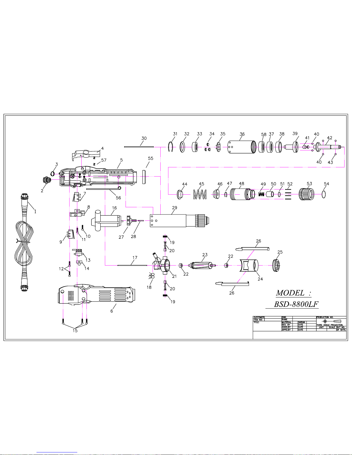

NO PARTS NO PARTS NAME-E Q'ty NO PARTS NO PARTS NAME-E Q'ty
1 AA50001N CORD ASSEMBLY 2M 1 31 GK21181 "C"RING 1
2 PZ50160 CONNECTOR 1 32 GI21191 IRON WASHER 1
3 CJ20011 SUSPENSION RING 1 33 G21301 SPACER 1
4 CC21011-3
TRIGGER ASSEMBLY
1 34 GH21221-1 IDLE GEAR 3
CC21011-6 TRIGGER ASSEMBLY -ESD 1 35 GG21231-1 GEAR SEAT 1
5 CB71031-1 HOUSUNG-UNDERSIDE 1
36 GA21241 GEAR CASE 1
CB71031-3 HOUSUNG-UNDERSIDE (ESD) 1
37 GN21251 MAIN BEARING 1
6 CA71201-1 HOUSUNG-UPSIDE 1
38 GW21531 IRON RING 1
CA71201-3 HOUSUNG-UPSIDE (ESD) 1
39 GC31321 CAM 1
7 HB91061 SHUT OFF SWITCH 1 40 GP30351 STELL BALLS(4mm) 4
8 CE90101-1 SWITCH BASE 1 41 GU30361 STOP PILOT-LA 1
9 HB50061 START SWITCH 1 GU30371 STOP PILOT-LB 1
10 CH90121 SCREW 1 42 GD31351A SHAFT FOR "A"TYPE 1
11 CH90131 SCREW 1 GD31353B SHAFT FOR "B"TYPE 1
12 CH90151-1 SCREW 2 GD31351AD SHAFT FOR "AD"TYPE 1
13 HA28071-4 CHANGEOVER SWITCH 1 43 GP21291A BIT PILOT FOR HEX 5.0mm 2
14 CI60212 CHANGEOVER SWITCH CAP-8800LF 1 GP21291B BIT PILOT FOR HEX 6.35mm 2
15 CH20102 SCREW 3 44 GF31371
WARING PLATE FOR HEX 5.0mm
1
16 MO71051-5 MOTOR ASSEMBLY 1 GF31372 WARING PLATE FOR HEX 6.35mm 1
17 MI31611 PILOT ROD 1 45 GE90361-7M WARING SPRING 1
18 EB33610-2 CERAMICS CAPACITOR 1 46 GY21321 WARING SPRING BASE-LB 1
19 MD20151 BRUSH CAP 2 GY31391 WARING SPRING BASE-LA 1
20 MC71411 CARBON BRUSH 2 47 GK20231B "C"RING 1
21 ML70531F MOTOR TOP COVER 1 48 GB21331 CLUTCH CASE 1
22 ME21481 BALL BEARING 2 49 GO21341 BIT SPRING 1
23 MH70571-1 ARMATURE 1 50 GJ21351 BIT SLEEVE 1
24 MJ90601 MOTOR YOKE ASSEMBLY 1 51 GQ21361 "C"RING 1
25 MB21521A MOTOR END COVER 1 52 GL21371 TORQUE ADJUSTING PINS 4
26 MA21491B ASSEMBLING SPRING 2 53 GM21381 TORQUE ADJUSTING RING 1
27 MK21111PF FAN 1 54 GS21391 "C"RING 1
28 MG30081-1 PILOT ROD 1 55
CD21031 COUPLER 1
29 GZ71091-8AF CLUTCH ASSEMBLY FOR "8800LAF" 1
CD21031-1 COUPLER-ESD 1
GZ71091-8BF CLUTCH ASSEMBLY FOR "8800LBF" 1 56 CH30671-1 GROUNDING MEANS 1
GZ71091-8ADF CLUTCH ASSEMBLY FOR "8800LADF" 1 57
CK28031-1 TRIGGER SPRING 1
30 MI31221 PILOT ROD 1 58 GN30442 MAIN BEARING 1
8800LF

NO PARTS NO PARTS NAME-E Q'ty
1
AA60005
CORD NS-26 1.5M-Chinese
1
AA60005-D
CORD NS-26 1.5M-Australia 1
AA60005-A
CORD NS-26 1.5M-American 1
AA60005-E
CORD NS-26 1.5M-Europe 1
AA60005-I
CORD NS-26 1.5M-India 1
AA60005-U
CORD NS-26 1.5M-UK 1
2
P11011-3
HOUSING 32V 60W HI/LO 1
P11012-3
HOUSING 32V 40W HI/LO 1
P11011-4 HOUSING 32V 60W VR 1
P11012-4 HOUSING 32V 40W VR 1
3 EG50101-22 PCB-POWER SUPPILY FOR 40W HI/LO 1
EG50101-22I-CE PCB-POWER SUPPILY FOR 60W HI/LO 1
EG50101-22E PCB-POWER SUPPILY FOR 40W VR 1
EG50101-22F-CE PCB-POWER SUPPILY FOR 60W VR 1
4 P11401-7
POWER SWITCH BR-12C-11L
1
5 EG50101-3G-A PCB 1

KILEWS ELECTRIC TOOLS(SHANGHAI)CO., LTD.
E-mail:service@kilews.com.cn
http://www.kilews.com.cn
 Loading...