

Kikusui TOS93 series, TOS9320 User Manual
TOS9320
User’s Manual
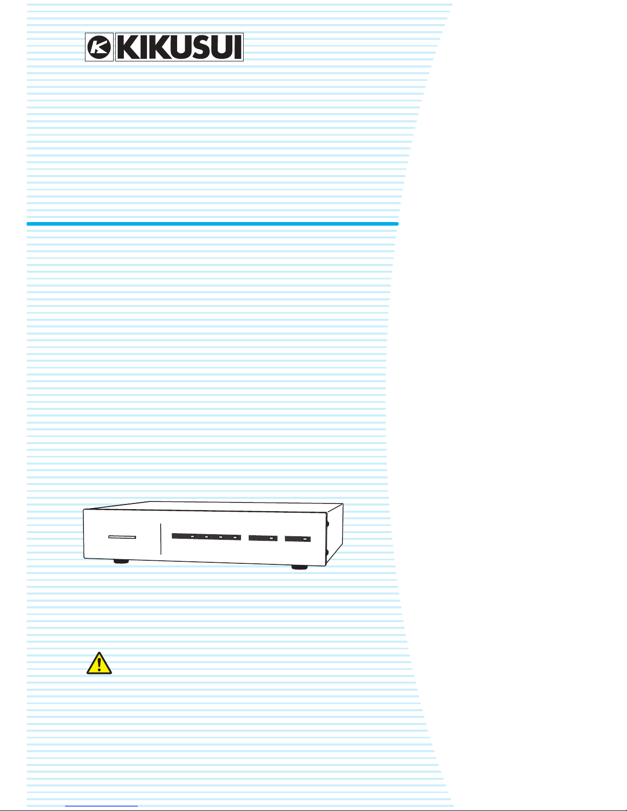
High voltage scanner
TOS93 series
DANGER
This product generates high voltage!
Improper operation can lead to serious accidents.
To prevent accidents, be sure to read the section
“Safety Precautions for Testing” in this manual.
Keep this manual close to the product so that the operators
can read the manual at any time.
Contents 6
Component Names 7
Safety Precautions for Testing 9
Installation 13
External Control 25
Maintenance 29
Specifications 30
Appendix 34
Part No. IB032321
Nov 2018
2 User’s Manual TOS9320
Notes to the Supervisor
• If the operators cannot understand the language used in this manual, translate the manuals
into the appropriate language.
• Make sure that the operators understand the information in this manual before they operate
this product.
• Keep this manual close to the product so that the operators can read the manual at any time.
You will receive a potentially fatal electric shock if:
• You touch an output terminal while output is being generated.
• You touch a test lead that is connected to an output terminal while output is being generated.
• You touch the EUT while output is being generated.
• You touch a location that is electrically connected to an output terminal while output is being
generated.
• You touch a location that is electrically connected to an output terminal immediately after output is turned off after a DC withstanding voltage test or insulation resistance test has been
performed.
DANGER
TOS9320 User’s Manual 3
This manual provides an overview of the product and notes on
usage. It also explains how to configure it, operate it, perform
maintenance on it, and so on. Read this manual thoroughly
before use, and use the product properly.
Intended readers
These manuals are intended for users of this product and their
instructors. The manuals assume that the reader has knowledge about electric safety testing.
Manual construction
• User's manual (this manual)
This document is intended for first-time users of this product. It provides an overview of the product, notes on usage,
and specifications. It also explains how to connect the product, operate the product, perform maintenance on the product, and so on.
• Safety information
This document contains general safety precautions. Keep
them in mind and make sure to observe them.
Trademarks
All company names and product names used in this manual
are trademarks or registered trademarks of their respective
companies.
Copyright
Reproduction and reprinting of this operation manual, whole or
partially, without our permission is prohibited.
Both unit specifications and manual contents are subject to
change without notice.
Copyright© 2018 Kikusui Electronics Corporation
Affix the high-voltage warning stickers in locations that are
easily visible on the product or around the installation location.
About Manuals
PaperPaper
PaperPaper
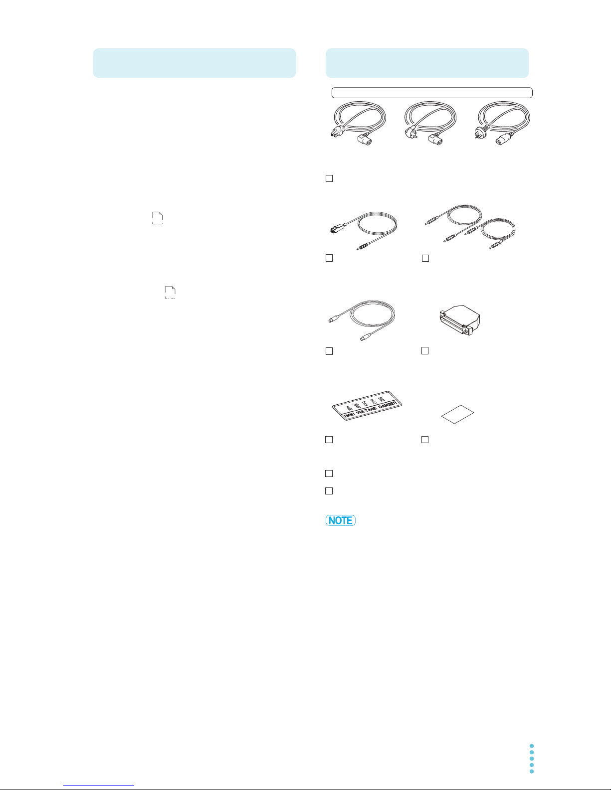
Accessories
High-voltage test lead
[TL31-TOS] (8 red)
Lead for high voltage parallel
connection
TL33-TOS (1 pair)
Power cord (1 pc., length: 2.5 m)
User’s manual (1 copy)
Safety Information (1 copy)
Plug: CEE7/7
Rating: 250 Vac/10 A
[85-10-1070]
Plug: GB1002
Rating: 250 Vac/10 A
[85-10-0791]
or or
The attached power cord varies depending on the shipment destination.
Interface cable (1 pc.)
High-voltage warning
sticker (2 pc.)
Channel labels
For the panel (1 sheet)
For the test leads (1 sheet)
CONTROLLER INTERFACE
plug (1 set)
Assembly type
[D-sub plug unit]
Plug: NEMA5-15
Rating: 125 Vac/10 A
[85-AA-0003]

4 User’s Manual TOS9320
The TOS9320 High Voltage Scanner is an option for the
TOS93 Series Multifunction Safety Tester. It is equipped with a
function for distributing the test voltage supplied from the tester to multiple test points in withstanding voltage tests and
insulation resistance tests.
The CONTROLLER INTERFACE connector on the rear panel
can be used to control channels from an external device.
When combined with an external controller, output from Kikusui TOS5300 series withstanding voltage and insulation resistance tester and the like can also be distributed.
The TOS9320 scanner adds the following functions to the tester.
• A single TOS9320 scanner expands an output to four channels. Each channel can be set to an electric potential of your
choice (high, low, or open), and withstanding voltage tests
or insulation resistance tests can be performed on any of
the four test points.
• Up to four TOS9320 scanners can be connected to a single
TOS93. When four scanners are connected, the output can
be expanded up to 16 channels.
• The output of each channel and the contact between each
test point can be verified.
These functions save power when testing electric/electronic
devices and components that have multiple test points and
enable highly reliable withstanding voltage and insulation
resistance tests.
• The TOS9320 High Voltage Scanner is also referred to as
the TOS9320 scanner.
• The TOS9300, TOS9301, TOS9302, TOS9303, and
TOS9303LC multifunction safety testers are also referred to
as the TOS93 series or TOS93 series testers.
• A tester connected to this product is also simply referred to
as the tester.
• The term “PC” is used to refer generally to both personal
computers and workstations.
• The term “EUT” is used to refer generally to an equipment
under test.
• The following markings are used in this manual.
Indicates an imminently hazardous situation which,
if ignored, will result in death or serious injury.
Indicates a potentially hazardous situation which, if
ignored, could result in death or serious injury.
Indicates a potentially hazardous situation which, if
ignored, may result in slight injury or damage to the
product or other property.
Indicates information that you should know.
Product Overview
Notations Used in This Manual
TOS9320 User’s Manual 5
When using this product, be sure to observe the precautions in
the Safety Information manual. Items specific to this product
are given below.
• You will receive a potentially fatal electric shock if:
• You touch an output terminal while output is being generated.
• You touch a test lead that is connected to an output terminal while output is being generated.
• You touch the EUT while output is being generated.
• You touch a location that is electrically connected to an
output terminal while output is being generated.
• You touch a location that is electrically connected to an
output terminal immediately after output is turned off after
a DC withstanding voltage test or insulation resistance
test has been performed.
• You may receive a potentially fatal electric shock if:
• You operate the tester without grounding it.
• You operate the tester without using rubber gloves for
electrical work.
• You come close to a location that is electrically connected
to an output terminal while output is being generated.
• You come close a location that is electrically connected to
an output terminal immediately after output is turned off
after a DC withstanding voltage test or insulation resistance test has been performed.
• Do not touch the tip of the test lead with your hand.
Risk of electric shock.
• Do not use this product near highly sensitive measuring instruments or receivers.
Noise generated by this product may affect other devices.
At a test voltage of 3 kV or greater, the product may produce corona discharge between its test lead clips. This will
generate a significant amount of broadband RF emission.
To minimize this effect, keep the alligator clips away from
each other. Also, keep the alligator clips and test leads
away from conducting surfaces, especially sharp metal
edges.
• Do not exceed the stacking limit.
Stack only a single TOS9320 scanner on top of a TOS93
series tester. Otherwise, it may cause injury to the operator
or damage to the product when it falls down.
If you are using multiple TOS9320 scanners, rack mount
them, or install them next to the tester. When stacking scanners, do not stack more than two scanners.
• When installing this product, be sure to observe the temperature and humidity ranges indicated below.
Operating temperature range: 0 °C to 40 °C (32 °F to
104 °F)
Operating humidity range: 20 %rh to 80 %rh (no condensation)
• When storing this product, be sure to observe the temperature and humidity ranges indicated below.
Storage temperature range: -20 °C to 70 °C (-4 °F to
158 °F)
Storage humidity range: 90 %rh or less (no condensation)
Safety Precautions
Notes on Usage

6 User’s Manual TOS9320
Contents
About Manuals...................................................3
Accessories ....................................................... 3
Product Overview .............................................. 4
Notations Used in This Manual.......................... 4
Safety Precautions ............................................ 5
Notes on Usage................................................. 5
Component Names............................................ 7
Safety Precautions for Testing
Lighting of the DANGER LED............................ 9
Test Precautions................................................9
Pre-test precautions .......................................... 9
Testing precautions......................................... 10
Precautions when changing test conditions ........ 10
Precautions after Output Has Been Turned Off11
Malfunction Precautions .................................. 12
Dangerous malfunctions .................................. 12
Emergency measures...................................... 12
Installation
Connecting the Power Cord ............................ 13
Checking Whether the Power Is On or Off ...... 14
Turning the power on ...................................... 14
Turning the power off ...................................... 14
Connecting to a TOS93 Series Tester............. 15
Before connecting ........................................... 15
Connecting to a TOS93 series tester................. 17
Connecting TOS9320 Scanners to the EUT.... 19
Before connecting ........................................... 19
Connecting the EUT ........................................ 23
Disconnecting test leads from the EUT .............. 24
External Control
Turning External Control On and Off ............... 25
CONTROLLER INTERFACE Connector ......... 26
Pin arrangement ............................................. 26
I/O signal circuit .............................................. 27
Input signal usage example.............................. 27
Output signal usage example ........................... 28
Connecting to the CONTROLLER INTERFACE con-
nector............................................................. 28
Maintenance
Pre-Test Inspection .......................................... 29
Specifications
Basic specifications..........................................30
Interface and other functions .............................31
General specifications ......................................32
External dimensions.........................................33
Appendix
Timing Charts (Contact check operation)............34
Rack mounting (option) .................................... 35
Troubleshooting...............................................36
Index.................................................................37
TOS9320 User’s Manual 7
Component Names
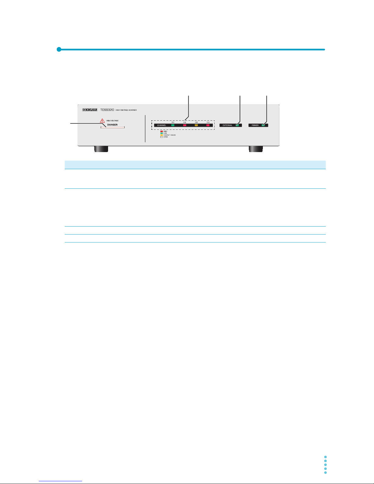
Front panel
No. Name Function See
1 DANGER LED Lights in sync with the TOS93 series tester when the power is turned on, when a test
is in progress, when a high voltage is being output, or when there is residual voltage
at the output terminals.
p. 9
2 CHANNEL
CH1/CH2/CH3/CH4 LED
Displays with different colors the status of each channel when a test is in progress.
• Red: Set to high.
• Green: Set to low.
• Orange: Contact being checked.
• Off: Set to open.
–
3 EXTERNAL LED Lights green when external control is enabled (EXTERNAL I/O is on). p. 25
4 POWER LED Lights green when the POWER switch is on. p. 14
1
2
34
8 User’s Manual TOS9320
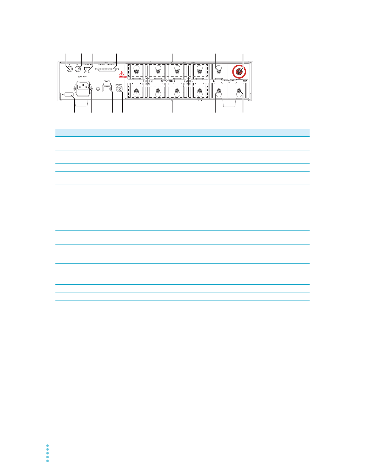
Rear panel
No. Name Function See
1 IN connector A connector for connecting to a TOS93 series tester. When connecting several
TOS9320 scanners in parallel, connect this to another TOS9320 scanner.
p. 17
2 OUT connector When connecting several TOS9320 scanners in parallel, connect this to another
TOS9320 scanner.
p. 17
3 EXTERNAL I/O switch Turns external control on and off. p. 25
4 CONTROLLER
INTERFACE connector
A I/O signal connector for controlling this product from an external device. p. 26
5 OUTPUT CH1-4
X terminals
High voltage terminals of each channel. Each channel can be set to an electric
potential of your choice (high, low, or open) from the TOS93 series tester.
p. 19
6 OUTPUT CH1-4
Y terminals
Low voltage terminals of each channel. Each channel can be set to an electric potential of your choice (high, low, or open) from the TOS93 series tester.
p. 19
7 IN HIGH VOLTAGE
terminal
A terminal for connecting this product to a TOS93 series tester or to another
TOS9320 scanner connected in parallel in order to receive the test voltage from the
TOS93 series tester. The test voltage is supplied at all times during a test.
p. 17
8 IN LOW terminal A terminal for connecting to a TOS93 series tester or another TOS9320 scanner con-
nected in parallel.
p. 17
9 OUT HIGH VOLTAGE
terminal
A terminal for supplying the test voltage received from the tester to another TOS9320
scanner when several TOS9320 scanners are connected in parallel. The test voltage
is supplied at all times during a test. Do not connect this terminal to the EUT.
p. 17
10 OUT LOW terminal A terminal for connecting to another TOS9320 scanner when several TOS9320 scan-
ners are connected in parallel.
p. 17
11 Serial number Serial number. –
12 AC INPUT inlet The power cord inlet for supplying power to this product. p. 13
13 POWER switch The power switch of this product. p. 14
14 GUARD terminal A terminal for connecting a chassis connection wire when a shield box is used. p. 22
8
9
11 10
123 4 5
6
7
12 13 14
TOS9320 User’s Manual 9
Safety Precautions for Testing
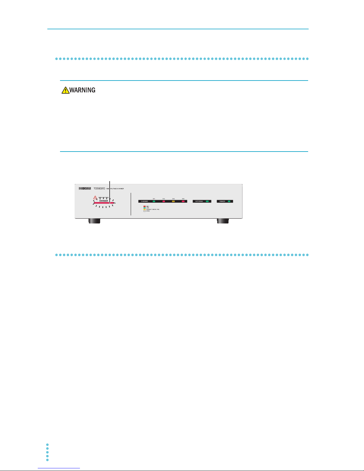
Lighting of the DANGER LED
The DANGER LED lights when the TOS9320 scanner is in any of the following conditions.
•At power on
• When a test is running
• When high voltage is being output
• When voltage remains at the output terminals
Check whether the DANGER LED lights at power on. If it does not, stop using the TOS9320 scanner, and
contact your Kikusui agent or distributor.
Test Precautions
Pre-test precautions
Check the following items before you start testing, and always follow the precautions.
• The power cord is connected to a properly grounded outlet.
• There is no damage such as tears or breaks in the test lead insulation.
• When the POWER switch is turned on, the DANGER LED lights.
• While the DANGER LED is lit, do not touch the items that are charged to a high voltage: the EUT,
the test leads, and the areas near the output terminals.
• When the DANGER LED is lit, do not turn the POWER switch off except in an emergency.
Risk of electric shock. The TOS9320 scanner supplies the 5.0 kVac, 7.2 kVdc, or higher
voltage received from the TOS93 series tester to external devices. Handling the product improperly may lead to a fatal accident. To prevent accidents, strictly follow the
precautions and always pay the utmost attention to safety concerns when you operate
the product.
10 User’s Manual TOS9320
Safety Precautions for Testing | Test Precautions
Testing precautions
During testing, the DANGER LED lights. Be careful because high voltage may be being output when the
DANGER LED is lit.
Precautions when changing test conditions
Before you change test conditions or other settings, press the tester’s STOP switch, and then be sure to
check the following items to ensure safety.
• The tester’s DANGER LED is off.
• The tester’s voltmeter is indicating “0.”
Risk of electric shock.
• While the DANGER LED is lit, it is dangerous to touch the items that are charged to
a high voltage: the EUT, the test leads, the probes, and the areas near the output terminals.
• Parts of the included test leads near the alligator clips protrude from the vinyl insulation when the wires are connected. These parts are dangerous. Never come close
to these parts while the DANGER LED is lit.
• During use, be sure to wear rubber gloves for electrical work. If obtaining these
gloves is difficult, contact your Kikusui agent or distributor.
Lit
TOS9320 User’s Manual 11
Safety Precautions for Testing
Precautions after Output Has Been Turned Off
During DC withstanding voltage tests and insulation resistance tests, the EUT, test leads, test probes, and
the area around the output terminals are all charged to a high voltage. After the output has been turned off,
be sure to check the following before you touch the items that have been charged to a high voltage.
• The tester’s DANGER LED is off.
• “RISE,” “TEST,” or “FALL” is not shown on the display.
• The tester’s voltmeter is indicating “0.”
If you will not use the product for some time or if the operator will be away from the product, be sure to turn
the tester’s POWER switch off.
Risk of electric shock.
• For a while after the output has been turned off, do not touch the items that have
been charged to a high voltage, such as the EUT, the test leads, the test probes, and
the areas near the output terminals.
• After the output has been turned off, the TOS93 series tester’s internal discharge
circuit goes into operation and discharges the output voltage. During testing and
before this discharge completes, do not disconnect the tester from the EUT.
12 User’s Manual TOS9320
Safety Precautions for Testing
Malfunction Precautions
Dangerous malfunctions
If the product is in one of the states explained below, it may be malfunctioning in a very dangerous manner—it may not be possible to turn off the high voltage that is being generated.
• Even when you press the tester’s STOP switch, the DANGER LED remains lit.
• Even though a voltage is indicated on the tester’s voltmeter, the DANGER LED does not light.
If the tester is not operating properly, it may be generating a high voltage irrespective of the settings made
by the operator. Immediately turn off the tester’s POWER switch, and disconnect the power cord from the
outlet. Further, turn off the TOS9320 scanners’ POWER switches, disconnect the power cords, stop using
the system immediately, and contact your Kikusui agent or distributor.
Emergency measures
There are two actions that you must carry out if, due to a malfunction in the test system or the EUT, there
is a possibility of an emergency occurring such as electric shock or damage to the EUT.
• Turn off the tester’s POWER switch.
• Remove the tester’s power cord plug from the outlet.
Then, turn off the TOS9320 scanners’ POWER switches, and disconnect the power cords from the outlet.
Risk of electric shock.
• Until you get the product fixed, make sure that nobody can use it.
• For repairs, contact your Kikusui agent or distributor.
 Loading...