

Kikusui TOS9300, TOS9302, TOS9301, TOS93 Series, TOS9303LC User Manual
...
TOS9300
TOS9301
TOS9302
TOS9303
TOS9303LC
User’s Manual
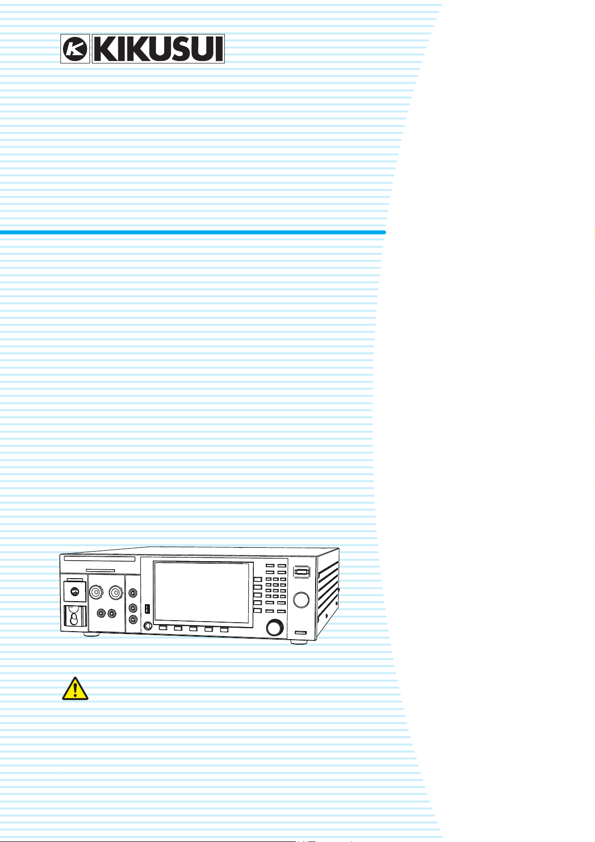
Electrical Safety Analyzer
TOS93 Series
DANGER
This product generates high voltage!
Improper operation can lead to serious accidents.
To prevent accidents, be sure to read the section
“Safety Precautions for Testing” in this manual.
Keep this manual close to the product so that the operators
can read the manual at any time.
Part No. IB032282
Dec 2018
Contents 7
Component Names 12
Safety Precautions for Testing 18
Installation 24
Basic Operation 42
Withstanding Voltage and Insulation
Resistance Tests 49
Earth Continuity Test 85
Touch Current Test 102
Protective Conductor Current Test 126
Patient Leakage Current Test 145
Meter Mode 168
Auto Test 182
External Control 199
Memory Function 213
System Settings 219
Maintenance 239
Specifications 245
Appendix 269
Testing is not possible upon opening the package
When you first turn on this product after opening the package, the safety interlock will prevent
you from performing tests. Connect the included SIGNAL I/O plug to the SIGNAL I/O connector
to temporarily release the interlock (p. 204).
When you actually perform tests, design a system that uses the interlock for safety (p. 205).
Notes to the supervisor
• If the operators cannot understand the language used in this manual, translate the manuals
into the appropriate language.
• Make sure that the operators understand the information in this manual before they operate
this product.
• Keep this manual close to the product so that the operators can read the manual at any time.
You will receive a potentially fatal electric shock if:
• You touch an output terminal while output is being generated.
• You touch a test lead that is connected to an output terminal while output is being generated.
• You touch the EUT while output is being generated.
• You touch a location that is electrically connected to an output terminal while output is being
generated.
• You touch a location that is electrically connected to an output terminal immediately after output is turned off after a DC withstanding voltage test or insulation resistance test has been
performed.
DANGER
2 User’s Manual TOS93 Series

This manual provides an overview of the product and
About Manuals
PDFPDF
PaperPaper
PaperPaper
PDFPDF
notes on usage. It also explains how to configure it, operate it, perform maintenance on it, and so on. Read this
manual thoroughly before use, and use the product properly.
Intended readers
These manuals are intended for users of this product and
their instructors. The manuals assume that the reader has
knowledge about electric safety testing.
Manual construction
Copyright
Reproduction and reprinting of this operation manual,
whole or partially, without our permission is prohibited.
Both unit specifications and manual contents are subject to
change without notice.
© Copyright 2018 Kikusui Electronics Corporation
• User’s manual (this manual)
This document is intended for first-time users of this
product. It provides an overview of the product, notes on
usage, and specifications. It also explains how to connect the product, configure the product, operate the
product, perform maintenance on the product, and so
on.
• Communication Interface Manual
This document contains details about remote control.
The interface manual is written for readers with sufficient
basic knowledge of how to control measuring instruments using a PC.
• Setup Guide
This document is intended for first-time users of the
product. It gives an overview of the product, connecting
procedures, safety precautions etc. Please read this
manual before you operating the product.
• Safety Information
This document contains general safety precautions.
Keep them in mind and make sure to observe them.
PDF files are included in the accompanying CD-ROM. You
can view the PDF files using Adobe Reader.
PDFPDF
PDFPDF
Firmware versions that this manual covers
This manual applies to products with firmware versions
1.0X.
For information on how to check the firmware version, see
“Displaying the Device Information” (p. 238).
When contacting us about the product, please provide us
with:
The model (marked in the top section of the front panel)
Firmware version (p. 238)
The serial number (marked on the rear panel)
Trademarks
Microsoft is a registered trademark or trademark of Microsoft Corporation in the United States and/or other countries.
Other company names and product names used in this
manual are generally trademarks or registered trademarks
of the respective companies.
TOS93 Series User’s Manual 3
The TOS93 series is a electrical safety analyzer that can
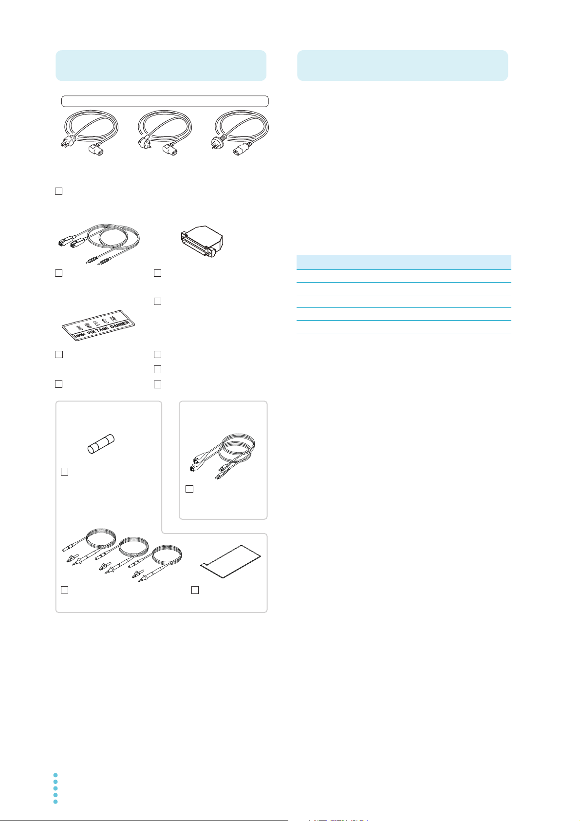
Accessories
High-voltage test lead
TL31-TOS (1 pair)
SIGNAL I/O plug (1 set)
Assembly type D-sub plug unit
Power cord (1 pc.,* length: 2.5 m)
* Two pieces included for the TOS9303LC.
CD-ROM (1 disc)
Setup Guide (1 copy)
Safety Information (1 copy)
Plug: CEE7/7
Rating: 250 Vac/10 A
[85-10-1070]
Plug: GB1002
Rating: 250 Vac/10 A
[85-10-0791]
or or
The attached power cord varies depending on the shipment destination.
High-voltage warning
sticker (1 pc.)
Test leads for earth
continuity test
TL13-TOS (1 pair)
TOS9302, TOS9303,
TOS9303LC only
Test leads for leakage current test
TL22-TOS (2 red, 1 black)
Flat probe
FP01-TOS (1 sheet)
TOS9303LC only
Spare fuse (1 pc.)
15 A, 250V
* Stored in the fuse holder
Plug: NEMA5-15
Rating: 125 Vac/10 A
[85-AA-0003]
Heavy object warning label
(1 pc.)*
Affix this to the product as
necessary.
* Not included with the TOS9300
Cable tie (1 pc.)
Product Overview
perform several types of safety tests on electronic devices
and components. The available types of safety tests
include withstanding voltage test, insulation resistance
test, earth continuity test, leakage current test (touch current test, and protective conductor current test, patient
leakage current test).
Different models are available according to the combination of tests you require, so a single unit is enough to cover
your various safety test needs.
The product is suited to (1) research and development
installations, (2) test facilities for quality assurance testing
and standard certification, and (3) manufacturing lines.
TOS93 Series Lineup
Model
TOS9300 ACW, IR
TOS9301 ACW, DCW, IR
TOS9302 ACW, EC
TOS9303 ACW, DCW, IR, EC
TOS9303LC ACW, DCW, IR, EC, LC
1 ACW: AC withstanding voltage, DCW: DC withstand-
ing voltage, IR: insulation resistance, EC: earth continuity, LC: leakage current
Supported tests
1
Features
Diverse lineup of products
A diverse lineup of products is available for the various
combinations of test required in production lines to
accommodate a variety of needs. Tests can be performed in accordance with the requirements of safety
and electrical standards and ordinances such as IEC,
EN, BS, VDE, UL, CSA, GB, and JIS.
Dielectric breakdown detection sensitivity settings
Safety standards define that corona discharge and partial discharge are not dielectric breakdown. This product
allows you to adjust the detection sensitivity of EUT’s
dielectric breakdown during withstanding voltage testing
to support a wide range of settings from those that do
not detect corona discharge or partial discharge to those
that do. Failure analysis that were not possible with previous Kikusui withstanding voltage testers is now possible.
Support for AC/DC earth continuity test up to 40 A
(TOS9302, TOS9303, TOS9303LC only)
The newly developed amplifier a broad range of tests
from AC earth continuity test of general home electric
appliances to DC earth continuity test of EV-PV systems.
A single unit for safety standard testing
(TOS9303LC only)
A single TOS9303LC, which includes all functions necessary for AC/DC withstanding voltage testing, insulation resistance testing, AC/DC earth continuity testing,
and leakage current testing, can perform the entire set
of safety standard conformance tests.
4 User’s Manual TOS93 Series
Support for touch current, protective conductor
Notations Used in This Manual
9300
9301
9302
9303
9303LC
Safety Precautions
current, and patient leakage current tests
(TOS9303LC only)
Various leakage current tests for medical instruments
are supported in addition to those for general electric
appliances.
LAN, USB, and RS232C
The product is standard equipped with LXI compatible
LAN, USB 2.0, USB-TMC compatible USB, and
RS232C interface.
Color liquid crystal display
Intuitive display and controls are provided through the 7inch display that shows various test settings, descriptions, and drawings.
• In this manual, the TOS9300, TOS9301, TOS9302,
TOS9303, and TOS9303LC electrical safety analyzer
are also referred to as the TOS93 series.
• The term “PC” is used to refer generally to both personal
computers and workstations.
• The term “EUT” is used to refer generally to an equipment under test.
• Test names may be abbreviated as follows:
AC withstanding voltage: ACW, DC withstanding voltage: DCW, insulation resistance: IR, earth continuity:
EC, leakage current: LC, touch current: TC, protective
conductor current: PCC, patient leakage current: Patient
• The screen captures and illustrations used in this text
may differ from the actual items.
• The following markings are used in this manual.
Indicates an imminently hazardous situation which,
if ignored, will result in death or serious injury.
Indicates a potentially hazardous situation which, if
ignored, could result in death or serious injury.
Indicates a potentially hazardous situation which, if
ignored, may result in slight injury or damage to the
product or other property.
Indicates information that you should know.
Indicates a reference manual (CD-ROM) containing
detailed information.
>
Indicates the hierarchy of items you need to select. The
item to the left of this symbol indicates a higher level
item.
, , , ,
Indicate TOS93 series model names.
9303
When using this product, be sure to observe the precautions in the Safety Information manual. Items specific to
this product are given below.
• This product generates high voltage. Improper operation can lead to serious accidents.
To prevent accidents, be sure to read “Safety Precautions for Testing” (p. 18) in this manual. Keep this manual close to the product so that the operators can read
the manual at any time.
• You will receive a potentially fatal electric shock if:
• You touch an output terminal while output is being
generated.
• You touch a test lead that is connected to an output
terminal while output is being generated.
• You touch the EUT while output is being generated.
• You touch a location that is electrically connected to
an output terminal while output is being generated.
• You touch a location that is electrically connected to
an output terminal immediately after output is turned
off after a DC withstanding voltage test or insulation
resistance test has been performed.
• You may receive a potentially fatal electric shock if:
• You operate the tester without grounding it.
• You operate the tester without using rubber gloves for
electrical work.
• You come close to a location that is electrically connected to an output terminal while output is being generated.
• You come close a location that is electrically connected to an output terminal immediately after output
is turned off after a DC withstanding voltage test or
insulation resistance test has been performed.
• In tests that use test leads, do not touch the tip of
test leads.
Risk of electric shock.
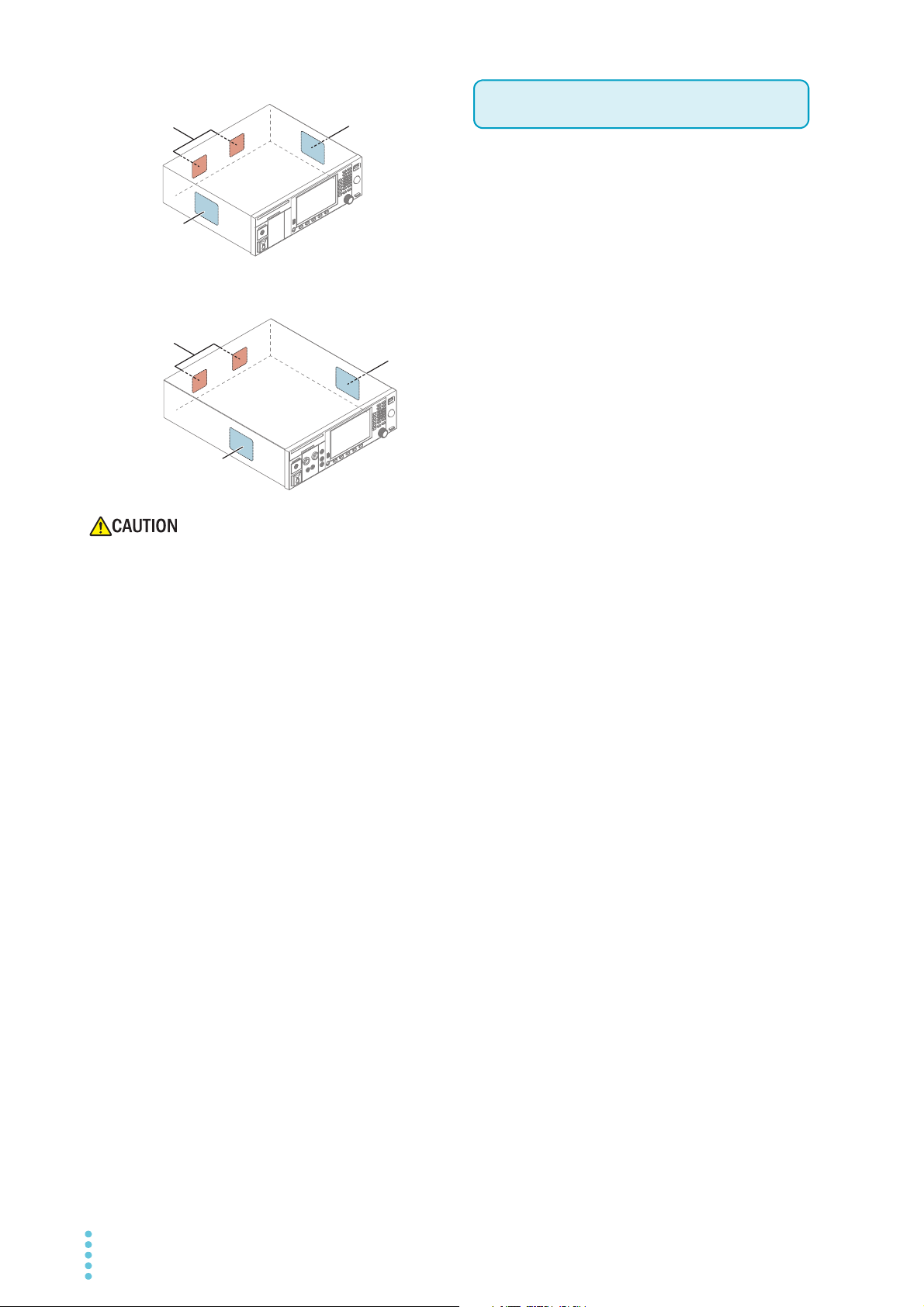
• Do not use the product in a poorly ventilated location.
The product uses forced air cooling. It sucks air through
the inlet holes on its right and left panels and expels air
through its rear panel. Secure adequate space around
the product’s inlet and outlet holes to prevent the possibility of fire caused by accumulation of heat.
Allow at least 20 cm of space between the air inlet/outlet
and the wall (or obstacles). Be careful not to block the
air inlet and outlet when rack mounting the product.
Hot air (approximately 20 °C, 68 °F, hotter than the
ambient temperature) is expelled from the outlet holes.
Do not place objects that are affected by heat near the
air outlet.
TOS93 Series User’s Manual 5
• Do not use this product near highly sensitive mea-
Air outlet
Air inlet
Air inlet
Air outlet
Air inlet
Air inlet
TOS9300, TOS9301
TOS9302, TOS9303, TOS9303LC
Notes on Usage
suring instruments or receivers.
Noise generated by this product may affect other
devices. At a test voltage of 3 kV or greater, the product
may produce corona discharge between its test lead
clips. This will generate a significant amount of broadband RF emission. To minimize this effect, keep the alligator clips away from each other. Also, keep the alligator
clips and test leads away from conducting surfaces,
especially sharp metal edges.
• When installing this product, be sure to observe the temperature and humidity ranges indicated below.
Operating temperature range: 0 °C to 40 °C (32 °F to
104 °F)
Operating humidity range: 20 %rh to 80 %rh (no condensation)
• When storing this product, be sure to observe the temperature and humidity ranges indicated below.
Storage temperature range: -20 °C to 70 °C (-4 °F to
158 °F)
Storage humidity range: 90 %rh or less (no condensation)
6 User’s Manual TOS93 Series

+
Contents
About Manuals ...................................................3
Accessories ........................................................4
Product Overview ...............................................4
Notations Used in This Manual...........................5
Safety Precautions .............................................5
Notes on Usage..................................................6
Component Names ..........................................12
Safety Precautions for
Testing
Lighting of the DANGER LED...........................18
Test Precautions ..............................................18
Pre-test precautions ............................................. 18
Testing precautions .............................................. 19
Precautions when setting test conditions ............. 19
Precautions after Output Has Been Turned Off20
Estimated discharge time ..................................... 20
Remote Control Precautions ............................21
Malfunction Precautions ...................................21
Dangerous malfunctions ....................................... 21
Emergency measures........................................... 21
Protection Functions.........................................22
Installation
Connecting the Power Cord .............................24
Checking Whether the Power Is On or Off .......25
Checking the interlock operation .......................... 25
Turning the power on............................................ 26
Turning the power off............................................ 27
Connection for Withstanding Voltage and Insula-
tion Resistance Tests .......................................28
Connecting the test leads ..................................... 28
Removing the test leads ....................................... 32
Connection for Earth Continuity Tests..............33
Four-terminal wiring and two-terminal wiring ........ 33
Connecting the test leads ..................................... 34
Removing the test leads ....................................... 36
Connection for Leakage Current Tests.............37
Using the insulation transformer........................... 37
Connecting the EUT to the power supply ............. 37
Connecting the test leads..................................... 40
Basic Operation
Basic Panel Operations.................................... 42
Switching menus .................................................. 42
Using the function keys ........................................ 43
Inputting numbers and characters........................ 45
Changing values................................................... 46
Selecting the Test Mode .................................. 47
Selecting the test mode........................................ 48
Withstanding Voltage and
Insulation Resistance Tests
Setting Test Conditions ....................................49
Displaying the setup screen (Home menu) .......... 49
Description of test conditions ............................... 50
Test voltage.......................................................... 51
Limit voltage ......................................................... 52
Start voltage ......................................................... 53
Frequency ............................................................ 54
Upper limit ............................................................ 55
Lower limit ............................................................ 56
Unit of criteria (Judge Type) ................................. 57
Auto setting of the judgment delay (Delay Auto) .. 58
Test time............................................................... 60
Voltage rise time................................................... 61
Voltage fall time.................................................... 62
Discharge time ..................................................... 63
Discharge when interlock is activated (Discharge In-
terlock).................................................................. 64
Current detection response speed (Filter)............ 65
Grounding mode (GND) ....................................... 66
Current measurement mode (Current RMS) ........ 68
Voltage measurement mode (Volt Measure)........ 69
Peak value display (Display Peakhold) ................ 70
Using the low-pass filter ....................................... 71
Offset (Offset Real, Offset Imag).......................... 72
Offset.................................................................... 73
Checking the scanner contact (Contact Check) ... 74
Setting scanner channels (Edit) ........................... 75
Opening the scanner (All Open)........................... 76
TOS93 Series User’s Manual 7

Starting a Test ................................................. 77
Output time limit ....................................................77
Starting a test ........................................................78
Operation after a test starts...................................79
Changing the voltage setting during a test ............82
Finishing the Test and Viewing the Judgment.83
Stopping tests .......................................................83
Conditions that cause a test to end .......................83
Judgment types and operation ..............................84
Clearing the judgment result .................................84
Earth Continuity Test
Setting Test Conditions ................................... 85
Displaying the setup screen (Home menu) ...........85
Description of test conditions ................................86
Test current ...........................................................86
Limit current ..........................................................87
Frequency .............................................................87
Upper limit .............................................................88
Lower limit.............................................................89
Test time ...............................................................90
Current rise time....................................................91
Current fall time .....................................................91
Terminal wiring method (Terminals Wire) .............92
Contact check .......................................................93
Peak value display (Display Peakhold) .................94
Offset.....................................................................95
Starting a Test ................................................. 96
Output time limit ....................................................96
Starting a test ........................................................96
Operation after a test starts...................................97
Changing the current setting during a test ............99
Finishing the Test and Viewing the Judgment100
Stopping tests .....................................................100
Conditions that cause a test to end .....................100
Judgment types and operation ............................101
Clearing the judgment result ...............................101
Touch Current Test
Setting Test Conditions ................................. 102
Displaying the setup screen (Home menu) .........102
Description of test conditions ..............................103
Network ...............................................................104
Polarity of the power supply line .........................105
Single fault mode (Condition) ..............................106
Probe connection destination ..............................107
Output from the 110% terminal (110% OUT) ......108
Upper limit ...........................................................109
Lower limit...........................................................110
Judgment delay (Judge Delay) ...........................111
Test time .............................................................112
Measurement range............................................113
Measurement mode (Measure Mode).................115
Voltmeter band expansion (VoltMeter BandWidth) ...
116
Peak value display (Display Peakhold) ...............117
Measurement check (Measure Check) ...............117
Offset .................................................................. 118
Voltage conversion (Conv Voltage) ....................119
Checking the EUT operation (Line OUT) ............ 119
Starting a Test................................................120
Connecting the test leads to the EUT ................. 120
Starting a test...................................................... 121
Operation after a test starts ................................122
Finishing the Test and Viewing the Judgment124
Stopping tests .....................................................124
Conditions that cause a test to end.....................124
Judgment types and operation............................125
Clearing the judgment result ...............................125
Protective Conductor
Current Test
Setting Test Conditions ..................................126
Displaying the setup screen (Home menu) .........126
Description of test conditions ..............................127
Network...............................................................128
Polarity of the power supply line .........................129
Single fault mode (Condition)..............................129
Upper limit...........................................................130
Lower limit...........................................................131
Judgment delay (Judge Delay) ...........................132
Test time .............................................................133
Measurement range............................................134
Measurement mode (Measure Mode).................135
Voltmeter band expansion (VoltMeter BandWidth) ...
136
Peak value display (Display Peakhold) ...............137
Measurement check (Measure Check) ...............137
Offset .................................................................. 138
Voltage conversion (Conv Voltage) ....................139
Checking the EUT operation (Line OUT) ............ 139
Starting a Test................................................140
Starting a test...................................................... 140
Operation after a test starts ................................141
Finishing the Test and Viewing the Judgment143
Stopping tests .....................................................143
Conditions that cause a test to end.....................143
Judgment types and operation............................144
Clearing the judgment result ...............................144
8 User’s Manual TOS93 Series

Patient Leakage Current
Test
Setting Test Conditions ..................................145
Displaying the setup screen (Home menu) ........ 145
Description of test conditions.............................. 146
Network .............................................................. 146
Polarity of the power supply line ......................... 147
Single fault mode (Condition) ............................. 148
Probe connection destination ............................. 149
Output from the 110% terminal (110% OUT) ..... 150
Upper limit .......................................................... 151
Lower limit .......................................................... 152
Judgment delay (Judge Delay) ........................... 153
Test time............................................................. 154
Measurement range ........................................... 155
Measurement mode (Measure Mode) ................ 156
Voltmeter band expansion (VoltMeter BandWidth) ..
157
Peak value display (Display Peakhold) .............. 158
Measurement check (Measure Check)............... 158
Offset .................................................................. 159
Voltage conversion (Conv Voltage) .................... 160
Checking the EUT operation (Line OUT)............ 160
Starting a Test ................................................161
Connecting the test leads to the EUT................. 161
Starting a test ..................................................... 163
Operation after a test starts ................................ 164
Finishing the Test and Viewing the Judgment166
Stopping tests..................................................... 166
Conditions that cause a test to end .................... 166
Judgment types and operation ........................... 167
Clearing the judgment result............................... 167
Meter Mode
Connecting the test leads................................... 179
Taking measurements........................................ 179
Measurement operation ..................................... 180
Measurement example (judgment of the parts that
can be touched).................................................. 180
Auto Test
Auto Test Overview........................................182
Tests that auto test can run................................ 182
Programs and steps ........................................... 182
Main functions .................................................... 183
Program Configuration ...................................184
Displaying the program editing screen ............... 184
Creating a program ............................................ 185
Changing a program name................................. 185
Deleting a program............................................. 186
Setting Steps..................................................187
Displaying the step editing screen...................... 187
Editing steps....................................................... 188
Program Operation Configuration ..................189
Fail judgment operation (FAIL Judgment) .......... 189
Step interval ....................................................... 190
Step start operation (Trigger Source) ................. 191
EUT power supply (Line Break) ......................... 192
Running Auto Tests........................................193
Running an auto test.......................................... 193
Behavior during the test ..................................... 194
Finishing the Test and Viewing the Judgment195
Stopping tests..................................................... 195
Conditions that cause a test to end .................... 195
Judgment types and operation ........................... 196
Clearing the judgment result .............................. 196
Exporting and Importing Programs ................197
Exporting programs to a USB memory device ... 197
Importing programs from a USB memory device 198
Constructing the Measurement Circuit ...........169
Setting Measurement Conditions ...................170
Displaying the setup screen (Home menu) ........ 170
Overview of measurement conditions ................ 170
Network .............................................................. 171
Measuring across terminals A and B (A-B Terminal)
172
SELV setting....................................................... 173
Measurement range ........................................... 174
Measurement mode (Measure Mode) ................ 175
Measurement check (Measure Check)............... 175
Offset .................................................................. 176
Output from the 110% terminal (110% OUT) ..... 177
Polarity of the 110% output ................................ 178
Executing a Measurement ..............................179
TOS93 Series User’s Manual 9
External Control
SIGNAL I/O Connector...................................200
Pin arrangement................................................. 200
I/O signal circuit.................................................. 201
Input signal usage example................................ 202
Output signal usage example............................. 202
Connecting to the SIGNAL I/O connector .......... 203
Activating and Releasing Interlock ................. 204
Interlock activation conditions ............................ 204
Interlock release conditions................................ 204
Examples of how to use interlock....................... 205
Recalling from memory ..................................206

Starting and Stopping Tests .......................... 207
Starting a test ......................................................207
Stopping a test ....................................................207
Monitoring the Test Status............................. 208
Monitoring the test mode.....................................208
Monitoring the test and voltage generation status ....
208
Monitoring the test status ....................................208
Monitoring judgment results ................................209
Monitoring the step execution status of auto tests ....
210
Monitoring the activation status of protection func-
tions.....................................................................210
Monitoring Measurements............................. 211
Monitoring current waveforms .............................211
Monitoring voltage waveforms ............................211
Using Option Products................................... 212
Signal output from the STATUS OUT connector.212
Signal I/O of the REMOTE connector .................212
Initializing the Settings....................................235
Restoring the factory default settings..................235
Restoring the reset settings ................................236
Updating.........................................................237
Displaying the Device Information..................238
Maintenance
Inspection.......................................................239
Pre-inspection for withstanding voltage test and insu-
lation resistance test ...........................................239
Pre-testing the earth continuity test ....................240
Pre-testing the leakage current test ....................241
Replacing Components .................................. 243
Replacing the backup battery .............................243
Replacing the fuse ..............................................243
Periodic Calibration ........................................244
Memory Function
Saving and Recalling Test Conditions........... 213
How to view the setup memory screen ...............213
Saving to the setup memory ...............................214
Checking the setup memory details ....................215
Recalling the setup memory................................216
Saving and Viewing Test Results .................. 217
Displaying a list of test results.............................217
Saving test results to a USB memory device ......218
Clearing the list of test results .............................218
System Settings
Displaying and Changing CONFIG Settings.. 219
Panel settings at startup (Power On) ..................220
Operation when there is no SCPI communication
(Watchdog)..........................................................221
Screen saver .......................................................222
Key lock...............................................................223
Calibration configuration .....................................224
Beep sound (Beeper) ..........................................225
Fail mode ............................................................226
Test start settings................................................227
PASS judgment result hold time .........................228
STATUS OUT setting (Status Output) ................229
Outputting judgment for each step (Step END Judg-
ment) ...................................................................230
Displaying/Changing the Interface Settings... 231
Displaying SCPI Errors.................................. 233
Setting the Date/Time.................................... 234
Specifications
Withstanding voltage test section .......................246
Insulation resistance test section ........................249
Earth continuity test section ................................253
Leakage current test section...............................255
Interface ..............................................................262
Other functions.................................................... 263
General specifications.........................................265
External dimensions............................................266
Appendix
Default Settings and Reset Settings...............269
Withstanding voltage (ACW/DCW), insulation resis-
tance (IR) test conditions ....................................269
Earth continuity (EC) test conditions ...................270
Leakage current (LC) test conditions .................. 270
Auto test (AUTO) settings ...................................272
Memory function .................................................272
CONFIG settings.................................................273
Interface settings.................................................274
Stray Capacitance of AC Withstanding Voltage
Tests...............................................................275
Timing Charts .................................................276
Contact check operation .....................................276
ACW test (PASS judgment) ................................277
ACW test (FAIL judgment) ..................................278
ACW test (interlock) ............................................ 279
Options...........................................................280
High voltage scanner ..........................................280
10 User’s Manual TOS93 Series

Remote control box ............................................ 281
DIN adapter cable............................................... 281
High voltage test probe....................................... 282
Warning light unit ................................................ 282
Multi-outlet .......................................................... 283
Brackets.............................................................. 284
Troubleshooting..............................................285
Index...............................................................287
TOS93 Series User’s Manual 11
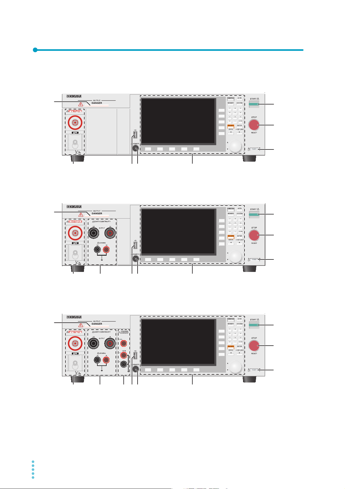
Component Names
56
1
56 7
2
1
1
2
8
9
3
7
8
9
8
9
Front panel
TOS9300, TOS9301
10
TOS9302, TOS9303
TOS9303LC
10
2
3456 7
10
12 User’s Manual TOS93 Series

No. Name Function See
DANGER LED Lights red when the power is turned on, when a test is in progress, when
1
–
a high voltage is being output, or when there is residual voltage at the
output terminals. On the TOS9303LC, the LED also lights red when supply voltage is being supplied to the EUT.
Area for withstanding voltage,
2
–
p.28
insulation resistance
HIGH VOLTAGE terminal Outputs the test voltage of the high voltage side. –
LOW terminal Outputs the test voltage of the low voltage side (with cable lock). –
Area for earth continuity test –
3
p.33
OUTPUT HI terminal Outputs the test voltage of the high voltage side. –
OUTPUT LO terminal Outputs the test voltage of the low voltage side. –
SENSING HI terminal Detects the voltage at the sensing terminal (of the high voltage side)
–
when four-terminal wiring is in use.
SENSING LO terminal Detects the voltage at the sensing terminal (of the low voltage side) when
–
four-terminal wiring is in use.
Area for leakage current test –
4
p.37
110% terminal Outputs 110 % voltage. –
A and B terminals Measurement terminals for connecting test leads and probes. –
USB port (host)
5
REMOTE connector For connecting the optional remote control box or test probes.
6
Controls –
7
START switch Starts a test. –
8
STOP switch Stops testing and clears the current status. Returns to the HOME menu
9
For connecting an external keyboard.
Saves setup memory and test results.
Exporting and Importing Programs.
Updates the firmware.
p.45
p.213
p.197
p.237
p.280
p.14
–
screen.
POWER switch
10
Turns the power on (
) and off( ).
p.26
TOS93 Series User’s Manual 13
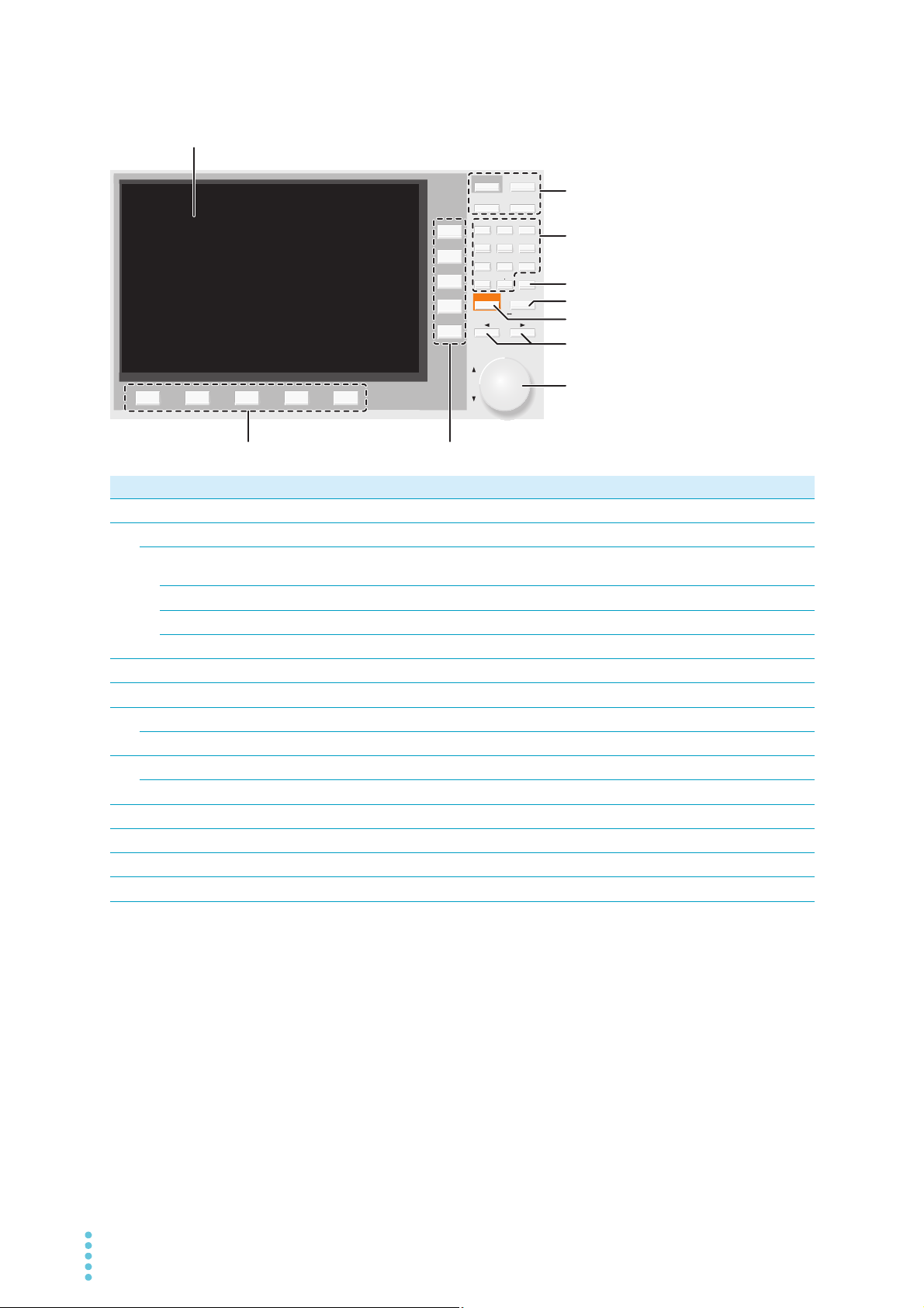
Controls
AUTO
MEMORY
SYSTEM
ENTERESCAPE
879
546
213
0CLEAR
LOCAL
KEY LOCK
HOME/FUNC
1
910
2
3
6
7
8
5
4
No. Name Function See
Display Displays the settings, measured values, and other information.
1
Menu keys Switch the display.
2
HOME/FUNC key Switches between the test setup screen (Home menu) and test selection
screen (Function menu).
AUTO key Displays the auto test screen.
MEMORY key Displays the memory function screen.
SYSTEM key Displays the system setting screen (System Menu).
Numeric keypad Enters values.
3
CLEAR key Deletes numbers/characters.
4
ENTER key Confirms numeric keypad input. Confirmation after selection of setting item.
5
KEYLOCK key Hold down to lock the keys. Hold down when key lock is enabled to unlock.
ESCAPE key Cancels numeric/character input. Closes windows.
6
LOCAL key Returns remote control to panel operation.
←/→ keys Move the cursor left and right. Select the left or right item.
7
Rotary knob Selects an item. Enters numbers and characters.
8
Function keys Executes the item that is displayed above each key (function area).
9
Sub-function keys Executes the item that is displayed to the left of each key (sub-function area).
10
p.15
p.42
p.42
p.182
p.213
p.219
p.45
p.45
p.45
p.223
p.45
p.285
p.45
p.45
p.43
p.43
14 User’s Manual TOS93 Series
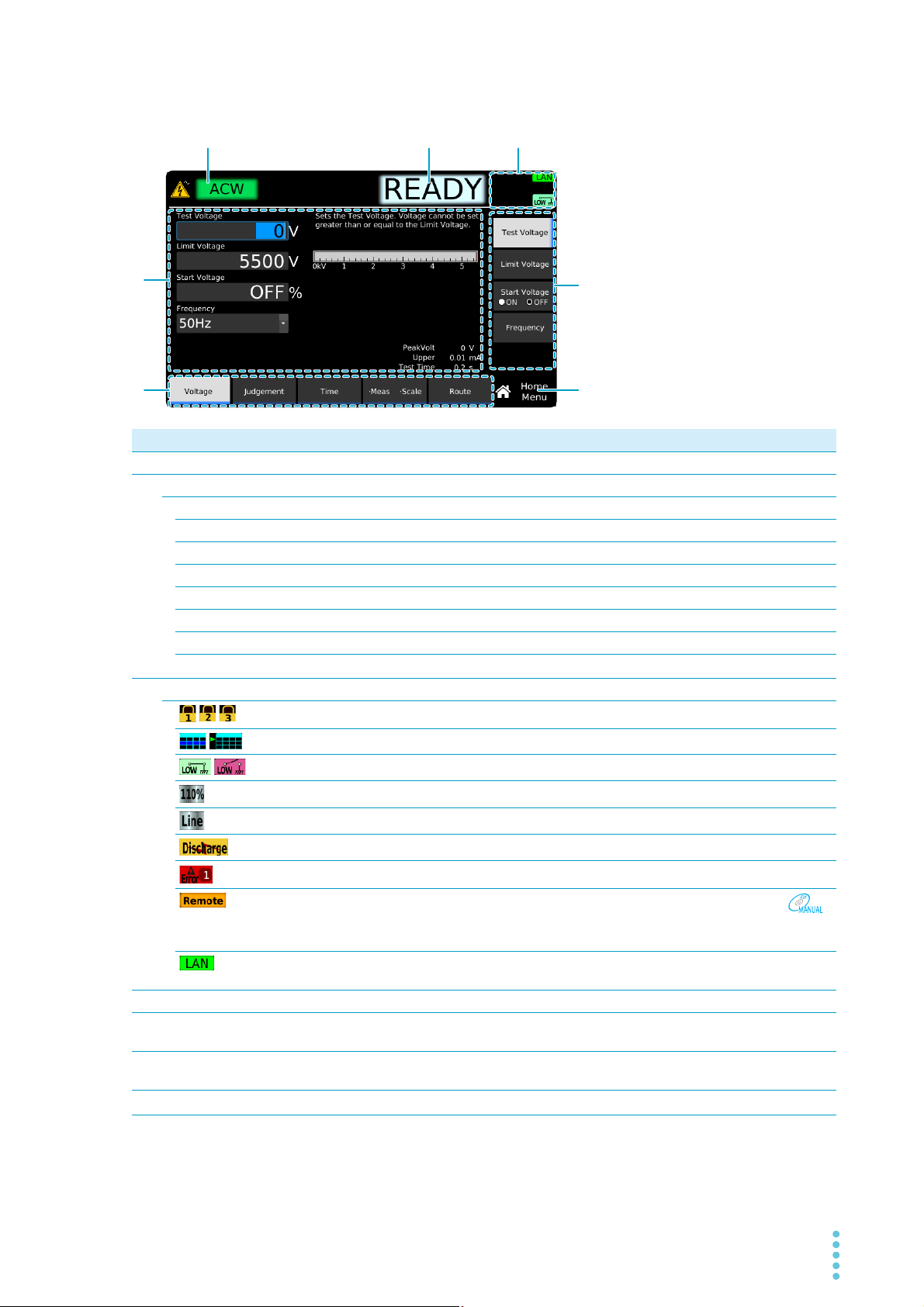
Display
123
4
5
6
7
No. Name Function See
Test mode Selected test type. –
1
Test status. – –
2
READY Ready to start test. –
RISE Voltage or current rising. –
FALL Voltage or current falling. –
TEST Testing. –
PASS Test successful. –
U-FAIL
L-FAIL Test failed because a value less than or equal to the lower limit was detected. –
CHECK Contact check in progress.
Status display icon area.
3
//
/
/
Settings area
4
function area Indicates that execution is possible with the keys (function keys) at the bottom
5
sub-function area Indicates that execution is possible with the keys (sub-function keys) in the
6
Menu name Name of the menu currently displayed.
7
Test failed because a value greater than or equal to the upper limit was detected.
– –
Indicates that key lock is on. The key lock level is displayed numerically.
Auto testing/auto test standby.
GND setting (Low, Guard).
Applying voltage from the 110 % terminal.
Supplying power to the EUT from the AC LINE OUT terminal block.
While discharging.
SCPI error. The number of error incidents (up to 16) is displayed numerically.
Under remote control.
LAN connection status. Green: Communication enabled, Orange: Preparing for
communication, Red: Not connected.
Displays settings and descriptions. Displays measured values during testing.
of the display.
right side of the display.
–
p.93
p.223
p.182
p.66
p.177
p.242
p.63
p.233
Interface
Manual
–
–
p.43
p.43
p.42
TOS93 Series User’s Manual 15
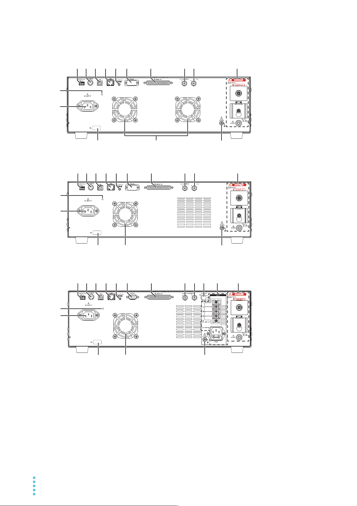
Rear panel
123 4 567 98
14
14
14
123 4 56 7 10 11 12
12
12
13
15
15
15
123 4 567
16 17
1716
16 17
89
89
13
13
TOS9302, TOS9303
TOS9303LC
TOS9300, TOS9301
16 User’s Manual TOS93 Series

No. Name Function See
STATUS OUT connector Connect option products.
1
SCANNER connector Connect to the high voltage scanner option.
2
USB port USB port for remote control.
3
LAN port LAN port for remote control.
4
RS232C port RS232C port for remote control.
5
DC OUT 5 V terminal Connect option products. –
6
SIGNAL I/O connector A I/O signal connector for controlling this product from an external
7
p.212
p.280
Interface
Manual
p.199
device.
I terminal Signal output terminal for monitoring the current waveforms of with-
8
p.211
standing voltage tests.
V terminal Signal output terminal for monitoring the voltage waveforms of with-
9
p.211
standing voltage tests.
CAL terminal Not used. –
10
Area for leakage current test –
11
AC LINE OUT terminal block Connect the EUT here. Power applied to the AC LINE IN inlet is
p.37
–
supplied.
AC LINE IN inlet Connect a power cord for supplying power to the EUT. –
FUSE Input fuse holder for the EUT power supply.
Area for withstanding voltage,
12
–
p.243
p.28
insulation resistance
HIGH VOLTAGE terminal Outputs the test voltage of the high voltage side. –
LOW terminal Outputs the test voltage of the low voltage side (with cable lock). –
GUARD terminal Connect the chassis connection wire of the shield box when a shield
box is used.
Cable tie attachment hole Hole for attaching the included cable tie (for USB cables). –
13
AC INPUT inlet Connect a power cord for supplying power to this product.
14
Serial number Serial number. –
15
Air outlet Vent for cooling this product. –
16
FOR OPTION terminal Connect the ground wire of option products. –
17
p.31
p.24
TOS93 Series User’s Manual 17
Safety Precautions for Testing
WARNING
Lighting of the DANGER LED
The DANGER LED lights when the product is in any of the following conditions.
• At power on
• When a test is running
• When high voltage is being output
• When voltage remains at the output terminals
• When supply voltage is being supplied to the EUT (TOS9303LC only)
Check whether the DANGER LED lights at power on. If it does not, stop using the product, and contact
your Kikusui agent or distributor.
Test Precautions
Pre-test precautions
Risk of electric shock. In a AC withstanding voltage test, the TOS93 series generates a
maximum voltage of 5.0 kVac. In a DC withstanding voltage test, the TOS9301,
TOS9303, and TOS9303LC generate a maximum voltage of 7.2 kVdc. Handling the
product improperly may lead to a fatal accident. To prevent accidents, strictly follow
the precautions and always pay the utmost attention to safety concerns when you
operate the product.
Check the following items before you start testing, and always follow the precautions.
• The power cord is connected to a properly grounded outlet.
• There is no damage such as tears or breaks in the test lead insulation.
• When the POWER switch is turned on, the DANGER LED lights.
• While the DANGER LED is lit, do not touch the items that are charged to a high voltage: the EUT,
the test leads, and the areas near the output terminals.
• When the DANGER LED is lit, do not turn the POWER switch off except in an emergency.
18 User’s Manual TOS93 Series
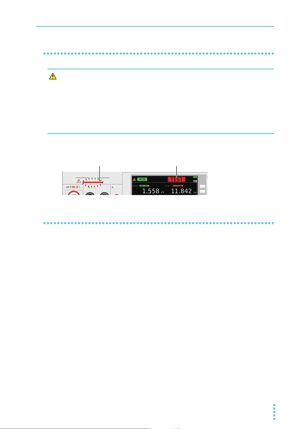
Testing precautions
WARNING
OUTPUT
DANGER
110%
LEAKAGE
CURRENT
HIGH VOLTAGE
EARTH CONTINUITY
OUTPUT
LOW HIGH
H
Lit Test status
Risk of electric shock.
• While the DANGER LED is lit, it is dangerous to touch the items that are charged to
a high voltage: the EUT, the test leads, the probes, and the areas near the output terminals.
• The alligator clip vinyl insulation of the supplied tests do not have dielectric
strength. Never touch these while the DANGER LED is lit.
• When performing a withstanding voltage test, be sure to wear rubber gloves for
electrical work. If obtaining these gloves is difficult, contact your Kikusui agent or
distributor.
During testing, the DANGER LED lights, and the display shows “TEST.” Be careful because high voltage
may be being output when the DANGER LED is lit.
Safety Precautions for Testing | Test Precautions
Precautions when setting test conditions
Before you set the test conditions or other settings, press the STOP switch, and then be sure to check the
following items to ensure safety.
• The DANGER LED is off.
• The voltmeter is displaying “0.”
TOS93 Series User’s Manual 19
Safety Precautions for Testing
WARNING
Precautions after Output Has Been Turned Off
Risk of electric shock.
• For a while after the output has been turned off, do not touch the items that have
been charged to a high voltage, such as the EUT, the test leads, the test probes, and
the areas near the output terminals.
• After the output has been turned off, the internal discharge circuit goes into operation and discharges the output voltage. During testing and before this discharge
completes, do not disconnect the tester from the EUT.
The EUT, test leads, test probes, and the area around the output terminals are all charged to a high voltage. After the output has been turned off, be sure to check the following before you touch the items that
have been charged to a high voltage.
• The DANGER LED is off.
• “RISE,” “TEST,” or “FALL” is not shown on the display.
• The voltmeter is displaying “0.”
If you will not use the product for some time or if the operator will be away from the product, be sure to turn
the POWER switch off.
Estimated discharge time
The time required to discharge the built-up electrical charge varies according to the test voltage and the
properties of the EUT.
The time that this product requires to discharge the voltage from its internal capacitors down to 30 V is as
follows:
• When an EUT is not connected: 16 ms for a DCW test, 1.5 ms for an IR test
• When an EUT with a input capacitance of 0.05 μF is connected: 50 ms for a DCW test, 6 ms for an IR
test
20 User’s Manual TOS93 Series
Safety Precautions for Testing
WARNING
Remote Control Precautions
If you are performing remote control at a location away from the product, to prevent accidents, follow the
safety measures given below.
• Make sure that high voltages are not generated unintentionally.
• Make it impossible to touch the EUT, test leads, test probes, and the areas near the output terminals when high voltages are being generated.
Malfunction Precautions
Risk of electric shock.
• Until you get the product fixed, make sure that nobody can use it.
• For repairs, contact your Kikusui agent or distributor.
Dangerous malfunctions
If the product is in one of the states explained below, it may be malfunctioning in a very dangerous manner—it may not be possible to turn off the high voltage that is being generated.
• Even when you press the STOP switch, the DANGER LED remains lit.
• Even though a voltage is indicated on the voltmeter, the DANGER LED does not light.
If the tester is not operating properly, it may be generating a high voltage irrespective of the settings made
by the operator. Immediately turn the POWER switch off, and disconnect the power cord from the outlet.
Stop using the product immediately, and contact your Kikusui agent or distributor.
Emergency measures
There are two actions that you must carry out if, due to a malfunction in the product or the EUT, there is a
possibility of an emergency occurring such as electric shock or damage to the EUT.
• Turn the POWER switch off.
• Remove the power cord plug from the outlet.
TOS93 Series User’s Manual 21
Safety Precautions for Testing
Protection Functions
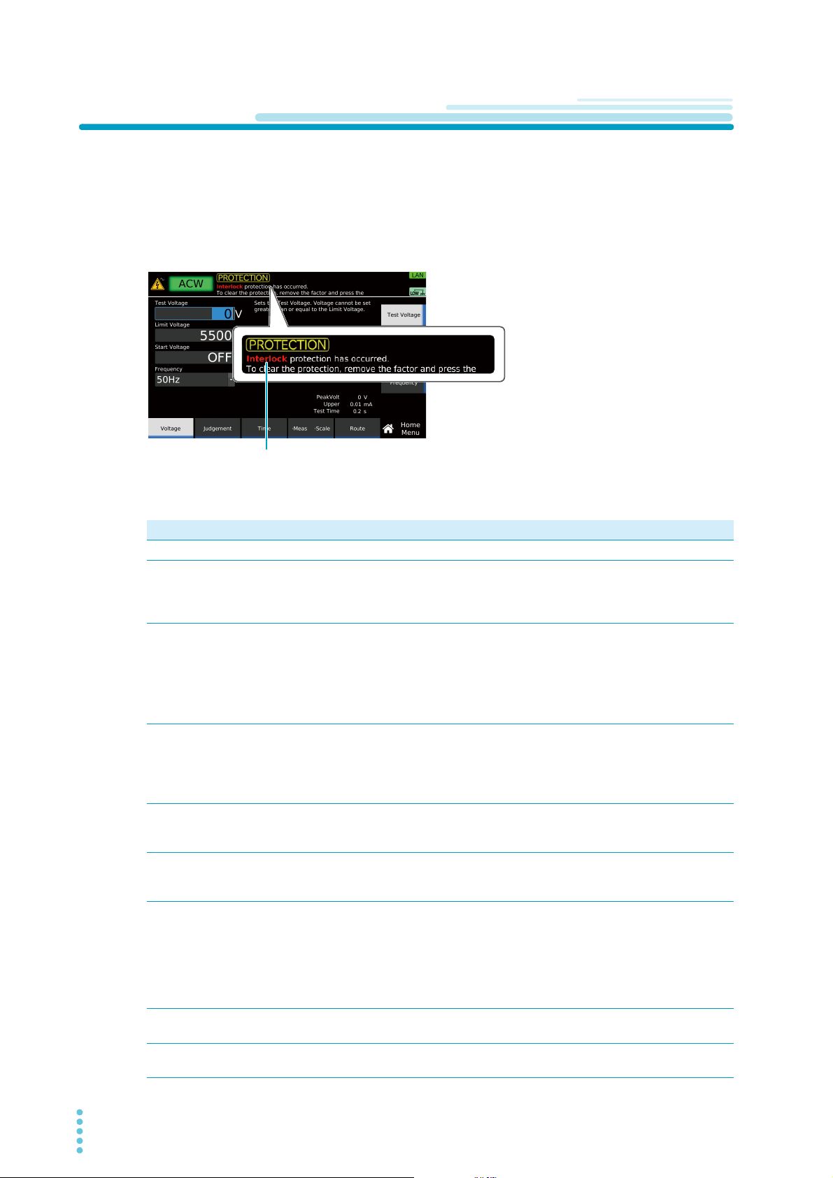
When one or more protection function activation conditions are met, the protection function will be activated, and you will no longer able to perform test in this state (PROTECTION mode).
When a protection function is activated, the word “PROTECTION” is indicated on the display along with
the type of protection. If a PROTECTION mode occurs during a test, the output is shut off and the test is
stopped immediately. If a leakage current (LC) test is in progress on the TOS9303LC, the power supply to
the EUT is stopped, and the A and B terminals are opened.
Type of protectionType of protection
Use the following table to check the type of protection function, activation condition, and remedy, and
release PROTECTION mode.
Type of protection Activation condition Remedy
Interlock Interlock is activated. Release the interlock (p.204).
Power Supply There is an error in the power supply section. Pressing STOP releases the PRO-
TECTION mode, but the product
needs to be repaired. Contact your
Kikusui agent or distributor.
Output Error An output voltage outside of the following range
is detected.
ACW, DCW, IR test: ±(10 % of setting + 10 V)
EC test: ±(10 % of setting + 5 A)
This error may also occur when the output
changes suddenly.
Over Load An output power outside of the following range is
detected.
ACW: 550 VA, DCW: 110 W, EC: 240 VA,
LC: AC LINE OUT current at approx. 15.75 A or
power at 1600 VA
Over Heat The internal temperature of the product is abnor-
mally high.
Over Rating During a withstanding voltage test, an output
current is generated for a length of time that
exceeds the output time limit (p.77).
Cal The preset calibration period is exceeded. Setting Protection under Calibration
Remote The REMOTE connector is connected or discon-
nected.
Signal I/O There is a change in the SIGNAL I/O connec-
tor’s ENABLE signal.
Eliminate the cause of the error, and
press STOP.
Eliminate the cause of the error, and
press STOP.
(TOS9303LC only) Disconnect the
EUT from AC LINE OUT, and press
STOP.
Confirm that the internal temperature
of the product has decreased, and
then press STOP.
Press STOP, and wait the necessary
rest time.
(p.224) to Disable and pressing
STOP releases the PROTECTION
mode, but the product needs to be
calibrated. To have your product calibrated, contact your Kikusui agent or
distributor.
Check the REMOTE connector, and
then press STOP.
Press STOP.
22 User’s Manual TOS93 Series

Safety Precautions for Testing | Protection Functions
Type of protection Activation condition Remedy
Communication An internal communication error is occurring. Repair is necessary. Turn the power
off, and contact your Kikusui agent or
distributor.
No SCPI communication took place for more
than the specified time when the watchdog
(p.221) was enabled.
Backup There is an error in the backup data due to a
dead battery or the like.
Over Range A value exceeding the maximum value of the
measurement range is detected.
Measure There is an error in the LC test measurement
check (p.241).
Short A relay operation error is detected in an LC test. Repair is necessary. Turn the power
Earth Fault When the grounding mode (GND) is set to
Guard, abnormal current flows from the high
voltage output of this product to ground.
Scan I/F While scanning, the interface cable is discon-
nected.
The channel-assigned scanner is not detected. Check the scanner connection, and
Check the SCPI communication status.
Repair is necessary. Turn the power
off, and contact your Kikusui agent or
distributor.
Eliminate the cause of the error, and
press STOP.
Press STOP, and check whether the
test leads are broken. If you perform
another measurement check and
“Measure” still appears, repairs are
necessary. Contact your Kikusui
agent or distributor.
off, and contact your Kikusui agent or
distributor.
Set the grounding mode to Low.
Connect the interface cable, and
press STOP.
then press STOP.
TOS93 Series User’s Manual 23
Installation
WARNING
To a properly grounded outlet
Connecting the Power Cord
Risk of electric shock.
• This product is IEC Safety Class I equipment (equipment with a protective conductor terminal). To prevent electric shock, be sure to connect the protective conductor
terminal of the product to electrical ground (safety ground).
• The product is grounded through the power cord ground wire. Connect the protective conductor terminal to earth ground.
• Use the supplied power cord to connect to the AC line.
If the supplied power cord cannot be used because the rated voltage or the plug shape is
incompatible, have a qualified engineer replace it with an appropriate power cord that is 3
m or less in length. If obtaining a power cord is difficult, contact your Kikusui agent or distributor.
• Do not use the supplied power cord with other instruments.
• The power cord with a plug can be used to disconnect the product from the AC power line
in an emergency.
• Secure adequate space around the power plug. Do not insert the power plug to an outlet
where accessibility to the plug is poor. And, do not place objects near the outlet that would
result in poor accessibility to the plug.
This product is designed as an equipment of IEC Overvoltage Category II (energy-consuming equipment
supplied from a fixed installation).
Turn off ( ) the POWER switch on the front panel.
1
Check that the AC power line meets the nominal input rating of the product.
2
The product can receive a nominal power supply voltage in the range of 100 Vac to 120 Vac or
200 Vac to 240 Vac. The supported frequencies are 50 Hz and 60 Hz. (Frequency range: 47 Hz to
63 Hz)
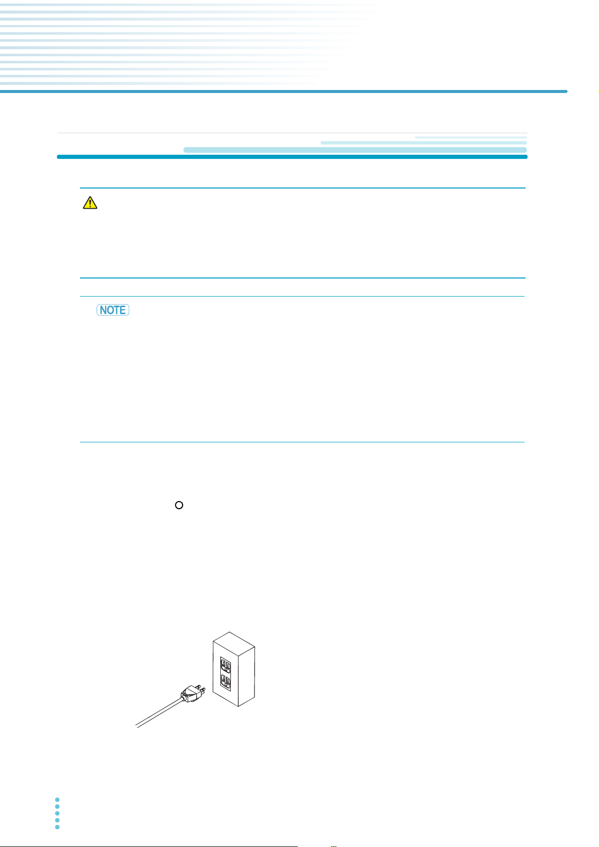
Connect the power cord to the AC INPUT inlet on the rear panel.
3
Connect the power cord plug to an outlet with a ground terminal.
4
This completes the connections.
24 User’s Manual TOS93 Series
Installation
Checking Whether the Power Is On or Off
Checking the interlock operation
When this product is turned on for the first time after purchase, it starts in PROTECTION mode in which
the interlock function (p.204) prevents tests from being executed. Check that the interlock is working properly.
Check that the power cord is connected properly.
1
Check that nothing is connected to the SIGNAL I/O connector on the rear panel.
2
Turn on ( ) the POWER switch on the front panel.
3
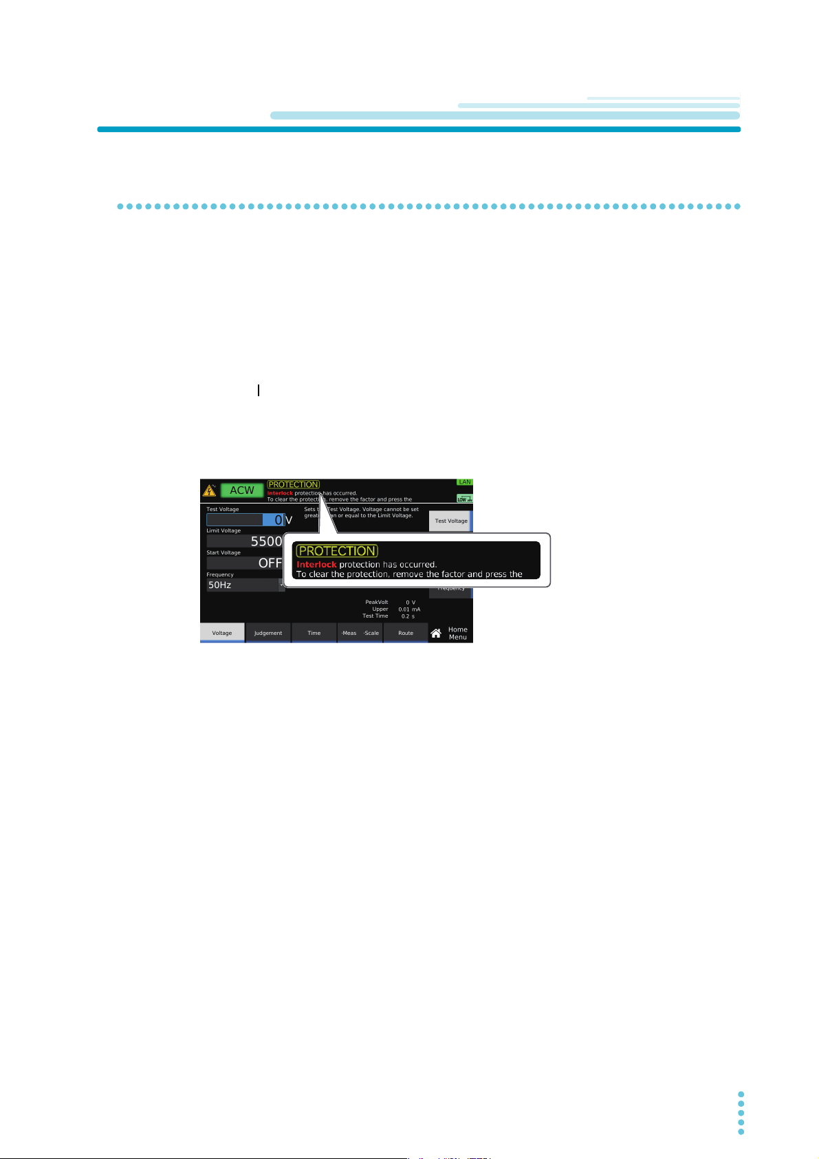
Check that PROTECTION mode is activated.
4
After the startup screen, when the product enters PROTECTION mode, the following screen
appears.
Thiscompletesthecheckingoftheinterlockoperation.
Toreleasetheinterlocktemporarily,connecttheincludedSIGNALI/OplugtotheSIGNAL
I/Oconnector,andpressSTOPonthefrontpanel.Whenyouareactuallyperformingtests,
constructasystemthatusestheinterlocktoensuresafety(p.205).
TOS93 Series User’s Manual 25
Installation | Checking Whether the Power Is On or Off
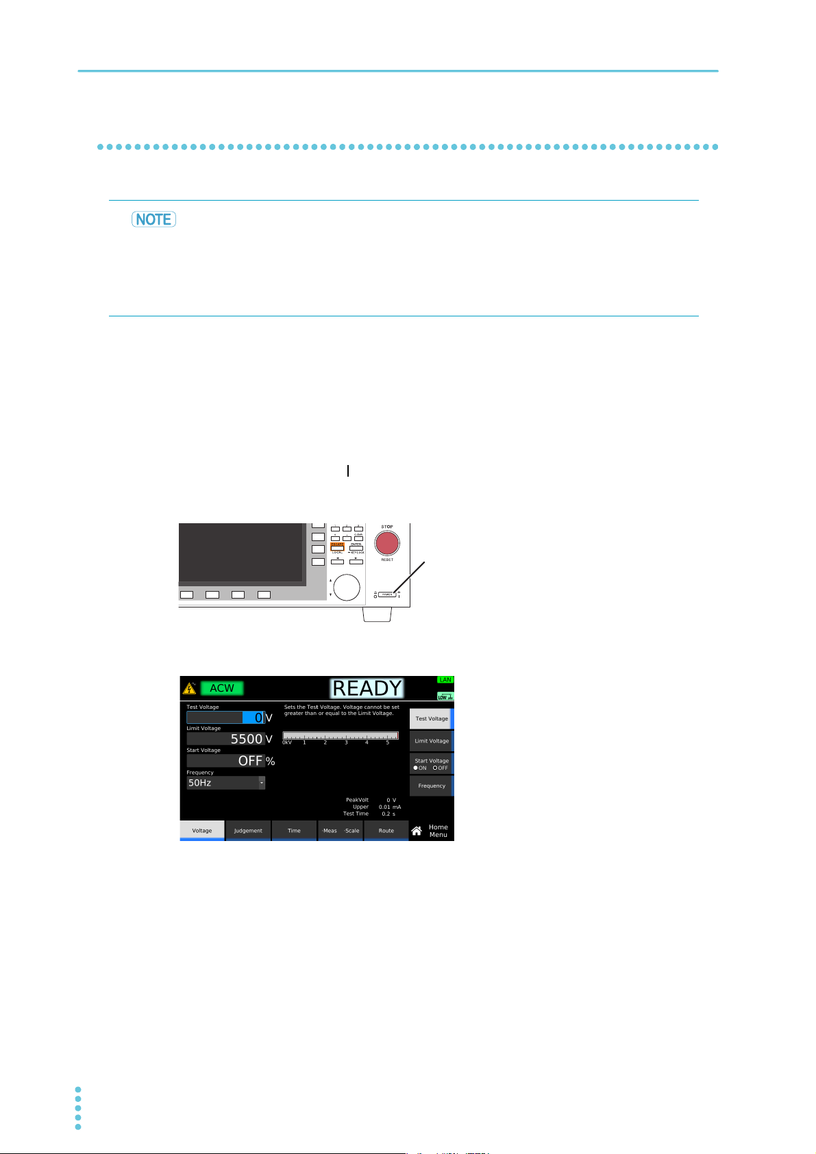
POWER switch
Turning the power on
• When the power is turned on for the first time after purchase, the interlock function sets
the product in PROTECTION mode and prevents tests from being performed. Temporarily
connect the included SIGNAL I/O plug to the SIGNAL I/O connector to release the PROTECTION mode (p.204).
• When you actually perform tests, design a system that uses the interlock for safety
(p.205).
By factory default, the panel settings immediately before the POWER switch is turned off are saved. When
you turn the power on, the product starts in the same state as it was in the last time it was turned off. (However, the output is off.)
The panel setting state at startup can be changed (p.220).
Check that the power cord is connected properly.
1
Turn the POWER switch ( ) on.
2
The DANGER LED lights, but no voltage is generated. If it does not, stop using the product, and
contact your Kikusui agent or distributor.
After the startup screen is displayed, the home screen of the test that was in use before the power
was turned off the last time appears.
The power is now on.
26 User’s Manual TOS93 Series
Turning the power off
WARNING
Turning the POWER switch off ( )
1
The power is turned off.
Risk of electric shock.
• If you want to turn the POWER switch back on, wait at least 10 seconds. It is dangerous to do otherwise, because the protective functions of the product may not
work effectively. This may cause the product to malfunction or reduce the life of the
POWER switch and internal parts such as the fuses.
• Except in an emergency, do not turn the power off while output is being generated.
Installation | Checking Whether the Power Is On or Off
TOS93 Series User’s Manual 27
Installation
9300
9303LC
WARNING
WARNING
Never touch these while
the DANGER LED is lit.
After the test leads are connected
Connection for Withstanding Voltage and Insulation Resistance Tests
Applicable models for withstanding voltage test: All models
Applicable models for insulation resistance test: , , ,
Risk of electric shock. While the DANGER LED is lit, never touch the HIGH VOLTAGE
terminal, test leads, or EUT.
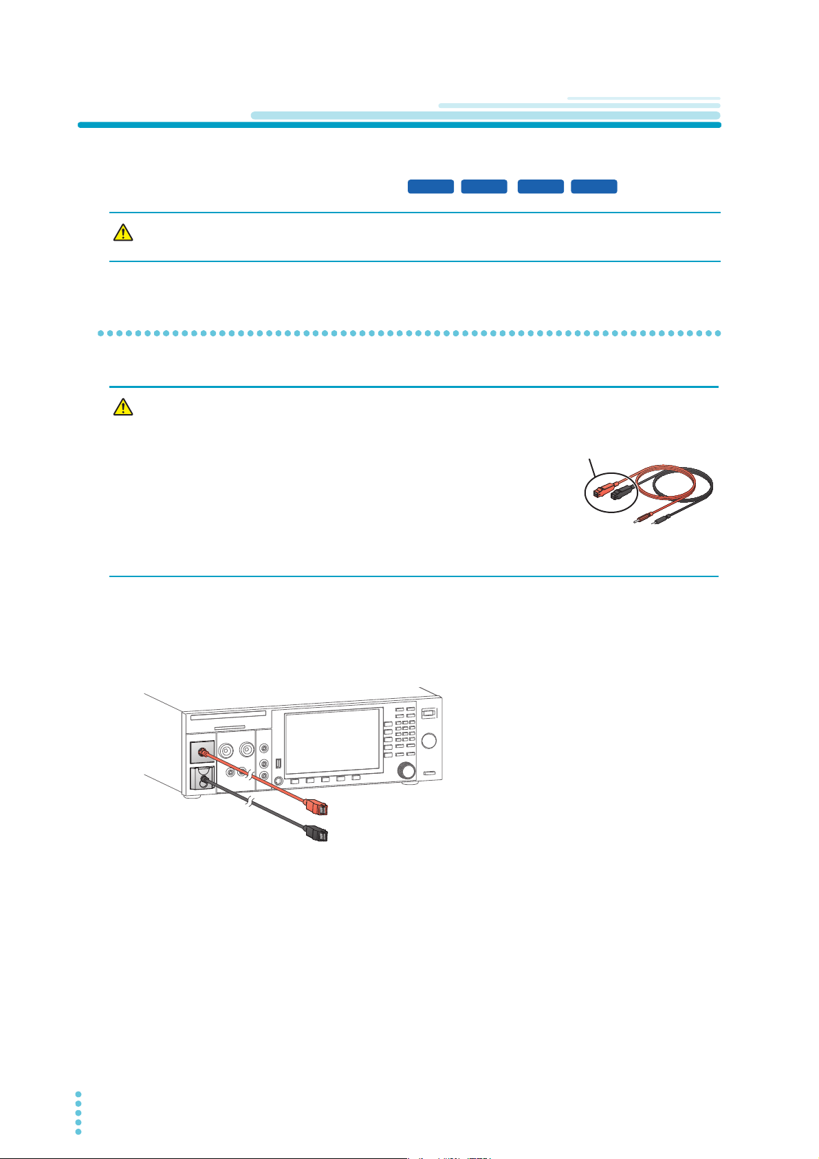
Connecting the test leads
Risk of electric shock.
• Parts of the included test leads near the alligator
clips protrude from the vinyl insulation when the
wires are connected. These parts are dangerous.
Never come close to these parts while the DANGER
LED is lit.
• If connections are incomplete, the entire EUT may be
charged to a high voltage. This is dangerous, so be
sure to connect the EUT correctly.
• Be sure to connect the low-voltage test lead (black) first.
9301
9303
Connect the supplied high voltage test lead TL31-TOS to this product.
Before starting work, check that the covering of the test leads are not torn and that the wires are not broken (p.239).
The following procedure uses the TOS9303LC as an example.
28 User’s Manual TOS93 Series
Installation | Connection for Withstanding Voltage and Insulation Resistance Tests
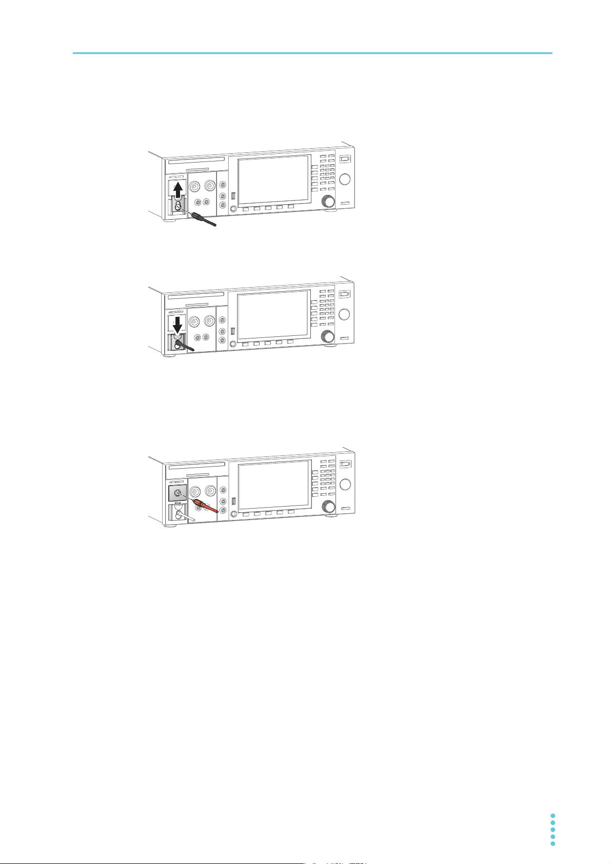
Check that the POWER switch is off and that the DANGER LED is off.
1
Raise the LOW terminal’s cable lock, and then connect the low-voltage test lead
2
(black).
Lower the cable lock.
3
Check that the connection is secure.
Connect the low-voltage test lead (black) to the EUT.
4
Connect the high-voltage test lead (red) to the EUT.
5
Connect the high-voltage test lead (red) to the HIGH VOLTAGE terminal.
6
This completes the connections.
TOS93 Series User’s Manual 29
Installation | Connection for Withstanding Voltage and Insulation Resistance Tests
To the HIGH
VOLTAGE
terminal
To the HIGH
VOLTAGE
terminal
To the LOW
terminal
To the HIGH
VOLTAGE
terminal
To the LOW
terminalTo the LOW
terminal
EUT EUTEUT
Ex: Between the power supply
(primary) and grounded
enclosure
Ex: Between the power supply
(primary) and ungrounded
enclosure
Ex: Between the insulation
connection area and
enclosure
470 ȍ, 3
470 ȍ, 3
Toroidal core
Toroidal core
HIGH VOLTAGE
LOW
TOS93TOS93
HIGH VOLTAGE
LOW
EUT
EUT
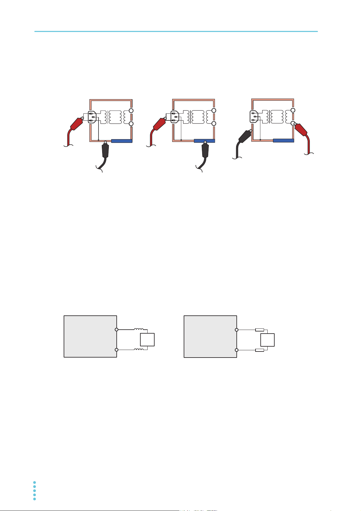
Examples of how to connect test leads to the EUT
Reducing the effect of noise
Electronic devices in the surrounding area may malfunction due to the effect of noise produced by short
circuits across outputs or a dielectric breakdown of the EUT. To reduce the effect of noise, connect a toroidal core or a resistor of approximately 470 Ω between the tips of the high- and low-voltage test leads and
the EUT. Connect the toroidal core or resistor as close to the EUT as possible.
If you are connecting a toroidal core, it is effective to wrap the test leads two to three times around a type
of core that can be snapped on and that is often used with power cords. This type of core is usually
approximately 20 mm in diameter.
If you are connecting a resistor, pay close attention to the power rating of the resistor. When the upper limit
is 10 mA or less, connect a resistor of approximately 470 Ω (3 W, 30 kV impulse withstanding voltage).
Because connecting the resistor causes the voltage to fall, the voltage that is actually applied to the EUT is
slightly lower than the voltage that is generated from the product’s output terminals (when a 10 mA current
flows, the voltage falls approximately 10 V).
These methods are extremely useful in reducing the effect of noise.
W
W
When connecting toroidal cores When connecting resistors
30 User’s Manual TOS93 Series
 Loading...